
Team-built bus body bests all
OEM meets tight development schedule on superlight multipart molded shell to offset propulsion system weight in fuel cell-powered transit bus.
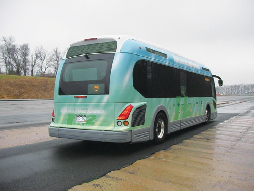
EcoRide BE35, viewed from the rear, undergoes U.S. Department of Transportation fuel economy testing on the Bus Research and Testing Facility’s test track in Altoona, Pa. It recorded fuel-economy improvement over comparable diesel-powered conventional buses of up to 400 percent, thanks in large part to its lightweight composite body. Source Proterra LLC
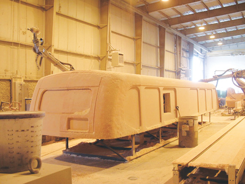
Step 2: The upper half of the bus body plug is cut to near-net shape. The lower body plug will be similarly cut, and then the upper and lower plugs will be joined. Source: DLBA Robotics
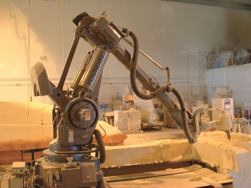
Step 1: At the DLBA Robotics facility, the robotic CNC milling system is programmed from Proterra’s 3-D solid model, in preparation for shaping the bus body plug. Source: DLBA Robotics
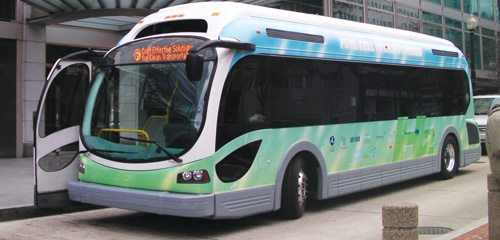
The EcoRide BE35 fuel cell-powered electric bus, designed by mass-transit OEM Proterra LLC (Golden, Colo.), benefits from and improves upon previous efforts to manufacture fuel-efficient mass transit vehicles. Source: Proterra LLC
Step 3: The upper half of the bus body plug is cut to near-net shape. The lower body plug will be similarly cut, and then the upper and lower plugs will be joined. Source: Proterra LLC
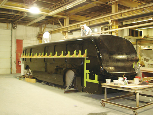
Step 5: The finished surface of the composite body upper mold is readied by technicians at C & C Fiberglass to mold a part. Source: Proterra LLC
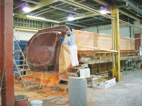
Step 4: A Pearson Composites technician checks the layup for one of the molds before it is pulled from the main bus body plug. Source: Proterra LLC
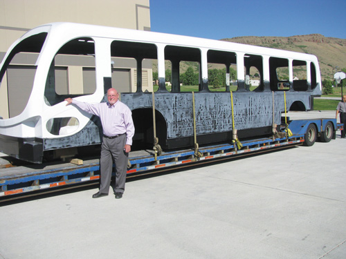
Step 6: The completed composite bus body shell prototype arrives via truck at Proterra LLC’s Golden, Colo. facility. Source: Proterra LLC


Introduced in October 2008, the EcoRide BE35 fuel cell-powered electric bus from Golden, Colo.-based Proterra LLC could prove to be one of this industry’s best fuel-efficient mass transit designs. This project was launched in May 2007 in conjunction with an award by the U.S. Federal Transit Admin., which enabled a team led by the Atlanta-based Center for Transportation and the Environment (CTE) to participate in the National Fuel Cell Bus Program (NFCBP). Transit vehicle specialist Proterra, then doing business as Mobile Energy Solutions LLC, was tasked with developing a prototype with multimillion-dollar NFCBP funding authorized in 2005 when the U.S. Congress passed the Safe, Accountable, Flexible, Efficient, Transportation Equity Act.
EcoRide represents a logical extension of knowledge the transit industry has gained through several earlier bus projects. Most important to Proterra’s design effort was previous experience with the 45-ft/13.7m EcoMark shuttle buses, in revenue service on Denver, Colo.’s 16th Street Mall since 2002. Dale Hill, Proterra’s chairman and chief technical officer and one of the principals behind the EcoMark project, notes the 36 low-floor buses “have carried in excess of 175 million passengers in their first seven years, with greatly reduced emissions due to their series hybrid-electric and compressed natural gas (CNG)-based design.” The NFCBP project updates the shuttle bus concept in a 10.6m/35-ft format. The CNG-powered engine is superseded by a hydrogen fuel system (Fab Industries, Anniston, Ala.) with filament-wound carbon fiber reinforced storage tanks, two 16-kW fuel cells (Hydrogenics, Mississauga, Ontario, Canada), and a PowerPhase 150 electric propulsion system built by UQM Technologies (Frederick, Colo.). A composite body replaced the stainless steel monocoque tube frame and high-impact plastic interior/exterior skins used in the EcoMark body. The composite body offsets the weight of, and optimizes the space required to accommodate, the hydrogen tanks and batteries. As a result, the new vehicle is able to achieve the 300-mile/482-km driving range required in normal daily transit bus operations.


Learning from others’ lessons
Proterra benchmarked previous bus bodies so lessons learned could be applied during the design phase. These included (in the order they were developed), the Metroliner in Germany; a bus once built by the now defunct Neoplan USA in Lamar, Colo.; the Southern California Rapid Transit District’s (SCRTD) Advanced Technology Transit Bus (ATTB); and two designs by North American Bus Industries (NABI, Anniston, Ala.), including the CompoBus, now in revenue service with the Los Angeles County Metropolitan Transit Authority. Although several of the designs saw limited production and little or no revenue service, the CompoBus attracted initial orders of 100 buses for L.A. Metro and 20 for Phoenix. Los Angeles recently ordered an additional 260, with options for three times that many. It should be noted that the two most significant designs deployed to date in North America are the ATTB and the CompoBus. Each features an integrated all-composite body/chassis to which the metal suspension/drivetrain systems were mounted directly. The often anecdotal operational results available for these composite buses strongly supported Proterra’s decision to move forward with an all-composite body design joined to small chassis structures manufactured from metal.Several concerns that may have hindered use of composites as the main building block of the body design in past transit body applications were no longer an issue. For example, the ATTB and CompoBus programs had put to rest concerns about side-impact crashworthiness and repairability, freeing Proterra to focus on more prosaic concerns. Chief among these were incorporating the same number of seats (37) common to longer 40-ft/12.2m buses, complying with the American Public Transportation Assn.’s (APTA, Washington, D.C.) bus design guidelines, achieving a distinctive “look,” and optimizing the bus body-in-white for cost and manufacturability within these parameters.
Proterra assigned a team of in-house personnel to the design task but involved key outside consulting firms, including Peak Composites (Arvada, Colo.) and Ultimate Composite Analysis (Piedmont, Calif.) as well as reinforcements supplier SAERTEX USA (Huntersville, N.C.) early in the process. The author’s role in the project in this context was as Proterra’s engineering director - body. This position entailed overall design responsibility for the composite body. Layout, mechanical and electrical design configuration, solid modeling and preliminary structural analysis functions were performed in-house at Proterra. SAERTEX USA’s personnel provided assistance, as did a team of composite consultants and finite element analysis (FEA) experts assembled by Proterra. Many of the team members had experience on three of the composite bus designs mentioned above, so they were ideally suited to validate and verify the in-house analysis.
FEA was a key tool in the bus design. Several load cases were investigated prior to the final decision on the basic body design. These included operational loads imposed from the road surface through the suspension (estimated using TruckSim software from Mechanical Simulation Corp., Ann Arbor, Mich.) as well as corner-jacking, towing, side impact and rollover loads. Because transit bus uniform roof-loaded rollover standards tend, historically, to “catch up” to the rollover standards for school buses, Proterra elected to design to the current Colorado school bus standard, which is considerably more demanding than that applied to transit buses. Peak Composites and Ultimate Composite Analysis separately performed extensive finite element modeling, the former using NEi Nastran (NEi Software Westminster, Calif., formerly Noran Engineering) and the latter using ANSYS (ANSYS Inc., Canonsburg, Pa.). This strategy proved advantageous because the very close agreement between the results obtained by the separate analyses increased Proterra’s confidence in the final design.
According to Peak Composites, “The design and fabrication of a fully operational composite bus is a huge project to put into action, and it is important to know as much about the end product in advance as possible. The model of the entire bus structure allowed us to predict areas of high stress under various load conditions and rapidly make changes, where needed, to mitigate areas of structural concern.” SAERTEX USA’s experts agree that “based on past design experience with other all-composite transit bus bodies and sub-components, lessons learned from these past programs were easily and quickly adopted into this battery-dominant fuel cell model and helped streamline the entire design and analysis portion of the timeline.”
Structural analysis was performed hand-in-hand with Proterra’s solid modeling of the bus body, which was accomplished in SolidWorks software, supplied by Dassault Systèmes (Suresnes, France). For example, the aesthetic and functional performance needed from the forward-opening front door meant that certain hardware needed to be mounted in or near the A-pillar. The SolidWorks model provided a check of the physical layout and clearances, and also provided the surface geometry that could readily be preprocessed and meshed for the finite element software. Results of the structural analysis, in turn, drove changes in the solid model and the corresponding full-scale shop model. This continuous interaction between designers and engineers led to an optimum body design.
Selecting and optimizing materials
Materials selection, supplier integration and structural concerns were addressed in an iterative process during design. Some key concerns are worth highlighting. First, cost requirements drove the bus body design toward a continuous E-glass fiber-reinforced composite body shell. Second, schedule needs and the desire to retain flexibility to adjust the “look” of the bus late into the design process dictated that many secondary parts, such as fuel tank covers and access doors, be hand layed, using conventional E-glass continuous strand mat and fabric reinforcements.Given the aggressive development schedule envisioned by CTE, it was essential that selected materials have a proven track record because there was little time for materials characterization. SAERTEX USA offered a complete range of suitable materials, and the company’s technical support team worked directly with Proterra’s design team during composite/component design, analysis and process-engineering phases. Particularly relevant for this project were the SAERTEX stitch-bonded Non-Crimp Fabrics (NCFs). These reinforcements are produced from layers of unidirectional fabric rather than woven fabric. Unlike weaving, stitch-bonding does not crimp the fibers. For that reason, the materials exhibit near-zero elongation in the direction of fiber orientation, making it possible to optimize the strength of the fabric in the end product and, thus, achieve improved durability (fatigue resistance) as compared to the crimped fibers in conventional wovens. A further advantage is the possibility of producing multiaxial layers with quasi-isotropic structures, such as those Proterra specified for its all-composite transit bus body. NCFs are available in E-glass, S2 Glass, aramid and/or carbon constructions, in weights ranging from 300 gsm to 3,000 gsm and in uniaxial, biaxial and triaxial fiber orientations. Many of these configurations were used in the CTE bus. Late in the design process, carbon-fiber fabrics were used locally, as the need was identified during FEA simulations, to satisfy rollover, corner jacking and other critical load cases.
Crafting the tooling
After the SolidWorks model and structural design and basic material selection were completed, the bus body “plug” was replicated by DLBA Robotics (Chesapeake, Va.), as were plugs for some of the more complicated roof fairings and internal floor sections. The bus body surface model was exported from SolidWorks to DLBA Robotics for use in their CNC dual milling robotic arms (IRB 6400 robots from ABB Ltd., Zurich, Switzerland, on a Proventia Production Technologies Oy, Oulunsalo, Finland, milling system.)The plugs were constructed on steel framework covered with a 2 lb/ft³ polyisocyanurate foam layer manufactured by ITW Insulation Systems (Houston, Texas). The foam is undercut a nominal 0.5 inch/12.7 mm and covered with fiberglass and Polyfair T27 machinable tooling resin (ATC Formulated Polymers Inc., Burlington, Ontario, Canada) and machined a final time to match the SolidWorks model.
The bus body plug was coated with a three-stage Duratec system (Hawkeye Industries, Bloomington. Calif.) and polished to obtain the final finished surface prior to mold fabrication. Duratec Base Primer was applied and sanded to a 150-grit finish by DLBA Robotics, and then the plug was shipped to Pearson Composites (Warren, R.I.) where the final two Duratec stages (EZ sanding primer and final Top Coat) were applied and the final finish was completed as illustrated in Step 3.
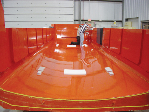
Pearson then pulled the main body molds from the plug. Tooling gel coat was applied, followed by layers of fabric until the desired laminate thickness was obtained. Parting lines for the multiple molds were determined based on manufacturing requirements, such as demolding and mold-handling ability. In some cases parting lines were located so they would be less visible (e.g., the parting line in the window belt, shown in Step 2). Body molds consisted of hand layed mold shells supported by egg-crate structures. Casters and lifting lugs were added to the tools to facilitate mobility during volume manufacture. A representative mold is shown in Step 5.
Because DLBA Robotics and other experienced composites industry players were brought in at the early stages of the project, Proterra and its tooling suppliers were typically able to manage interface tasks, such as exporting the surface geometry, with a minimum of problems. Each supplier provided important suggestions that improved the tooling and composites part fabrication. That said, even though minimal difficulties were encountered in each tooling step, the aggressive schedule for the CTE project dictated that only the most essential components of the bus body went through the initial tooling step described above. Many secondary surfaces, such as roof fairings, dash components, together with miscellaneous panels and covers, were hand tooled collaboratively by Proterra’s and personnel from C.F. Maier Composites Inc. (Golden, Colo.) and then these parts were fabricated at the C.F. Maier facility. Custom Composite Technologies (Bath, Maine), fabricated the molds for the interior floors. Separate interior floor pieces are needed to provide a controlled “A” surface that is suitable for attaching floor rubber while ensuring a satisfactory interior appearance in the passenger compartment. Ultimately, the tooling cost for the bus components ran into the hundreds of thousands of dollars.
Layup and assembly
The bus body and interior floor assemblies are molded by C & C Fiberglass Components Inc. (Bristol, R.I.), whose crew rapidly produced the first prototype composite body shells and interior walking floor segments. The bus body shell is fabricated in two pieces via vacuum-assisted resin transfer molding (VARTM). Molds are prepped and gel coated, an initial mat layer is placed to tie the resin-rich skin to the part, and then stitched-fabric reinforcements, core materials and additional fabric inner-skin reinforcements are layed up in each tool. The parts are vacuum bagged and infused, resulting in cured upper and lower shell components with a finished wall thickness of approximately 1 inch/2.5 cm. Parts are demolded and trimmed, and the upper and lower pieces of the bus are joined. The final step is the application of an epoxy-based primer and paint system, which can be supplemented with whatever “bus wrap” artwork — typically predecorated, pressure-sensitive adhesive films — the customer desires.
Unveiling and testing
Proterra’s EcoRide BE35 bus already has started making public appearances. In February it was unveiled in San Jose and made stops in Los Angeles, Sacramento and San Francisco. Concurrently, Proterra is testing EcoRide’s operating performance in field trials at various locations. Although trials are ongoing, it is already possible to say that the composite bus body has met its most important test: It came in near its target weight of 4,200 lb/1,905 kg. The completed bus, therefore, is 7,000 lb/3,175 kg lighter than its nearest competitor in the fuel-cell bus market. Achieving this weight at a reasonable cost was essential to producing a final transit product that can provide clean, energy-efficient, urban transportation using fuel cells and the latest battery technology in an advanced-series hybrid electric configuration.In March, the bus traveled to the Bus Research and Testing Facility test track in Altoona, Pa., which is used for mandatory testing of new bus designs to verify that they meet U.S. Department of Transportation regulations for fuel economy. Performed with the bus weighted to simulate the rated passenger loading and based on the “transit bus duty cycles” specified in APTA’s Standard Bus Procurement Guidelines for 30 and 40 Foot Low Floor Diesel Buses, these tests simulate real-world bus operation. Comparison with typical diesel bus fuel economies is dependent on the chosen duty cycle and is further complicated by the fact that the EcoRide BE35 can operate in both a range-extending hydrogen fuel cell mode and a short-range, all-battery electric mode. The tests confirmed the energy consumption predictions made during design, showing fuel economy improvements of as much as 400 percent compared to conventional diesel buses.


.jpg;maxWidth=300;quality=90;format=webp)


Related Content

The basics of composite drawing interpretation
Knowing the fundamentals for reading drawings — including master ply tables, ply definition diagrams and more — lays a foundation for proper composite design evaluation.
Read More
Multi-material steel/composite leaf spring targets lightweight, high-volume applications
Rassini International was challenged by Ford Motor Co. to take weight out of the F-150 pickup truck. Rassini responded with a multi-material steel/composite hybrid leaf spring system that can be manufactured at high volumes.
Read More
Protecting EV motors more efficiently
Motors for electric vehicles are expected to benefit from Trelleborg’s thermoplastic composite rotor sleeve design, which advances materials and processes to produce a lightweight, energy-efficient component.
Read More
ASCEND program update: Designing next-gen, high-rate auto and aerospace composites
GKN Aerospace, McLaren Automotive and U.K.-based partners share goals and progress aiming at high-rate, Industry 4.0-enabled, sustainable materials and processes.
Read MoreRead Next

Elevated Sky Bus railway in India features composite coach bodies
Designed to accommodate 150 commuters and travel at speeds as high as 100 kmh, Sky Bus railway transit coaches built for India's Konkan Railway (Mumbai, India) by Kineco Pvt. Ltd. (Goa, India) are expected to ease public transportation in congested metro areas. Coaches will have 4m/13.1-ft-wide sliding passenger doors
Read More
Composites end markets: Energy (2024)
Composites are used widely in oil/gas, wind and other renewable energy applications. Despite market challenges, growth potential and innovation for composites continue.
Read More