
Plant tour: Spirit AeroSystems, Belfast, Northern Ireland, U.K.
Purpose-built facility employs resin transfer infusion (RTI) and assembly technology to manufacture today’s composite A220 wings, and prepares for future new programs and production ramp-ups.
.jpg;width=70;height=70;mode=crop;format=webp)


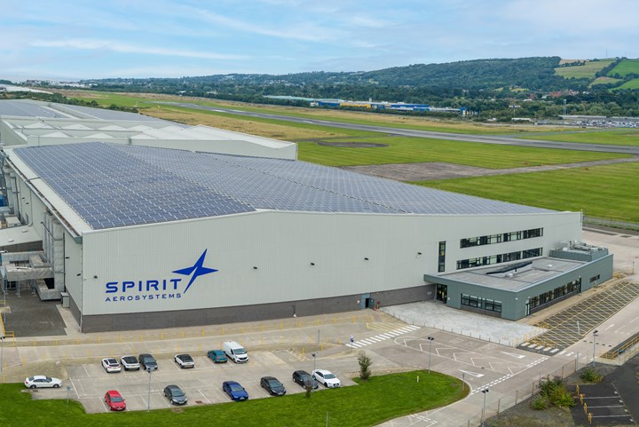
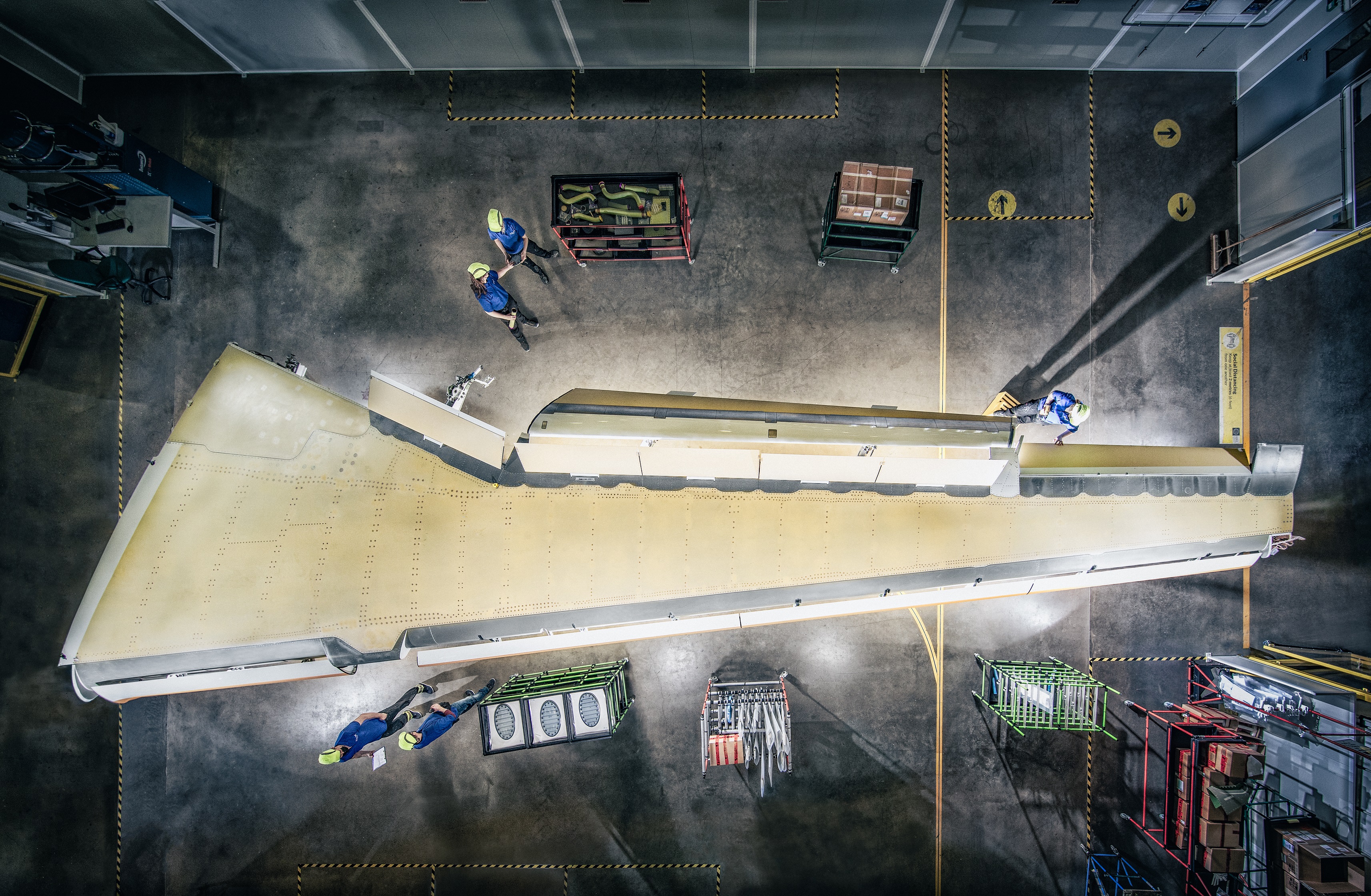
Purpose-built wing manufacturing facility. In 2020, Tier 1 aerostructures manufacturer Spirit AeroSystems acquired the Airbus A220 composite wing manufacturing facility from Bombardier in Belfast, Northern Ireland. The 600,000-square-foot facility fabricates and assembles the entire integrated wing for the A220-100 and -300. Photo credit, all images: Spirit AeroSystems
The Airbus (Toulouse, France) A220 single-aisle aircraft family, today consisting of an A220-100 variant seating 100-130 passengers and a -300 variant seating 130-160 and produced under the Airbus Canada Limited Partnership, was originally developed and launched by Bombardier (Montreal, Canada) as the CS100 and CS300, respectively, in 2008. The first C-Series aircraft entered into commercial service in 2016, and Airbus acquired a majority stake in Bombardier’s C-Series in 2018, after which it reintroduced the aircraft as the A220 family.
Most recently, Airbus has announced its intention to scale up production of the aircraft from an average of six per month in 2022 to 14 per month by the end of the decade, and has teased the eventual launch of a larger A220 variant that industry analysts have called the A220-500.


Importantly for the composites industry, Airbus reports that more than 40% of the A220’s primary structure is made from composites, including the wings, empennage and rear fuselage/pressure bulkhead, decisions that were made to enable corrosion resistance and weight savings, leading to a reported 20% increase in fuel efficiency and 50% decrease in NOX emissions. The wings specifically are made in Belfast, Northern Ireland, U.K., in a dedicated A220 wing manufacturing facility run by global Tier 1 aerostructures manufacturer Spirit AeroSystems (headquartered in Wichita, Kan., U.S.).
CW recently had the chance to tour this facility and learn more from Spirit about the development of the C-Series/A220 wing manufacturing process, current production and how Spirit is preparing for future ramp-ups and new programs.
History of Spirit AeroSystems in Belfast
Spirit claims its Belfast operations make it the largest manufacturer in Northern Ireland. Across six facilities, Spirit Belfast employs around 3,500 people and manufactures composite and aluminum structures including wings, fuselages, nacelles, horizontal stabilizers and other aerostructures for commercial, aftermarket and, increasingly, defense and space customers, including Airbus, Bombardier and Rolls-Royce (London, U.K.). The company is also involved in composites maintenance, repair and overhaul (MRO); research and development (R&D); and the collaborative research hub Northern Ireland Advanced Composites and Engineering Centre (NIACE), as well as local education and internship initiatives.
Spirit’s main factory in Belfast has been in operation since 1936, originally founded by Short Brothers PLC, obtained by Bombardier in 1989 and then ultimately acquired by Spirit in 2020. Less than a mile down the road is a purpose-built, 600,000-square-foot facility opened in 2013 by Bombardier for manufacture and assembly of the composite wings for the then-C-Series aircraft.
Ten years later, at the time of CW’s tour, the wing manufacturing facility continues to deliver the A220’s composite wings, using the patented and award-winning resin transfer infusion (RTI) process developed specifically for them.
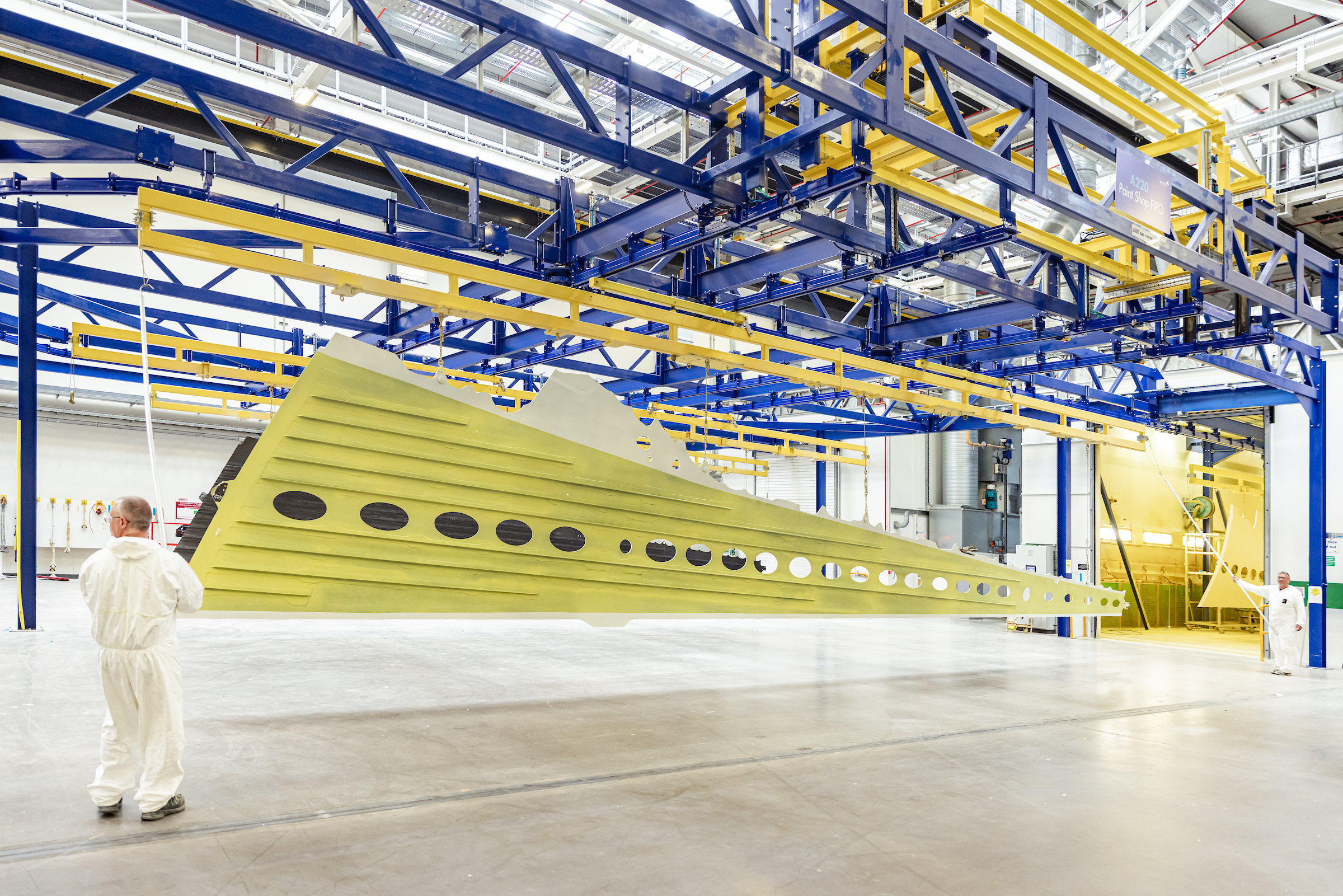
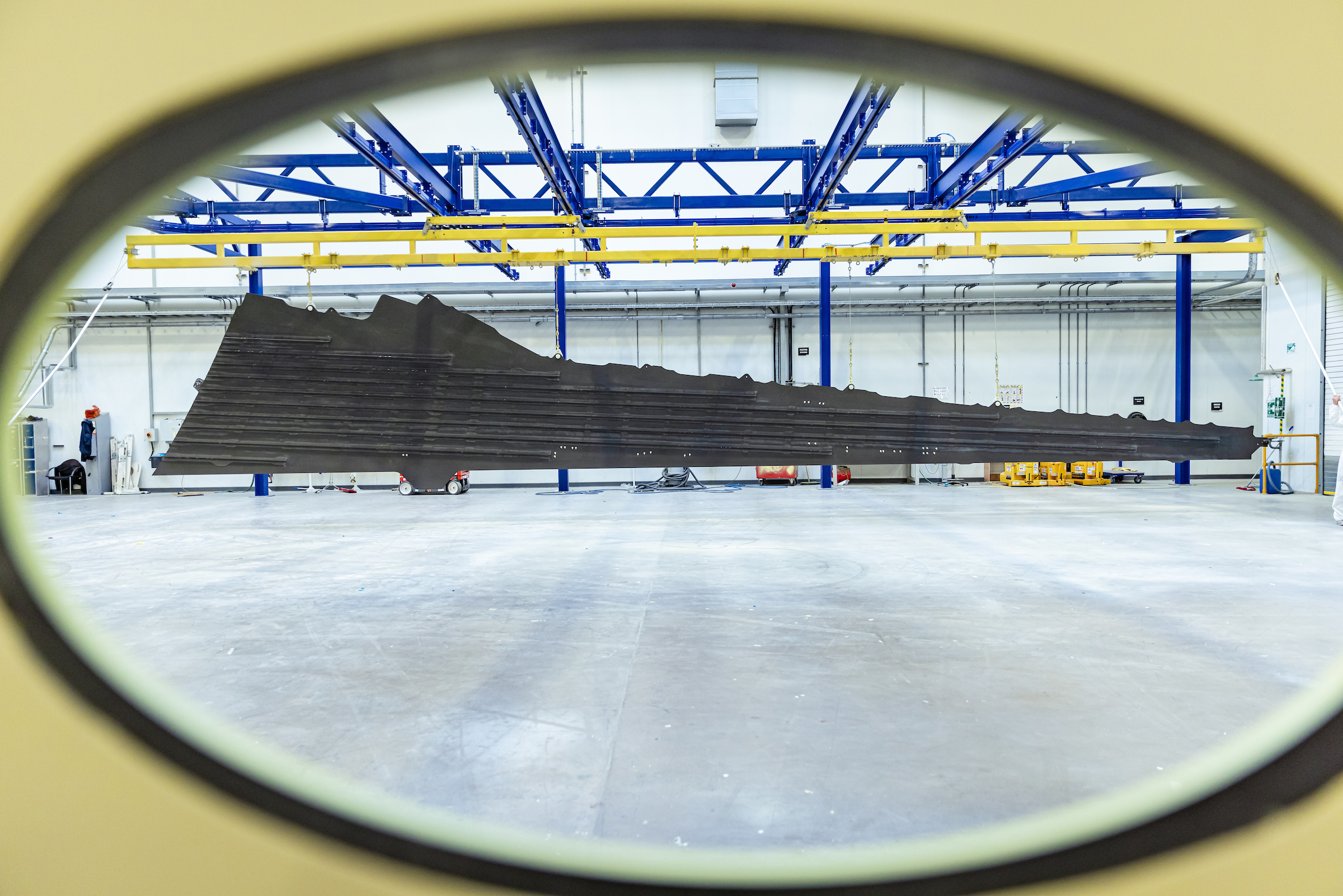
Composite A220 wings. With the exception of aluminum ribs, most of the A220 wing’s structures are made from composites in Belfast. Here, a finished wingskin with co-cured stringers emerges from the painting booth, ready to head to the assembly area of the facility.
Developing the RTI process
“The technology was developed over a 20-year period,” explains Mark Braniff, head of research and technology at Spirit AeroSystems, Belfast. The RTI process, which won the Royal Academy MacRobert Award in 2019, was developed by the Belfast site (Bombardier, at the time) as the result of an R&D strategy in the 1990s aimed at increasing automation to stay cost-competitive in aerospace manufacturing.
At this time, the few composite wings that were manufactured — mostly for small defense or regional aircraft — were made from costly and hand labor-intensive prepreg layup. Braniff, who was on the original team that developed RTI, adds that multiple technologies were innovated by the company at that time, focused on faster ways to manufacture wing structures by replacing prepreg with resin infusion of dry preforms.
He says, “Over that period, we increased our expertise in resin infusion and worked on several research programs. We developed a bespoke resin infusion technology based on current practices and our in-house derived improvements.” Patented in 1998, the process essentially combines industry-standard vacuum-assisted resin transfer molding (VARTM) with autoclave cure. “We realized right away it was going to be very hard to certify a vacuum-only resin-infused component [for commercial aircraft]. We incorporated a robust autoclave pressure cycle after the vacuum infusion phase, and that’s what really makes our system stand out from the rest of the world,” Braniff explains.
As designed, the process is largely manual with hand layup of biaxial noncrimp fabric (NCF). “Today, with advances in technology, we’re looking at more automation, and we’re actively working on that for the future,” Braniff adds.
The R&D team perfected the RTI process through manufacture of small test panels first, working up over the years to parts of increasing size and complexity, including a 12-meter wing spar for TANGO and wingskins for ALCAS, both EU-funded R&D programs. The RTI process is “highly versatile. It can be used for very large wingskins right down to quite thin-gauge composite structures such as fan cowl doors,” Braniff says. In fact, before the wing manufacturing facility was built, the first dedicated RTI facility was established in Belfast in 2007, initially focused on manufacturing STC V2500 fan cowl doors for the Airbus A320 aircraft family and the MRO market. “This was a fantastic learning opportunity and helped us de-risk the composite wing facility,” he says.
In 2008, Bombardier launched its C-series single-aisle aircraft program, and decided to target a lightweight, aerodynamic composite design for the wings to meet environmental performance, fuel efficiency and operating cost goals. Given its initial demonstrated successes with RTI, the Belfast facility was chosen to build the wings — provided it could achieve technology readiness level (TRL) 9.
Over the next two years, Bombardier put significant investment into making this happen at the Belfast site, including building a two-third size torque box with upper and lower skins, spars and stringers produced via RTI. “It was a massive transition from R&D to production, the sort of thing that doesn’t come along too often,” Braniff says. “But it was the right thing to do because it filled in all the little gaps — we developed the process all the way back to the material specs. We learned a lot from testing R&D parts, and many test results transitioned into the certification program.”
He adds, “We were on a very tight timescale to get to first flight. We had to complete the traditional pyramid of testing from coupons to sub-elements, culminating in full-scale wing testing. We achieved a large percentage of the testing in Belfast — not a lot of companies can do that anymore.” The Belfast site worked with Bombardier in Montreal and achieved certification through Transport Canada and the FAA. “It was a massive team effort,” he notes.
In 2010, commercial production began on the wings at one of Bombardier’s Belfast facilities, and Braniff and several other colleagues who had worked on the original R&D were transitioned onto the product development team for the first several years. He notes, “We were able to embed the RTI knowledge into production engineering solutions. It was a good decision, because the learning had been immense and the transfer of knowledge was very beneficial.”
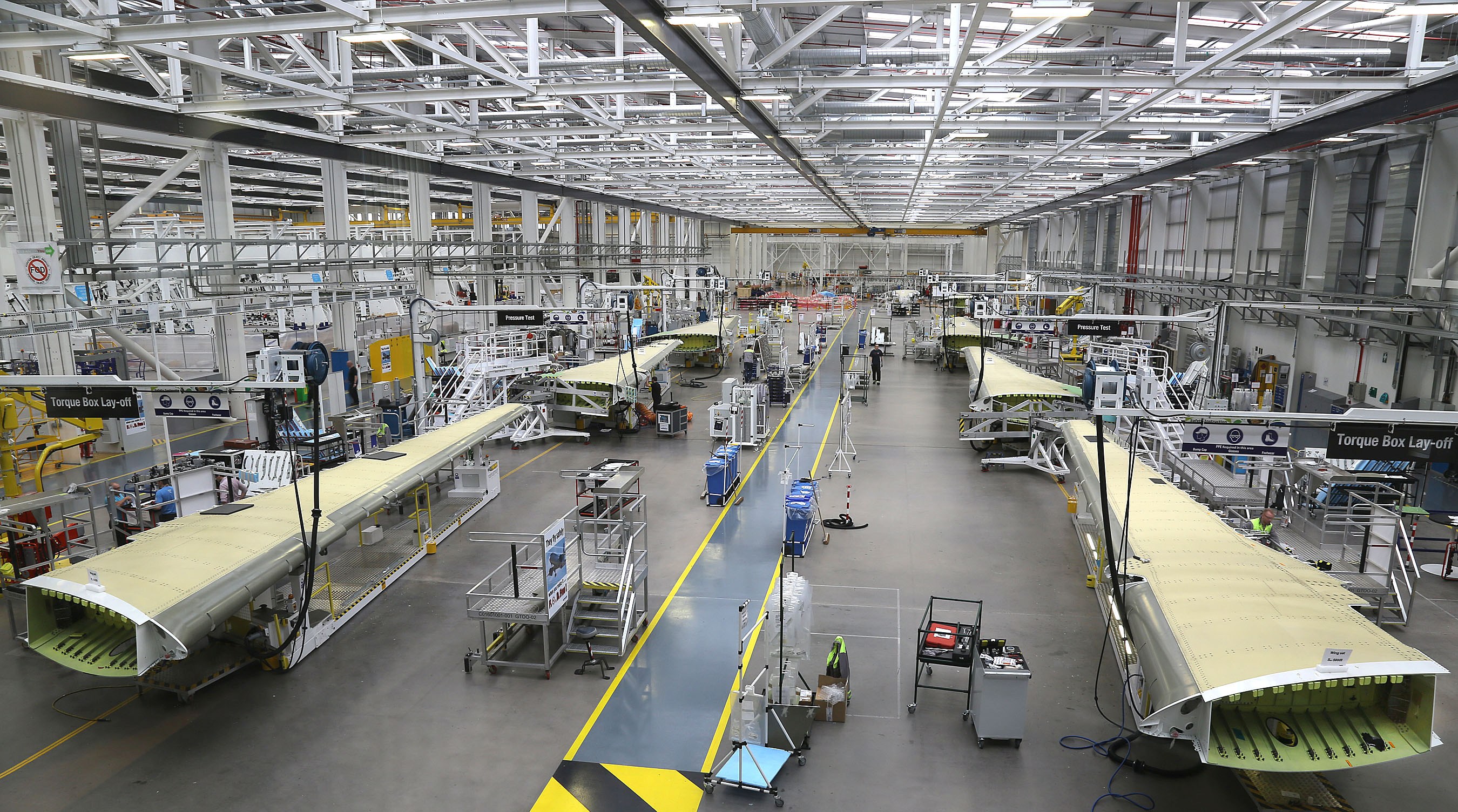
The dedicated wing manufacturing facility broke ground in 2010, and officially opened in 2013. “It’s an unusual factory,” Braniff adds, “in that it contains all the production elements from raw material receipt right through to final assembly. The basic torque box [for the A220] is all built in Belfast.”
Fabricating A220 wingskins, spars and stringers
CW’s tour begins in the 150,000-square-foot fabrication section of the facility, led by Braniff, Joanne Millar, director of Airbus operations at Spirit AeroSystems and Mark McQuillan, operations engineering manager for Airbus programs at Spirit. Here, all upper and lower wing skins, spars and stringers for A220 wings are fabricated, from layup to tool loading for infusion.
This section of the building is designated as a temperature- and humidity-controlled cleanroom, where cutting, kitting and layup occurs. Braniff notes, “Many might think a cleanroom is only needed for prepreg-based operations. However, with all of the quality controls required for aerospace manufacturing, especially co-cured stringer to skin joints, you end up almost at a cleanroom standard anyway.” Humidity control was also added to minimize moisture retention in the preforms.
Everything in the factory is integrated digitally using the company’s in-house iFactory software, McQuillan explains, which tracks all aspects of material and process conformity until the wing is ready for assembly. Employees start by scanning their identification cards at their workstations to make sure they’re approved for the project they’re working on, and the system logs who has completed which part of the process. Bar codes on tools and plies are scanned at each step of the process.
Wingskin, spar and stringer layup
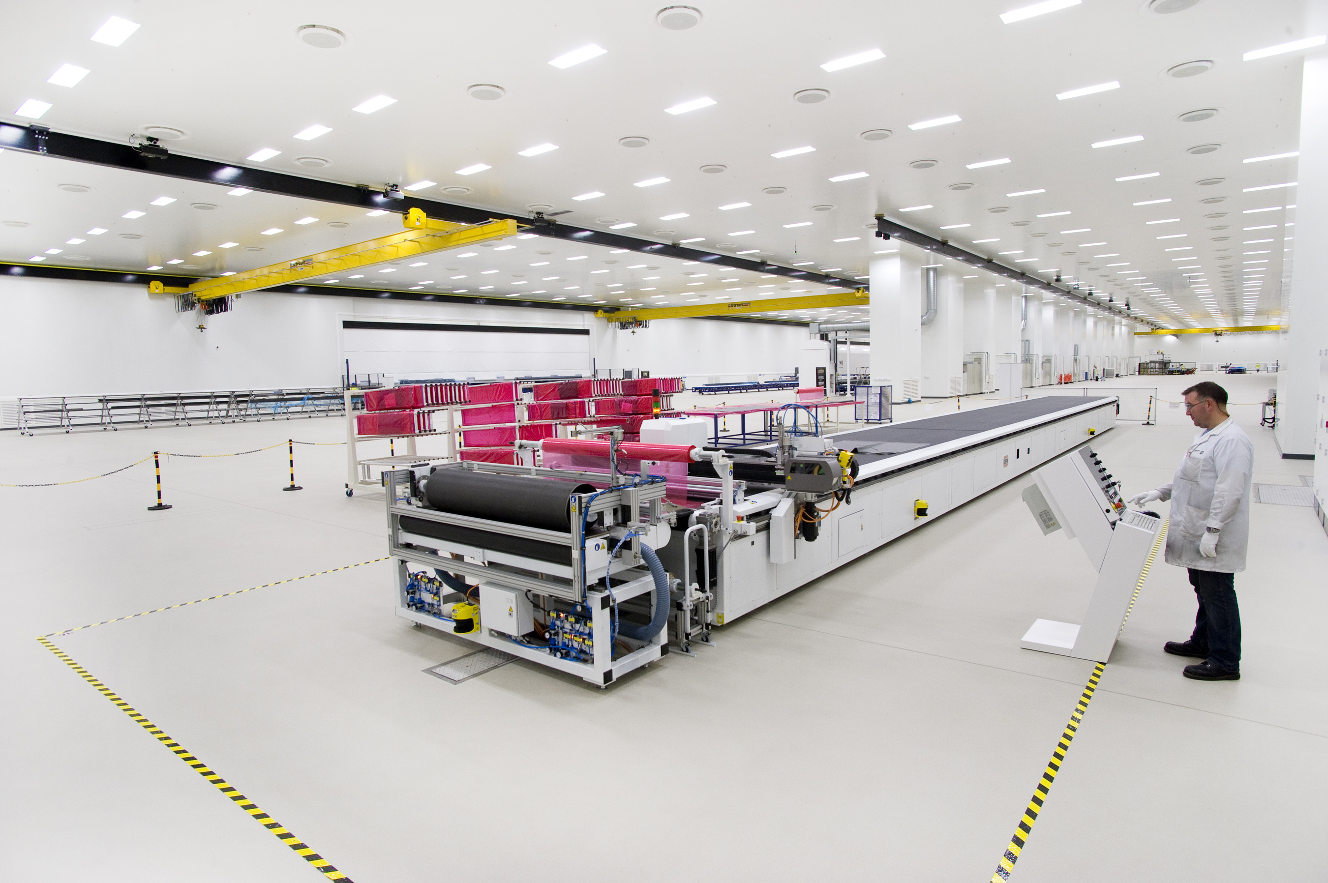
Cuts and offcuts. Pictured is Spirit AeroSystems Belfast’s 20-meter cutting bed. Not pictured is the 20-meter offcut bed. Spirit also collects manufacturing scrap which the R&D team uses for prototype tools and other efforts.
Each wing component comprises several different uni- and multi-directional carbon fiber NCFs supplied by Saertex (Saerbeck, Germany) using Teijin (Tokyo, Japan) carbon fibers. All fabrics are binder coated to facilitate preforming, and are cut using an ultrasonic cutting machine from GFM International (Retford, U.K.), which features a 20-meter cutting bed and a 20-meter offcut bed. Braniff notes that the offcut table and nearby offcut storage bins were added a few years ago, when Spirit decided to start collecting manufacturing waste and looking for potential recycling opportunities. The R&D team has begun using some of the stored offcuts to infuse and machine demonstrator tooling, with hopes of expanding into more uses in the future.
Technicians cut and kit all fabrics for multiple wings at a time. These are labeled with barcode stickers — the only paper involved in the process, McQuillan notes — and delivered to a series of wheeled storage carousels. Large plies are stored on individual “surfboards” (named for the shape of the original foam boards used for this), which consist of tube-shaped frames for wrapping the large plies. Small plies are stored in multi-drawer units.
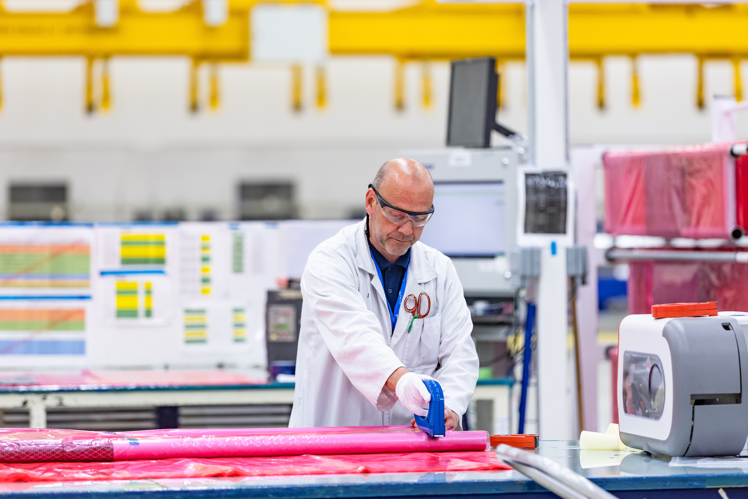
Kitting. All fabrics are meticulously kitted, barcoded and stored on “surfboard carousels” (seen in red, far back right) that are wheeled from station to station.
The surfboard carousels are then wheeled to the appropriate layup area depending on whether it is an A220-100 or A220-300 wing. Braniff explains that the outer mold line (OML) tools are manufactured from Invar for thermal compatibility with the curing wingskin. The matched inner mold line (IML) tool, known internally as a “bag,” is manufactured on site and capable of multiple cure cycles. These semi-flexible IML bags are thermally matched to the part and produced on Invar master molds for an exact fit with the wingskin preforms and stringer mandrels.
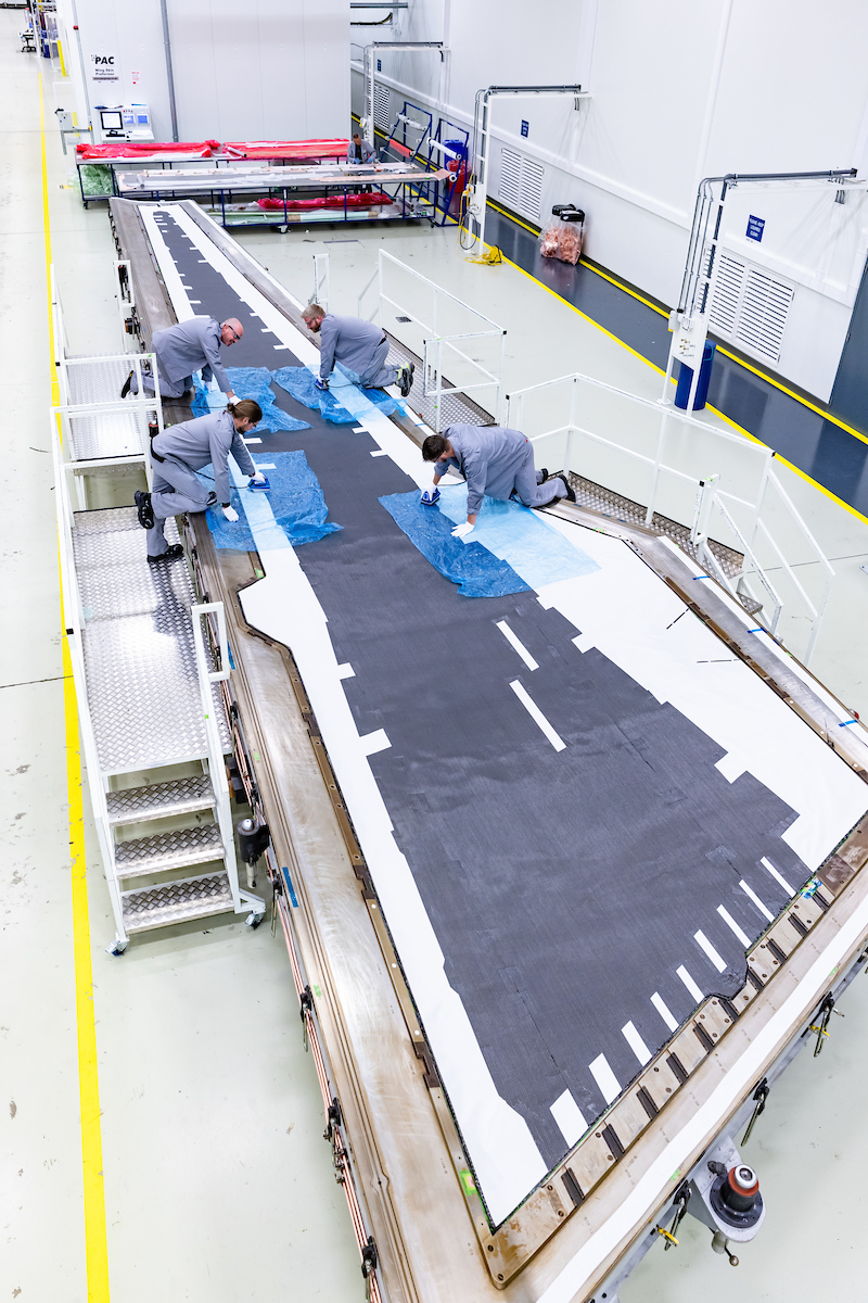
Laser-guided layup. A team of technicians lays up wingskins by hand, aided by a series of Virtek laser projection systems mounted to the ceiling throughout the facility.
A team of four technicians lays up plies by hand for each wing skin, spar and stringer, guided by a series of Virtek (Waterloo, Canada) laser projection systems installed on the factory ceiling. The layup begins with a ply of copper mesh for lightning strike protection (LSP).
Braniff says layup of the wingskins is relatively straightforward, while the stringers — each a different shape and level of curvature along the length of each wing — were more challenging, and took several years of R&D work to perfect. Saertex and resin supplier Solvay (Brussels, Belgium) provide a tailored version of the same NCFs used for the rest of the wing components, narrower rolls that can then be rolled out onto a flat stacking table and cut to length by the technician guided by the Virtek system. Each ply layer is then heat tacked to the ply beneath it, forming a “flat pack” that will then be shaped into two L-shaped preforms for the following infrared preforming process, and then connected to form the final T-shaped stringer.
Infrared preforming
Each part requires at least one infrared preforming step during the layup process, sometimes more than one depending on part complexity. Preforming is done by one of several infrared preforming systems supplied by Belfast partner PAC Group, the largest of which is the 21-meter-long × 4.5-meter-wide wingskin preformer. Each preformer includes multiple individually controlled infrared heating zones and a purpose-built cooling system. Cooling the parts down to the required temperature is the key to the process, Braniff says, to ensure that the binder holds the preform’s shape. A specially designed cooling and duct system was built for this purpose.
The stringer “flat packs” are laid up onto a series of custom carbon fiber composite holding fixtures located on a powered table. The horizontal fixtures and support mandrels are held in place by a central line of removable spacer blocks. A tailored diaphragm is lowered over the assembly and vacuum applied. In the preformer, automated infrared heat cycles form the L-shaped preforms. After cooldown, the spacers are removed and the horizontal fixtures push together to form the T-shaped stringer. A cavity void in the base of the T shape is filled with a bespoke, tackified carbon fiber noodle, which is debulked in place with a final, room temperature vacuum cycle.
Preforming. Wingskins, stringers and spars each go through one or multiple infrared preforming phases before infusion. Here, a wingskin is loaded into the machine.
The complex curvature of the spars makes them “just as challenging as the stringers,” Braniff says. The wing design and main landing gear configuration of the aircraft result in a kink in the rear spar, making it too difficult to manufacture in one piece without fiber distortion at the kink point. Therefore, the rear spars are designed in two pieces, inner and outer, that are then mechanically fastened later during final torque-box assembly.
Spar layup is challenging, with a complex flange geometry to match the associated IML surface. The spars therefore require multiple preforming cycles with specific ply layups in between to ensure the proper shape is maintained and held with no wrinkles or other distortion.
The preforming systems are set up so that as one tool or stringer layup table is in the preformer, another layup is being worked on outside of it. Thus, multiple stringers, spars and wing skins are seen in various stages of layup and preforming during our tour.
Automated stringer loading
Next in the process, before heading to the autoclave, the T-shaped stringer preforms are loaded onto the wingskin preform to form one integrated part, via a semi-automated stringer loading cell. “The cell locates the stringer preforms onto the wing skin very accurately, and is critical to achieving a successful co-cured structure,” Braniff says.
The automated system picks up the entire stringer preform tool, inverts it and lowers the preform down onto the wingskin already located on the OML cure tool. “Manually moving everything around by hand or by crane would be too difficult. The automated system ensures the preform is positioned exactly at the right place within the cure tool,” Braniff says. Then the matched IML “bag” cure tool is placed on top of the stringer and skin assembly. The integrated preform — wingskin with stringers — is ready for the autoclave.
Spar preforms are similarly lifted, rotated and placed onto female OML cure tools in a dedicated loading cell, ready for infusion.
Autoclave infusion and finishing
The tour leaves the cleanroom to enter the second half of the fabrication area, which includes the autoclaves, tool storage and maintenance, machining, nondestructive testing (NDT) and painting.
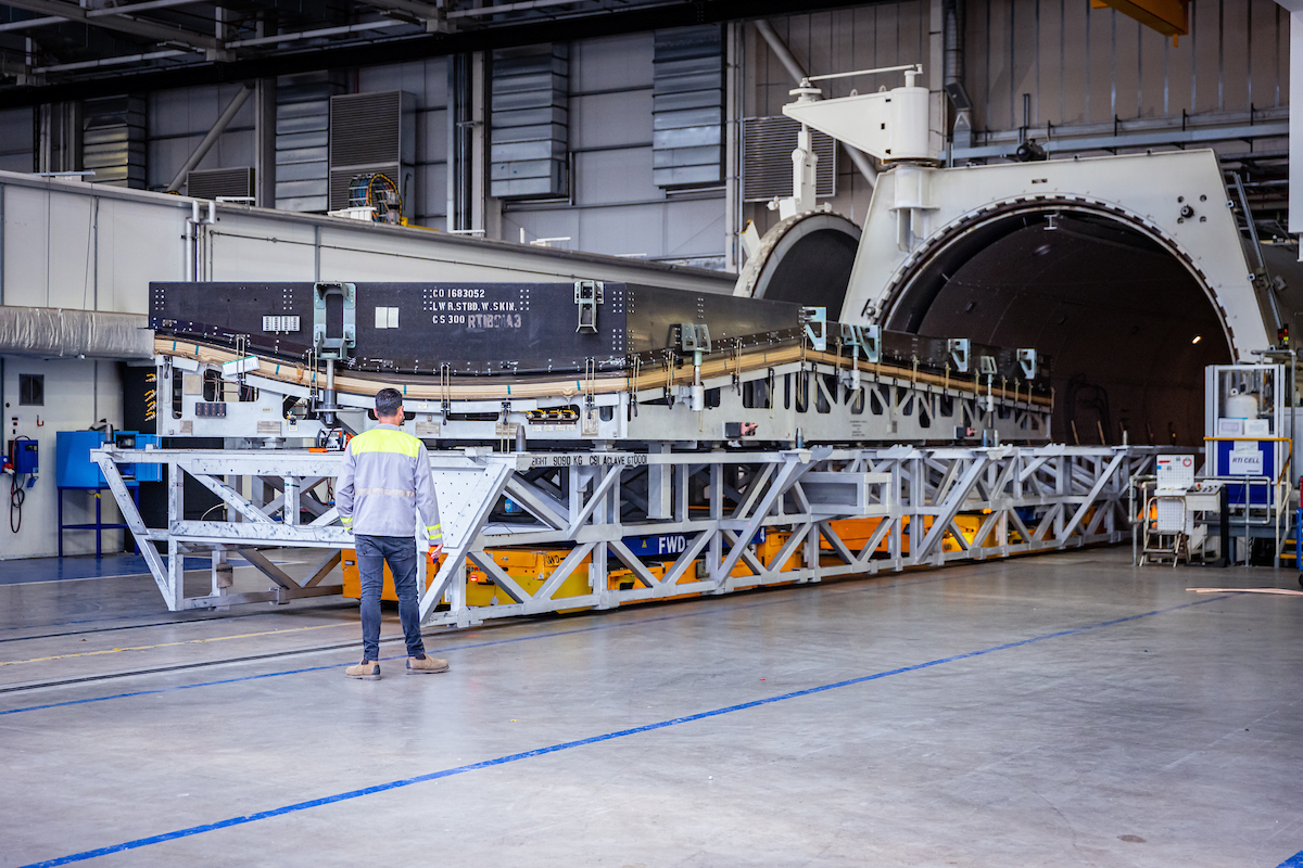
Into the autoclave. The RTI process combines resin transfer molding with an autoclave cure cycle as the most efficient, most easily certifiable way to get the needed porosity and fiber volume fraction levels. Not pictured here is the company’s most recent double-decker autoclave system, which enables the company to cure more parts at a time.
Two 70 × 18-foot Scholz (Coesfeld, Germany) autoclaves are being loaded as the tour walks by. Braniff explains that the time in the autoclave is one of the longest parts of the fabrication process, so as Spirit looks to the future and ways to meet higher manufacturing rates, this is one area of focus. In summer 2022, the company installed double-deck racks and rails within each of the autoclaves, large enough to be able to cure two full wingskins — co-cured with the stringers — at one time, or one wingskin and several spars.
This double-deck system took 18 months to design and develop. Overall, Braniff says that autoclaving more parts at one time has substantially increased output — “more than if we were to try to shorten individual cycles.” He notes that additional R&D work continues to determine if the cycle times can be shortened in other areas.
A resin injection cell next to the autoclave features Solvay Cytec 890 1K epoxy resin in 200-kilogram drums. Using a system of water-heated pots, the high-viscosity resin is heated and degassed before injection into the autoclaves via a pipe and valve system. Resin is infused into the preheated OML wingskin tools under vacuum using minimal pot pressure to maintain flow rate, Braniff explains. The autoclave is heated and pressurized to achieve the final cure parameters and to deliver parts that he claims have zero porosity and high fiber volume fractions (FVF).
Braniff emphasizes that vacuum integrity is the “secret sauce” of the entire operation, and that multiple, stringent vacuum leak tests are done before the resin is ever injected into the tool. “In this way, we can resolve any vacuum integrity issues early in the process and ultimately abort a cycle prior to injection, removing the part from the autoclave if required. It gives some flexibility for reworking the tool assemblies and avoids the loss of high-cost components.”
Ready for assembly. A cured, trimmed wingskin with co-cured stringers awaits painting and assembly.
An M&P staff member is always on site to control the infusion process, and there are several “critical process gates” or checks that have to be achieved before the infusion can proceed. “The RTI process controls the FVF very accurately. We achieve a uniform distribution of the resin and we are targeting FVFs typical of traditional unidirectional tape laid structures. Porosity is also very low,” Braniff says. Thanks to Spirit’s stringent vacuum integrity standards and control measures, he says that the attrition rate for parts is “extremely low.”
Trimming, inspection and painting
Next, the tour passes by a series of five-axis machining stations to trim the cured composite parts and to machine access cover holes into the wingskins. Holes are also drilled into the finished wingskins to aid the assembly team.
Down the line are two non-destructive testing (NDT) systems. The first is a gantry-style NDT system from General Electric (Boston, Mass., U.S.); the second is a Tecnatom (São Paulo, Brazil) phased-array inspection gantry robot cell. Both C-scan-based systems are calibrated to measure part thickness and scan for typical defects like porosity and delamination.
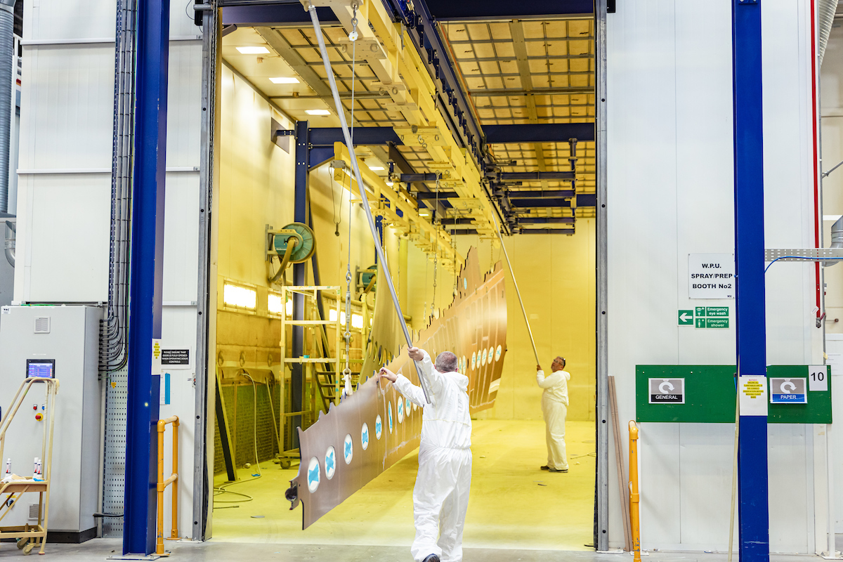
Into the paint booth. Paint is applied to protect the composite surfaces from stored fuel while the wing is in service.”
Finally, a paint booth rounds out the fabrication section of the building. A green-colored paint is used to help protect the cured composite surfaces from direct contact with fuel, inhibit moisture uptake and aid in visual inspection within the fuel tank.
Concluding the fabrication area of the tour, Braniff notes, “Having worked on the R&D program, we were able to help specify a lot of the production equipment. There’s a lot of infrared preforming technology that required a significant increase in scale. The injection system was totally bespoke to the A220 wing. The stringer manufacturing process is very special, and produces repeatable defect-free components daily. A lot of the equipment specifications came from the original R&D projects.”
Wing assembly
The overall facility is split into two parts — fabrication and assembly — with an area in between for support activities and dispatch of parts in and out of the factory. Here, various other components are also brought in from other Tier 1 partners.
The assembly area of the factory is packed with 10 assembly jigs — five for port/left-hand wings and five for starboard/right-hand wings. The jigs are positioned on edge instead of the more typical laid flat arrangement to save floor space and increase access to both sides of each wingskin at once. In this area of the facility, the entire torque box is assembled, from the wingskins, spars and stringers that are seen elsewhere in the factory to ribs, leading and trailing edges. “Ultimately, 90% of the components are composite, not including the aluminum ribs,” Millar says. Assembled torque boxes are then removed from the vertical jigs and relocated horizontally in the pulse line, where wings move sequentially down the line from station to station as systems and control surfaces are added.
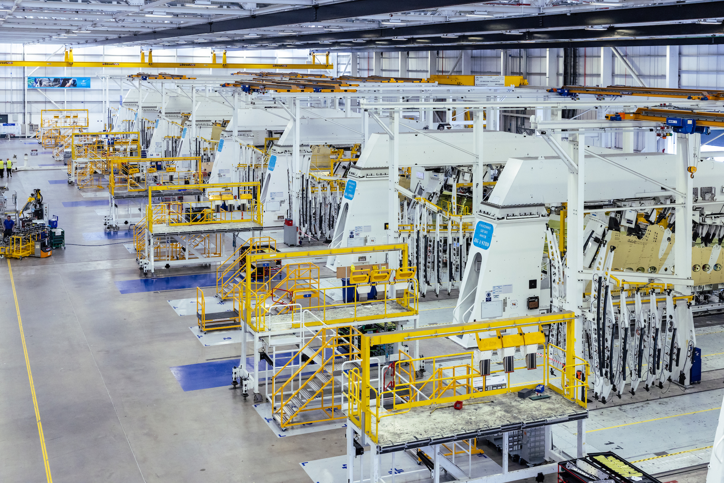
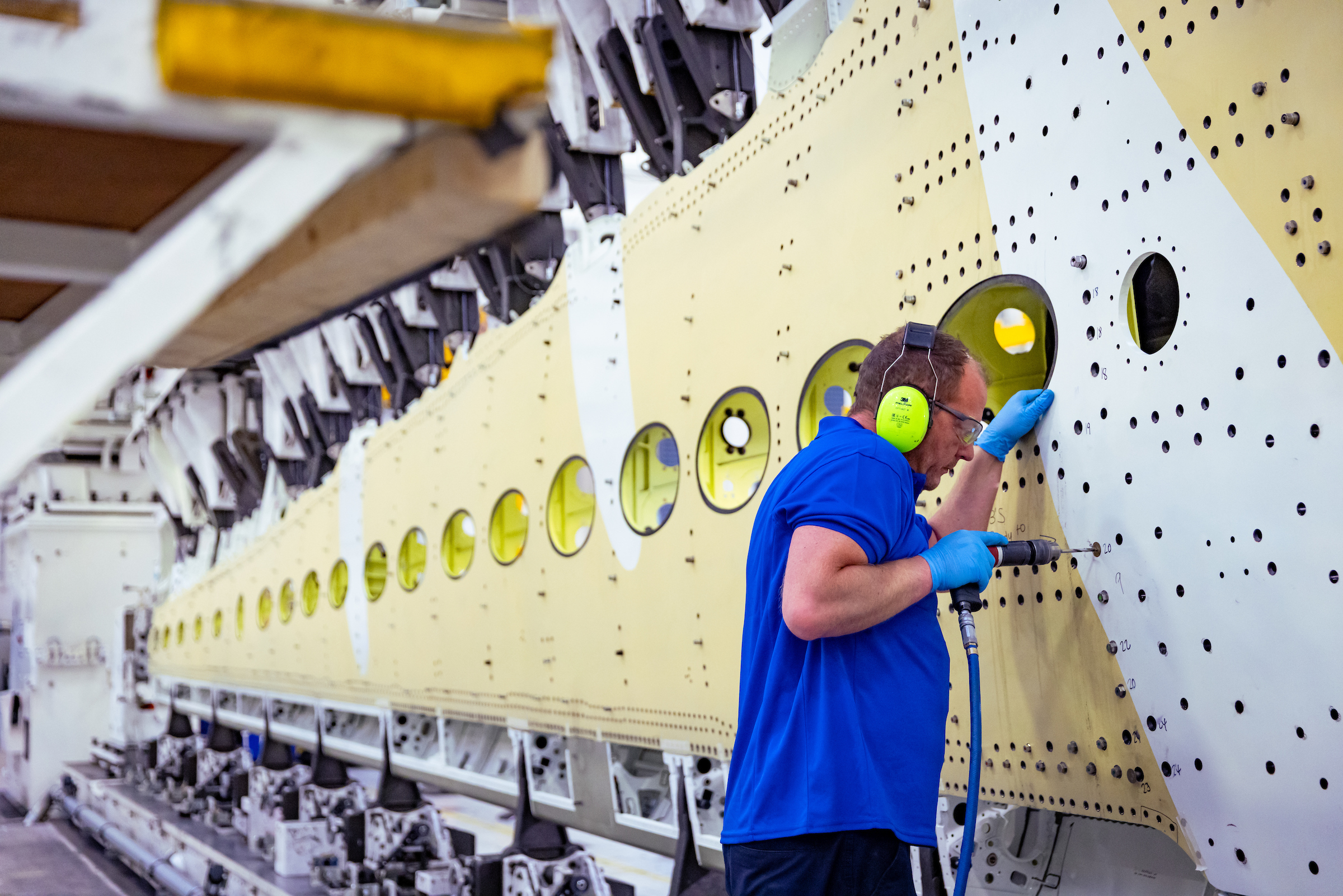
Semi-automated drilling. Drilling is one of the assembly operations done on Spirit’s line of wingskin assembly jigs (top image). Most of the 6,000 holes per wingskin are drilled by drill stations or robotic arms.
As one walks past each of the jigs, the different phases of assembly can be seen one by one. “It’s a very sequential process, much more so than a fuselage assembly,” says Millar. She explains that the assembly portion of the facility is also paperless, though running on a different software platform than the fabrication area. All specs are stored and sent to Airbus ahead of final assembly.
First, more than 6,000 holes need to be drilled into each wingskin for fasteners. “Drilling is the most critical part of the build,” Millar explains. Drilling is done via four bespoke Electroimpact (Mukilteo, Wash., U.S.) drilling stations, which drill the larger holes, and two smaller ancillary robot arms for the smaller holes. “The robotic arms work in tandem with the drilling stations, meeting up about three-fourths of the way through the wing,” she says.
Next, spars and ribs are fastened together, and the upper wingskin is attached. The lower wingskin is fastened in place last. “We worked with Airbus to create a plug-and-play situation,” Millar explains. “We finish the wing as much as possible, so that Airbus can attach the wing tips and close out the wing to the center-box joint at the final assembly line.”
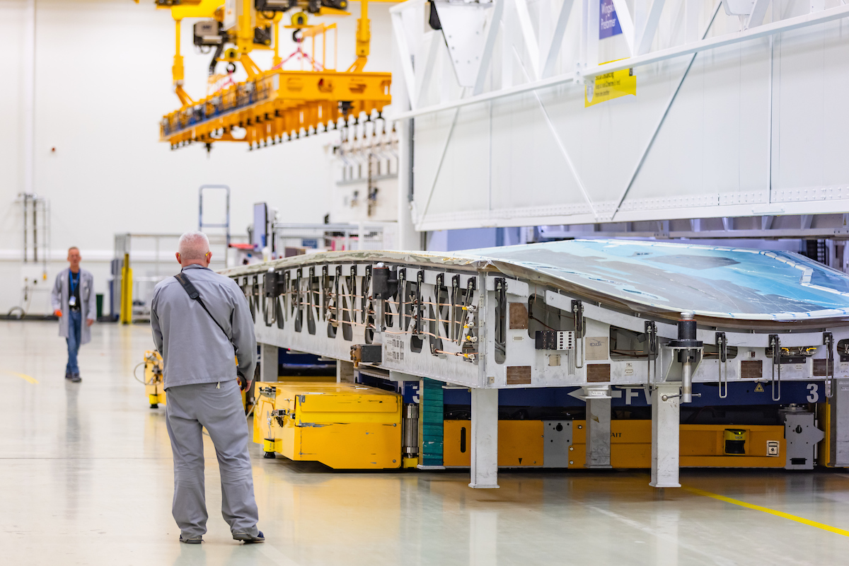
Attaching the final components. Once lifted from the vertical jigs, final components can be assembled to the wings.
A pneumatic, vacuum-assisted lifter removes each semi-assembled wing from the vertical jig and places it onto a horizontal table, where final components like leading edges and ailerons, flaps and spoilers are attached, hydraulic systems are installed and fuel leak tests are performed. Finally, the lower wingskin is sealed, and the A220 wing is ready to go.
The assembly stations form a U-turn around the assembly section of the building, leading us back to the end of the dispatch area in the middle of the factory. Here, an on-site Airbus inspector does a final series of tests before the wing is moved to a shipping container via a vacuum-assisted lifter. The flaps are removed for ease of shipping to be reassembled later. Each set of wings is shipped first to Liverpool, U.K., and then New York, N.Y., U.S., before heading to its final assembly destination at Airbus A220 assembly facilities in Mirabel, Canada or Mobile, Ala., U.S.
Increasing automation to meet higher rates
What’s next for Spirit’s Belfast wing manufacturing facility? Braniff emphasizes that faster cycle times and increased automation are the way forward, and that Spirit is working on various paths toward these ends.
For example, the company has trialed out-of-autoclave processes to replace the time-consuming autoclave process. However, “when we looked at the intricacies of heating and cooling the tools, the autoclave was the obvious choice based on demonstrated efficiencies. The autoclave is incredibly efficient at handling large thermal masses, with heating and cooling rates enhanced through pressurization,” Braniff says, as well as achieving the FVFs needed to achieve the wings’ weight goals.
Ready for flight. The manufacturing and assembly system is designed so that Airbus can “plug and play” the wings straight onto the rest of the aircraft once they arrive at the final assembly facility.
Spirit’s R&D team also designed and built a pick-and-place system to automate the NCF ply layup process, but it was expensive, “and when benchmarked against the manual process it wasn’t any faster. Once we had the teams trained up on laying down the fabric, it was the most efficient method,” Braniff adds.
Still, Spirit is working toward developing automation capabilities where they make the most sense. For example, Spirit’s Prestwick, Scotland, facility is working on capabilities for automated stringer preforming, which could eventually be installed in Belfast. Also in future the, Braniff notes that a gantry-style dry fiber placement (DFP) system could be on the table. However, to switch to DFP would mean that changes to the currently certified materials would be needed. “It’s challenging to retrofit automation into existing contracts. It’s something we’re actively pursuing though, and it may be that we develop it and use it for other platforms,” he explains.
In the future, as Airbus evolves its needs and rates, there may be more opportunities, and Spirit is exploring new manufacturing and material developments.


.jpg;maxWidth=300;quality=90;format=webp)


Related Content

The state of recycled carbon fiber
As the need for carbon fiber rises, can recycling fill the gap?
Read More
Plataine unveils AI-based autoclave scheduling optimization tool
The Autoclave Scheduler is designed to increase autoclave throughput, save operational costs and energy, and contribute to sustainable composite manufacturing.
Read More
Busch expands autoclave solutions
Busch announces its ability to address all autoclave, oven and associated composites manufacturing requirements following the acquisition of Vacuum Furnace Engineering.
Read More
Safran Nacelles Morocco installs large autoclave, doubles cleanroom per development plan to increase production rates
Extension of 6,000 square meters dedicated to Gulfstream G700/G800 production, groundwork laid to digitalize processes and reduce environmental footprint.
Read MoreRead Next

C-Series composite wing
The C-Series and Learjet 85 feature wing structures manufactured with dry fiber placement, but with cure in an autoclave. CW looks at how it's done.
Read More
Plant tour: Spirit AeroSystems, Wichita, KS
Spirit AeroSystems was an established aerospace supplier when it earned that distinction, winning the contract for the Boeing 787’s Section 41. Now its sights are set on the next generation of aircraft.
Read More
Plant tour: Spirit AeroSystems: Prestwick, Scotland, UK
Global aerostructures giant Spirit AeroSystems ventures into out-of-autoclave (OAA) composites manufacturing via vacuum infusion.
Read More