
Laminate bearing/bypass interaction test methods
Dr. Donald F. Adams (Wyoming Test Fixtures Inc., Salt Lake City, Utah) reviews laminate bearing/bypass interaction test methods.
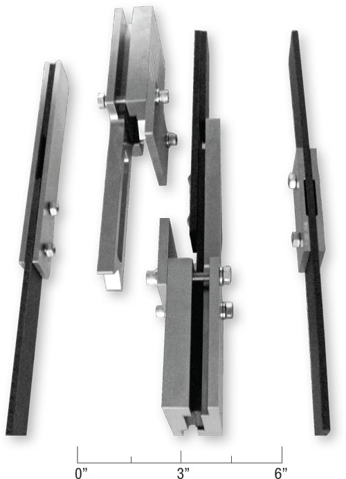
Fig. 1: Specimens and test fixtures for ASTM Standard D7248: Procedure A (left), bypass/high bearing double shear; Procedure B (center), bypass/high bearing single shear; Procedure C (right), bypass/low bearing double shear. Source Don Adams
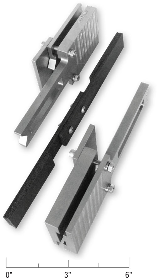
Fig. 2: ASTM Standard D7248, Procedure B specimen shown removed from support fixture.


Mechanically fastened joints are often used in structures, including composite structures, to transfer load from one portion of the structure to another. This load is primarily transferred by bearing (contact) forces that develop between the fastener and the side of the hole in the structure it occupies. These fasteners may be bolts, rivets, pins or similar devices, and the assembled structure often includes flat plates. Multiple fasteners are usually required and are arranged in some regular pattern.
If a fastener fails, the mode is typically transverse shear, and this shear strength is readily measured. On the other hand, the composite structure may fail in one or more of several other modes, including shear-out, tear-out, bearing (crushing) at the hole or net tension between holes. In these cases, the load allowable for each of these modes can be determined experimentally.


The challenge is to design the joint so that each fastener carries only an allowable portion of the total applied load so that neither it nor the hole in the composite structure fails prematurely. That is, each individual fastener transfers a portion of the total load via a bearing force exerted on the laminate around the hole, but the remaining load bypasses this fastener to act on the next fastener in line. Thus, the title of the corresponding test method is laminate bearing/bypass interaction.
The ideal test apparatus would be capable of independently applying specified amounts of bearing and bypass loads to a composite laminate specimen that incorporates a single fastener. Such active-control methods are available,1 but they tend to be equipment-intensive and, therefore, expensive to perform. Single-fastener test setups also exist for applying bearing and bypass loads in a specific ratio, with the possibility of varying this ratio by modifying the test equipment. These passive systems also tend to be somewhat cumbersome and expensive, but they are not impractical.
It is, however, possible to perform very simple tests using multiple fasteners (typically two) to achieve bearing with bypass, albeit with limited control of the ratio. This is the approach taken by ASTM in a relatively new standard, ASTM D7248,2 first published in 2007. This standard presently contains three test procedures: A, B and C. All three procedures use two fasteners, oriented in line and subjected to uniaxial loading. Procedures A and C subject the fastener to double shear. Procedure B is a single-shear test method.
Procedure A’s specimen and corresponding test fixture are shown on the left side of Fig. 1. The specimen is 200 mm/8 inches long, 30 mm/1.25 inches wide and contains two 6-mm/0.25-inch diameter holes spaced 36 mm/1.50 inches apart, with the first one 18 mm/0.75 inch from one end. The fixture consists of two flat steel plates, each identical in geometry to the specimen except for thickness. The assembly is bolted together as shown in Fig. 1, with a spacer inserted in the gripped end of the fixture plates so they remain parallel when gripped. The free end of the specimen (the lower end in Fig. 1) is gripped directly in the testing machine. The ratio of bearing force to bypassed force is somewhat fixed, because it is influenced by the specimen and fixture stiffness as well as the torque level of the fasteners and how closely they fit the holes. The fastener torque influences the amount of force resisted by friction between the specimen and the two fixture plates. A bypass failure is achieved if the specimen fails somewhere between the two fasteners. A failure at the lower fastener indicates a laminate bearing failure.
Procedure B’s specimen consists of two laminates bolted together, as shown in the center of Fig. 1. Fig. 2 shows the specimen removed from the fixture. Each laminate is 210 mm/8.25 inches long and 30 mm/1.25 inches wide, with hole patterns identical to those in the specimen for Procedure A. Spacers, each 108 mm/4.25 inches long and of the same thickness as the test laminates (usually, for convenience, of the same material), are adhesively bonded to each end of the bolted assembly so that when the specimen is gripped in the testing machine, load application is along the specimen's centerline. The specimen can be loaded in both tension and compression. Buckling is a concern when the unsupported specimen is loaded in compression, so an antibuckling fixture must be used.
The ASTM D7248 standard fixture is shown in Figs. 1 and 2. Note that this is the same fixture as used in Procedure B of ASTM D5961.3 The ends of the specimen are installed flush with the ends of the fixture (see Fig. 1). The grips of the testing machine must be wide enough (80 mm/3 inches minimum) and capable of opening sufficiently (22 mm/0.9 inch, plus the specimen thickness) to accommodate the fixture with the specimen installed. Since a compressive load will be applied, hydraulic rather than mechanical wedge grips must be used. Buckling is not a problem for tensile loading; the same fixture can be used to keep the specimen components in line to simulate an actual stabilized joint configuration. That said, use of the fixture for tensile loading is optional, but the test report must indicate whether or not it was used.
The specimen for Procedure C (Fig. 1, right side) is a 345-mm/13.5-inch long and 36-mm/1.50-inch wide laminate that contains two 6-mm/0.25-inch diameter holes spaced 50 mm/2 inches apart along the center of the laminate. Two steel doubler plates — each 90 mm/3.5 inches long; of the same width as the laminate; 5 mm/0.20 inch thick; and reduced to 3.5 mm/0.14 inch in the central region — are bolted to the laminate as shown. As for Procedures A and B, the ratio of bearing load on each fastener relative to the bypass load is governed by the stiffness of both the laminate and the doublers as well as the torque level of the bolts and how closely they fit the holes.
ASTM D7248 provides the equations for calculating, or at least estimating, the proportions of bearing and bypass loads for all three procedures.
References
1“Guidelines for Characterization of Structural Materials,” Composite Materials Handbook CMH-17/1F (formerly MIL-HDBK-17), Polymer Matrix Composites, Vol. 1, Federal Aviation Admin., Washington, D.C.
2ASTM D7248/D7248M-08, “Standard Test Method for Bearing/Bypass Interaction Response of Polymer Matrix Composite Laminates Using 2-Fastener Specimens,” ASTM International (W. Conshohocken, Pa.), 2008.
3ASTM D5961/D5961-10, “Standard Test Method for Bearing Response of Polymer Matrix Composite Laminates,” ASTM International (W. Conshohocken, Pa.), 2008.


.jpg;maxWidth=300;quality=90;format=webp)


Related Content

CFRTP enables better, greener smartphones
Carbon Mobile’s “monocoque” design eliminates separate case, cover and frame, better protects electronics and simplifies disassembly.
Read More
Materials & Processes: Tooling for composites
Composite parts are formed in molds, also known as tools. Tools can be made from virtually any material. The material type, shape and complexity depend upon the part and length of production run. Here's a short summary of the issues involved in electing and making tools.
Read More
Nine factors to consider when designing composites cure tooling
Gary Bond discusses the common pitfalls and compromises when designing good cure tooling and their holistic significance for a robust composite production process.
Read More
Thermoplastic composites welding: Process control, certification, crack arresters and surface prep
More widespread use of welded composite structures within a decade? Yes, but further developments are needed.
Read MoreRead Next

CW’s 2024 Top Shops survey offers new approach to benchmarking
Respondents that complete the survey by April 30, 2024, have the chance to be recognized as an honoree.
Read More
Composites end markets: Energy (2024)
Composites are used widely in oil/gas, wind and other renewable energy applications. Despite market challenges, growth potential and innovation for composites continue.
Read More
From the CW Archives: The tale of the thermoplastic cryotank
In 2006, guest columnist Bob Hartunian related the story of his efforts two decades prior, while at McDonnell Douglas, to develop a thermoplastic composite crytank for hydrogen storage. He learned a lot of lessons.
Read More