Avoiding the pitfalls of vacuum infusion processing
Understand the fundamentals of vacuum infusion processing (VIP), including pressure, permeability and race tracking, to prevent issues and produce consistent results.
Share
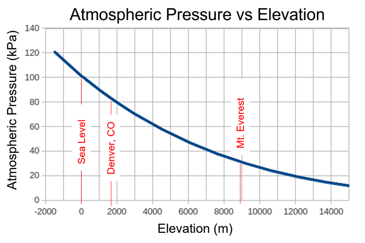
Fig 1. Atmospheric pressure vs. elevation. The relationship between elevation and atmospheric (atm) pressure is non-linear as represented by this graph. Photo Credit: Abaris, as adapted from The Engineering Toolbox.
Many issues arise during the vacuum infusion process (VIP) that can be prevented with a little foreknowledge of certain variables and attention to detail, which can help produce consistent results. This month we explore ways to reduce or prevent problems ahead of VIP, which uses vacuum-only (atmospheric pressure) to drive resin through a laminate. Here we focus on pressure, permeability, race-tracking and related issues.
Importance of vacuum-atmospheric pressure
First, a review of the vacuum-atmospheric pressure relationship. Theoretically, one atmosphere (atm) at mean sea level is equal to 14.7 psi (1,013 mbar) or 29.92 inHg (760 mmHg) vacuum, at 59°F (15˚C). As elevation increases, pressure decreases at a rate of around -0.53 psi (-36.54 mbar) or -1.08 inHg (-27.432 mmHg) per 1,000 feet (304.8 meters) of altitude (Fig. 1). To simplify all of this, just remember that for each 1 inHg loss of vacuum, you will lose approximately 0.5 psi of pressure on your bag. For example, when pulling 29.9 inHg (gauge) on a leak-free vacuum bag, the atm pressure is ~14.7 psi or 2,117 pounds per square foot (lbs ft2) of area. When vacuum is reduced to 24 inHg, the atm pressure is ~12 psi or 1728 lbs ft2 of area. This example shows a significant loss in compaction pressure on the fiber/fabric stack (preform) that can affect laminate quality, reducing the flow rate and possibly the maximum distance of resin flow within a preform. (See Evaluation of permeability below.)
VIP works by creating a pressure differential within the preform between the non-porous membrane (vacuum bag) and the mold surface when full vacuum is applied to the cavity. This produces pressure, which moves resin into the low-pressure areas that exist within the preform. Therefore, the importance of having a tightly sealed and leak-free mold and bag cannot be underestimated. Without question, minor vacuum leaks will greatly affect the VIP process. For this reason, it is important to check the following prior to committing to an actual part:
- Test for leaks in the mold
- Ensure that the bag and seals are not leaking
- Check external plumbing and connections for leaks.
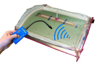
Fig 2: Leak detector. A leak detector can be helpful in finding leaks in the bag or seal. It may be less useful for finding diffuse leaks in a mold. Photo Credit: Abaris
This can all be performed in one test. A breather material is placed within the part area on the mold, and vacuum plumbing (spiral tubing) is installed around the periphery, making contact with the breather material. Then, two tees (or vacuum ports) are installed on opposing sides of the bag; one will be connected to the external vacuum line and the other to a vacuum gauge. The bag is then installed and sealed to the mold surface, the penetration for the vacuum and gauge tees are sealed to the bag, external plumbing is attached to the vacuum tee and full vacuum is drawn for a period of 5-10 minutes after the bag is deemed “tight.”
At this point, the vacuum source tube is clamped, or a valve placed in line is shut, and the vacuum gauge is monitored for movement for a period of 10 minutes. A good mold/bag should have <1 inHg loss over this time. If the loss exceeds this standard, vacuum is reapplied and the bag, seals and fittings are checked again using an ultrasonic leak detector (Fig. 2) until they are found and properly fixed. If the mold is leaking internally and the leak check standard cannot be met, it may require rework or replacement to mitigate the problem. It should be noted that a leak can allow outside air to ingress into the infused part, and depending upon where it is located, it can lead to surface porosity and voids in the resulting laminate, as well as a significant loss in pressure needed to obtain the calculated fiber volume fraction (FVF).
Another useful tool for detecting leaks is an inline flow meter (Fig. 3). This device is installed between the vacuum source and the tee (or port) to the bag. It measures flow with a small ball that moves up when flow is detected and down to a static state when the bag is fully sealed.
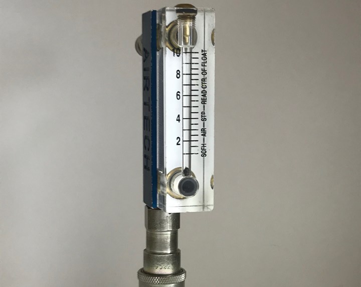
Fig 3: Flow meter. The inline flow meter is used to ensure a leak-free setup. It measures flow with a small ball that moves up when flow is detected and down to a static state when the bag is fully sealed. Photo Credit: Abaris.
Evaluation of permeability
To be successful with infusion processing, one must have a fundamental understanding of the concepts of liquid flow through a porous (permeable) medium as is defined by Darcy’s Law. To simplify this law as it applies to resin infusion, we need only understand that the rate at which a resin flows through a specified preform is proportional to the permeability of that stack and inversely proportional to the dynamic viscosity of the resin. In other words, the lower the resin viscosity, the faster and farther the resin can flow through a known preform with consistent atmospheric pressure (vacuum) to drive it. Heating the mold or the resin reduces the viscosity but may accelerate the cure time. If heat is used, all testing should be done at the prescribed temperature of the intended process.
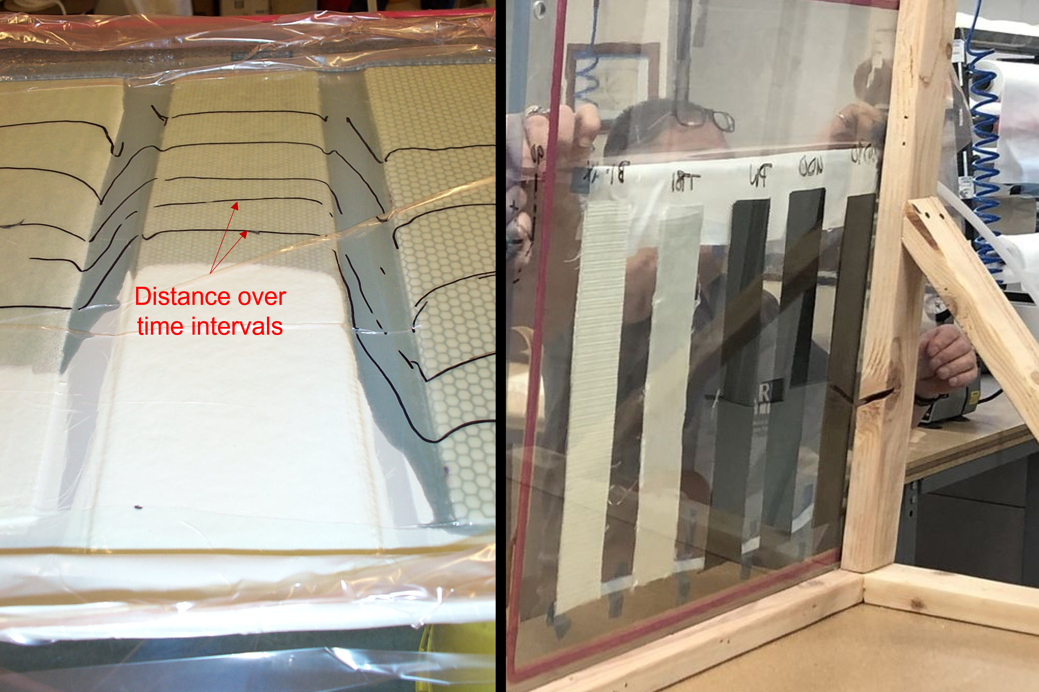
Fig. 4. Horizontal and vertical flow tests. Marks on the horizontal flow test (left), show the incremental distance over time relationship. A vertical setup (right) uses a glass pane for visibility. Photo Credit: Abaris, CompositesWorld.
Simple tests are performed to establish permeability, or how fast and far a specific resin will move through a given preform. It is recommended that this be done both horizontally and vertically (yes, gravity is a factor) with the designated preform and the selected resin system to establish the maximum flow distance, over time, at an isothermal temperature (Fig. 4). This study marks the maximum spacing of the resin inlets/feed lines for both horizontal and vertical surfaces. The spacing should always be conservative, i.e., inside the maximum distance line by a few inches. Of course, all of this can be computer-modeled and simulated, but we will stick to the basics for the purpose of this discussion.
Race-tracking: Equilibrium pressure
Anyone who has performed resin infusion processing is familiar with “race-tracking.” This occurs when resin runs around the edges of core materials, inserts or other details within the layup or the mold, wherever a gap exists between layers in the preform or to the mold surface. This occurs when the fiber preform (or bag) is bridged and an open space remains to create a low-pressure area — a “path of least resistance” for resin to flow ahead of the normal flow front.
Fig 5: Race-tracking: Equilibrium pressure. These photos illustrate how resin race-tracks around a detail in the layup and comes to an equilibrium pressure, inhibiting further wetting in the center of the detail. (A.) shows the flow front progression, first around the doubler ply installed under the detail. (B.) shows resin flow as it continues around the doubler and detail until it hits the break zone. (C.) shows the resin continuing to wet around the edges of the detail until it reaches equilibrium pressure and cannot advance any further. The yellow arrow shows where vacuum egress is necessary across the detail area to wet out the dry spot. Photo Credit: Abaris
Fig. 5 depicts a situation where race-tracking around an oval detail has caused the center area of the detail to come to an equilibrium pressure without achieving complete wetout. The simple fix at this point would be to use a syringe attached to a vacuum source to penetrate the bag in the center of the oval area, creating a pressure differential, thus allowing it to wet out. Beforehand, it would have been wise to install a pleat with a vacuum path that runs across the center area of the detail to prevent this from happening.
VIP takeaways
We have examined just a few areas of VIP requiring a fundamental understanding by the operator, but there are many more areas to be explored. For now, these are the takeaways:
- Using full vacuum/pressure leads to consistency in laminate quality. The importance of a leak-free tool, vacuum bag and other hardware cannot be understated and should never be overlooked in the name of saving time.
- Permeability of the preform must be understood before committing to a large-scale project. Maintaining a constant resin/mold temperature is paramount to repeatable permeability of the preform. Resin inlet spacing can be determined by running permeability trials ahead of time.
- Race-tracking can be a valuable method for rapid resin distribution; however, accommodations must be made ahead of time to prevent a pressure equilibrium where the preform is unable to sufficiently wet out.
I always say that knowledge is the great result of failure and is the grand patriarch of experience. Those with experience have likely encountered these issues while those that are new to VIP may still be learning. It is our hope that this writing will provide the reader, regardless of their experience, with a bit of knowledge that can be immediately applied and help to foster success.


Related Content

Composite buildings go monocoque
Superior protection from the elements plus fast, affordable installation and maintenance have quickly made Orenco Composites’ DuraFiber buildings an attractive choice for water and wastewater, communications, transportation and power industry outbuildings.
Read More
Engine vane demonstrates potential for gapped, unidirectional dry fiber for infusion
GKN Aerospace and its partners developed an aircraft demonstrator component made with TeXtreme’s latest Gapped UD material, proving out a dry, infusible tape meant to compare in performance to UD prepreg.
Read More
Understanding vacuum bagging layers in production, repair
Recognizing the functions of each layer in a vacuum bag schedule can help users discover what vacuum bag schedules work best for their application.
Read More
Refurbishing bridges at half the time, cost versus replacement
Instead of demolishing and rebuilding bridges, SUREbridge doubles the strength and durability of existing structures with an FRP deck for a smart, sustainable solution.
Read MoreRead Next

Porosity, voids and bridging in prepreg autoclave and vacuum bag-only laminates
Consideration of materials, methods and systems explores ways to reduce potential surface porosity, voids, resin-rich areas, bridging and other flaws in composite laminates.
Read More
From the CW Archives: The tale of the thermoplastic cryotank
In 2006, guest columnist Bob Hartunian related the story of his efforts two decades prior, while at McDonnell Douglas, to develop a thermoplastic composite crytank for hydrogen storage. He learned a lot of lessons.
Read More
Composites end markets: Energy (2024)
Composites are used widely in oil/gas, wind and other renewable energy applications. Despite market challenges, growth potential and innovation for composites continue.
Read More