
SkyPath: Scenic bikeway/walkway a winner with composites
E-glass/carbon/epoxy provides the means for this long-sought addition to a 1.1-km harbor bridge in New Zealand’s capital city.

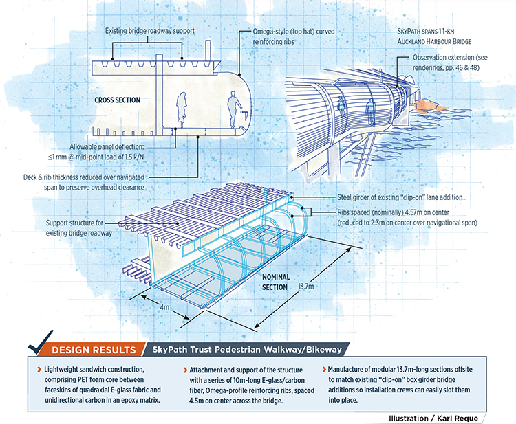
SkyPath Trust Pedestrian Walkway/Bikeway Illustration: Karl Reque
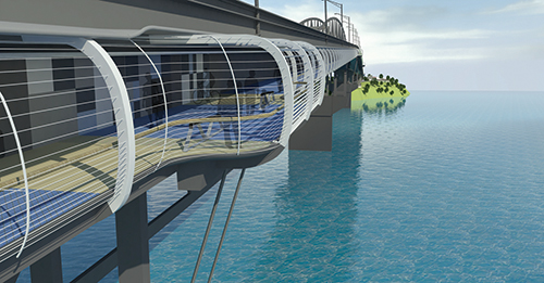
The Architect’s Only Answer: SkyPath’s lightweight composite design not only helped engineers meet strict load restrictions on the bridge — a consequence of a previous retrofit and remediation that added car/truck lanes and much additional weight — but it also provided architects with greater freedom to incorporate design features both aesthetic and user-friendly. Source: Reset Urban Design
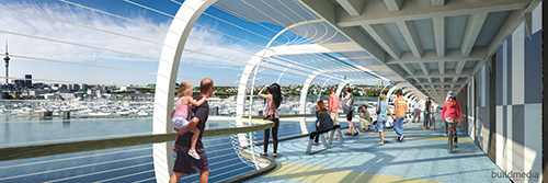
Walkway/Bikepath with a View: The SkyPath interior features a composite deck wide enough to permit separate bike and foot traffic lanes. The deck, here, is wider still to undergird one of five observation extensions on SkyPath which will enable path users to step out of traffic to enjoy a panoramic view. Source: Reset Urban Design


Design Results:


- Lightweight sandwich construction, comprising PET foam core between faceskins of quadraxial E-glass fabric and unidirectional carbon in an epoxy matrix.
- Attachment and support of the structure with a series of 10m-long E-glass/carbon fiber, Omega-profile reinforcing ribs, spaced 4.5m on center across the bridge.
- Manufacture of modular 13.7m-long sections offsite to match existing “clip-on” box girder bridge additions so installation crews can easily slot them into place.
The 1,020m Auckland Harbour Bridge is one of only two bridges that span Waitemata Harbour, connecting the city of Auckland, New Zealand, to populous suburban areas on the waterway’s North Shore. Since its inception in 1946, the bridge has been a work in progress. Although a Royal Commission originally recommended a five- or six-lane bridge with footpaths on either side, the New Zealand government opted for the more affordable four-lane, no-footpath design that opened to traffic in 1959. On the occasion of the bridge project’s 50th anniversary in 1996, a New Zealand Herald editorial called that decision “a ringing testament to ... the peril of short-term thinking and penny-pinching.”
In 1969, remedial action took the form of “clip-on” two-lane box girder sections attached to each side of the bridge, doubling the number of lanes. Attached only at the main piers, the section load is transferred via pier brackets — the box girders are independent of the bridge’s structural truss and are connected to each other by transverse steel cross-braces. Although this solution was projected to have a 50-year lifespan, unanticipated wear and fatigue spawned several repair and structural-reinforcement projects. In 2007, trucks weighing 13 MT or more were banned from the clip-ons’ outermost lanes to reduce structural stress until 2010, when the most recent fix added more than 900 MT of steel to the bridge.
Despite a groundswell of public support for the original footpath concept, there was little to show for it until that same year, when the SkyPath Trust (skypath.org.nz) was formed to work with the Auckland Council, serving as a conduit for public input, coordinating resources, and assembling engineers and public officials to assess the feasibility, cost and potential design solutions for a pedestrian/bicycling pathway dubbed SkyPath. “Forming the Trust allowed us to focus on what the issues were, because, for years, many experts had told us it was simply not possible to provide walking and cycling on the bridge,” says Bevan Woodward, SkyPath project director and trustee. The negative rationale, of course, centered on the box girders and the additional loads the lane expansions had already placed on the original bridge structure.
Recruited to head a team that would assess design concepts, Garth Falconer, director at Auckland-based architectural firm Reset Urban Design Ltd., admits that composites were considered only after designs based on steel and aluminum raised concerns about weight and corrosion in the saltwater environment.
“We had assumed that composites would be far too expensive for what we were trying to do,” Woodward admits, but reports that team members were pleasantly surprised to learn that the upfront cost premium for composites would be more than offset by maintenance and repair cost savings during SkyPath’s much longer useful life. More significantly, it was clear that composites would not only mitigate the additional load on the bridge structure, but also offer greater freedom to explore design aesthetics.
Tight design window
Composites fabricator Core Builders Composites (Warkworth, New Zealand) and the Composites Engineering Team of Auckland-based Gurit (Asia Pacific) Ltd. collaborated on the composite design. Airey Consultants (Auckland) signed on for civil engineering. When the preliminary design was presented in August 2014, the Council liked what it saw and SkyPath was advanced to a detailed engineering review, carried out by the bridge administrator and the New Zealand Transport Agency (NZTA).
As envisioned, SkyPath is 1.1 km in length, approximately 4m wide and about 5m in exterior height. The box girders for the 1969 lane additions were modular sections, each 13.7m in length. SkyPath’s design involves complementary sections of the same length, which will be manufactured off site and slotted into place by construction crews working on the existing bridge deck. SkyPath’s proposed composite deck is a modular sandwich panel comprising a Gurit GPET 100 FR foam core between faceskins of quadraxial E-glass fabric and unidirectional carbon fiber in an epoxy matrix. The foam core accounts for ~40% of the deck’s weight, while the epoxy, E-glass fabric and unidirectional carbon fiber account, respectively, for roughly 30%, 24% and 2% of its mass.
In addition to the deck panels, SkyPath will require 257 curved,10m-long E-glass/carbon (5-10% carbon in composition) Omega-style (top hat) reinforcing ribs, which will attach approximately every 4.5m, at the top (to the transverse deck girders) and the bottom, to the transverse beams of the box girders, providing SkyPath’s primary structural support.
Developed with Core Builders Composites’ input, the modular sandwich design and repetitive geometry would reduce tooling cost, produce SkyPath’s distinctive curved profile cost-effectively and ensure a high level of dimensional precision that would speed installation. Additionally, the carbon/glass hybrid helped solve a difficult cost/design equation: “Weight savings were critical to make this feasible,” says Tony Stanton, Gurit (Asia Pacific) Ltd.’s engineering manager, “but the commercial numbers also needed to make sense. Optimizing the design around predominantly E-glass and GPET foam-cored construction with limited carbon offered the best balance between weight savings and cost.”
Stanton says that because the retrofit box girders are independent of the bridge structure, they presented a unique design challenge in terms of minimizing dead weight, especially with respect to the bridge’s center — and at 243.8m, its longest — free span. It is also the most highly loaded section of the box girder in terms of load-to-capacity ratio.
“While weight savings [for SkyPath] is relevant to the entire bridge, it is most important over this region,” Stanton says, noting that to support the weight of the structure and the live load (pedestrians using SkyPath) over this span, the box girders themselves, in any design scenario, would need reinforcement. The use of composites, however, minimized the quantity of steel that would be required.
Load and space limits
The SkyPath addition subjects the box girders and bridge piers to two primary loads: a dead (static) load, resulting from the structure’s material weight, and a live (applied) load from pedestrian/bike traffic. Because the structure had to be designed for a fixed live load, weight/cost savings could be realized only by reducing the dead load. Accordingly, engineers assessed the local stiffness of the structural ribs during the design phase with a goal of optimizing the attachment details to direct loads into the areas of the primary box girder that had the highest reserve load capacity. Using this combination of composite material optimization and bridge loading optimization, Gurit and Aireys’ engineers sought to minimize the reinforcement work required on the box girders.
The bridge’s center span also presented engineers another challenge. It’s the navigation span under which marine traffic passes. Rising 43m above the water, its “air draft” must be maintained. That is, no part of SkyPath could extend below the lowest point of the box girder. As the box girder reaches the apex of the span’s gentle arch, it narrows from top to bottom, and the available vertical space for SkyPath is at its minimum. For an enclosed walking/cycling path, the local code requires minimum headroom of 2,400 mm. SkyPath’s preliminary design, however, called for a more spacious 2,600 mm between the deck and the underside of the beams that support the roadway overhead. Designers considered reducing the clearance to 2,400 mm to negotiate the navigation span’s height limitation, but in the end, preserved the headroom and prevented a “closed in” feeling by decreasing the thickness of the deck and subframe. To compensate for thinner ribs in this area, unidirectional carbon fiber capping (principally axial, but also off-axis fibers for shear connection to the rib’s web) was added to the flanges of the rib’s Omega profile. Additionally, rib spacing was decreased from the standard of 4.57m to 2.3m. This, in turn, allowed engineers to keep additional carbon in the capping to a minimum.
One additional design challenge was posed by deflection and vibration. Even more so than buildings, bridges are active structures. Loads imposed by traffic and environmental conditions already cause the Auckland Harbour Bridge to deflect by as much as 300 mm. To prevent SkyPath from increasing that distance, engineers imposed stringent deflection limits on the sandwich composite floor panels. Practically, that meant a high degree of stiffness: Panels should deflect 1 mm or less when subjected to a mid-point load of 1.5 k/N. Engineers also analyzed the bridge’s natural vibration frequency to ensure that pedestrian traffic on SkyPath would not create frequencies at or near that value. SkyPath’s low weight, shallow beam sections and relatively low modulus materials (E-glass) offered the potential for a “lively” structure where natural frequencies could occur in the same range as that created by groups of walkers or runners. To prevent this potential design flaw, designers hoped to maintain a first natural mode of vertical vibration for SkyPath greater than 5Hz. The closer spacing of the ribs across the navigation span made that target easier to hit.
Just one “yes” away
Assuming all goes according to plan, project approval is expected by May of this year. Reset’s Falconer says engineers then can knuckle down to final, detailed design work. A projected build window of six to eight months, made feasible by the modular design and construction, means SkyPath could be complete in 2016. The composites —
aesthetically pleasing, inherently fatigue resistant and nearly impervious to environmental assault — ensure that SkyPath will be a durable, low-maintenance and popular piece of infrastructure.


.jpg;maxWidth=300;quality=90;format=webp)
Related Content

Fostering best practices for wet layup procedures
As fabricators continue to manufacture composite tools and parts using an open mold, wet layup process — often with mixed success — it’s important to stress proper preparation, materials, application methods and standardization.
Read More
Multi-material steel/composite leaf spring targets lightweight, high-volume applications
Rassini International was challenged by Ford Motor Co. to take weight out of the F-150 pickup truck. Rassini responded with a multi-material steel/composite hybrid leaf spring system that can be manufactured at high volumes.
Read More
Materials & Processes: Fibers for composites
The structural properties of composite materials are derived primarily from the fiber reinforcement. Fiber types, their manufacture, their uses and the end-market applications in which they find most use are described.
Read More
Jeep all-composite roof receivers achieve steel performance at low mass
Ultrashort carbon fiber/PPA replaces steel on rooftop brackets to hold Jeep soft tops, hardtops.
Read MoreRead Next

CW’s 2024 Top Shops survey offers new approach to benchmarking
Respondents that complete the survey by April 30, 2024, have the chance to be recognized as an honoree.
Read More
From the CW Archives: The tale of the thermoplastic cryotank
In 2006, guest columnist Bob Hartunian related the story of his efforts two decades prior, while at McDonnell Douglas, to develop a thermoplastic composite crytank for hydrogen storage. He learned a lot of lessons.
Read More
Composites end markets: Energy (2024)
Composites are used widely in oil/gas, wind and other renewable energy applications. Despite market challenges, growth potential and innovation for composites continue.
Read More