


The engine thrust frame (ETF) is a rocket structural member being developed by Airbus Defence and Space. An ETF is typically located between the lower or first-stage rocket module and the upper or second-stage rocket module. The application is thermally and mechanically very demanding. ETFs are currently made from metallic materials, but Airbus Defence and Space is evaluating the feasibility of converting it to composites. Illustration: Susan Kraus
Editor’s note: The views expressed herein can in no way be taken to reflect the official opinion of the European Space Agency.
Almost every space launch vehicle designed to deliver people and cargo into or beyond low Earth orbit comprises a rocket that features a two or more stage design. The lowest and largest stage provides the initial thrust to propel the rocket and payload off the launch pad and through the lower atmosphere, where air resistance is greatest. As the rocket enters the upper atmosphere, and after fuel in that lower stage is spent, the entire structure of the lower stage is detached and falls back to Earth.


At this point, a second rocket in the second stage of the launch vehicle is ignited and propels the vehicle on the rest of its journey. And, depending on the mass of the payload and the distance and duration of the mission, a third-stage rocket may be included in the design to help take the payload further. In any case, almost every launch vehicle in use or development today comprises at least two stages.
Composite use in launch vehicles is, of course, not new. Launch vehicle bodies, in particular, have made extensive and intensive use of carbon fiber structures, made attractive because of the weight-saving and strength attributes they provide. That said, there are still several components and structures on a launch vehicle that are fabricated from metals and thus are candidates for conversion to composites — primarily in the interest of increasing payload capacity. One such structure in this category is the engine thrust frame (ETF) of the upper (last) stage of a launcher.
Engine thrust frame
The ETF is a structure that is typically located at the bottom of the first or upper stages of a launch vehicle. The upper part of the structure joins with the fuel storage tank of the stage, while the lower part connects to the engine (or engines) itself.
In many launch vehicles, liquid fuel from the tanks is passed through the ETF and into the engine, and several pieces of hardware are attached to the ETF to monitor engine health and ensure correct operation. The ETF must therefore also provide an equipment support function, in addition to its structural objective of holding the engine and transmitting its thrust.
Airbus Defence and Space Netherlands (Airbus DS, Leiden, The Netherlands), recognizing the opportunity to convert the ETF on an upper stage from a metallic to a composite structure, recently worked with the Royal Netherlands Aerospace Centre – NLR (Marknesse) to design, develop, prototype and test a carbon fiber ETF that the two organizations hope will soon find application on a launch vehicle. The activities were funded by the European Space Agency (ESA, Paris, France) and carried out under its Future Launchers Preparatory Programme (FLPP).
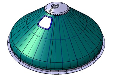
To test the use of composites in the ETF, Airbus worked with NLR to develop a 1:3 subscale version, shown here. This design rendering shows the external surface, which was fabricated using steered-tow automated fiber placement (AFP). The ETF is subject to substantial mechanical and temperature loads that pose significant design and engineering challenges. Photo Credit: Airbus Defence and Space
Being a thrust frame is not easy
As with most metal-to-composite conversions, composites can only win out on the ETF based on merit, which means the composite solution must be as or more cost-effective than the metallic predecessor, and meet or exceed metal performance metrics, specifically on mass. And the performance metrics for the ETF are not trivial.
Javad Fatemi, systems engineer at Airbus DS, working out of the organization’s Leiden, Netherlands, facility, says an upper stage ETF faces a number of performance, strength and stiffness requirements:
- Provide the attachment for mounting the engine onto the upper stage
- Transmit engine thrust to the upper stage and payload adapter
- Transmit loads during ballistic/coasting and ground phase
- Contribute to overall stiffness
- Provide accommodation, support and fixation for equipment attached/fixed to the ETF
- Provide the anchorage and enable the load transfer of the servo-actuators for the steering and control of the engine nozzle.
Fatemi adds that “the upper region of the ETF [close to the top ring] is strength-driven. This is due to the high thermal-induced stresses in the laminate as a result of the difference in the coefficient of thermal expansion [CTE] of each ply, as well as the difference of CTE between the CFRP skirt and aluminum top ring [currently most launcher fuel tanks are made in aluminum]. The ETF has to guarantee the required axial and bending stiffness, which are needed for the guidance, navigation and control [GNC] system of the rocket’s upper stage.” In addition to thermal-induced loads and ground loads, the main loads applied to ETF are engine thrust loads, servo-actuator loads and the inertial loads of equipment.
There are also significant temperature challenges associated with the ETF. Henri de Vries, senior scientist at NLR, says the temperature at the top of the ETF where it meets the upper stage can be as low as -238°C as the fuel is often stored at cryogenic temperatures; less than two meters away, where the ETF mates with the engine, the temperature can be 50°C. “That is a very short-distance, high-temperature gradient,” de Vries says.
Still, notes Fatemi, a composite ETF that meets the mechanical requirements, reduces cost and reduces weight is highly attractive. “Every kilo of weight saved goes to the payload,” Fatemi says. “We get more payload for less cost and that is critical.”
Development of a composite ETF was divided between Airbus DS NL and NLR. Airbus DS NL would provide system requirements and design, design simulation and prediction and correlation of physical testing to predicted performance. NLR would provide material and processing expertise and perform the fabrication. Most of this work was led by de Vries and Wilco Gerrits, senior R&D engineer and program manager at NLR.
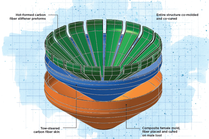
The ETF comprises two composite structures, a stiffened, structural outer skin that is designed to be fabricated via tow-steered AFP, and integral preformed stiffeners co-cured into the interior surface. Photo Credit: Airbus Defence and Space
Fatemi says the design Airbus DS NL settled on for the ETF integrates a stiffened structural skin with a series of integral, preformed stiffeners, co-cured into the inner surface of the skin. In addition, the ETF was designed with four rectangular cutouts located near the narrow end of the conical structure; the smallest one is approximately 350 x 350 millimeters and the largest one is approximately 900 x 400 millimeters. Cutouts were needed for, among other things, feed-through of fuel lines towards the engine.
Designing the ETF, selecting materials and developing fabrication technologies would be managed separately. In addition, rather than develop a full-scale ETF, Fatemi says the decision was made to evaluate the design on a 1:3 subscale version that measures 1.55 meters in diameter and 0.57 meter tall. This would require a reduction in some design elements — e.g., stringers reduced from 40 to 22, thickness reduced by half, one cutout instead of four — but would provide the data needed to assess the overall viability of the design while being a cost-effective project.
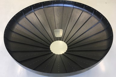
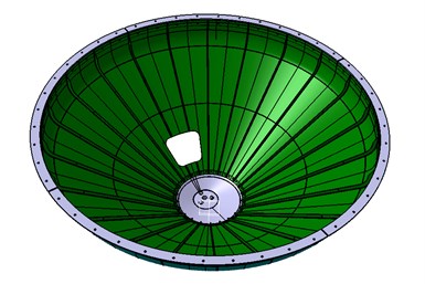
The finished prototype of the ETF subscale version features 22 interior stiffeners instead of the 40 in the full-scale version. The smaller structure also did not allow the inclusion of the integrated grid stiffeners on the interior skin. Photo Credit: Airbus Defence and Space
Complex skin
The skin would prove to be the most challenging part to design. Gerrits says NLR decided early on that it would employ automated fiber placement (AFP) in an out-of-autoclave (OOA) process which, combined with the mechanical and temperature requirements of the part, guided the material selection process. Thermal cycling, microcracking and buckling were the primary concerns, says de Vries. Further, he notes, highly stiffened forms tend to microcrack, thus the stiffness-driven design parameters only elevated this challenge.
Six materials were initially assessed; Gerrits says NLR and Airbus DS NL eventually settled on a prepreg that comprises Hexcel’s (Stamford, Conn., U.S.) IM7 intermediate modulus (IM) carbon fiber and Solvay Composite Materials’ (Alpharetta, Ga., U.S.) CYCOM 5320-1 toughened epoxy.
With a material chosen, the next challenge was to apply it. Use of AFP on a conical structure like the ETF demands use of tows steered from the wide end of the ETF at an angle over the straight edge and onto the sloping conical section. Special scripts, developed by NLR as part of the FE model for optimization of the ETF, generate a vector field with preferred fiber directions for each steered ply. Fiber placement simulation software translated the vector field into fiber placement paths to be followed by the fiber placement robot head, taking into account manufacturing constraints for the selected material (0.25-inch-wide tows). Deviations from the AFP simulation caused by manufacturing constraints (e.g., minimum steering radius) in comparison with the original vector field were fed back to the FEM to close the final design loop for the best prediction in structural behavior of the optimized ETF. Each ply placed for the skin is steered in the opposite direction of the ply it covers.
Gerrits says NLR assessed steering and application of 0.125- and 0.25-inch tows using a Coriolis (Queven, France) eight-tow AFP machine. Fatemi says Airbus DS, with NLR and others, has spent eight years performing research of tow steering, learning how to avoid the laps, gaps and wrinkles that steering can create.
“We had to fine-tune fiber placement to meet stiffness requirements,” Gerrits notes. “The whole puzzle for the design optimization [NLR’s part] was to find the right tuning buttons to adapt the timing of failure modes — in our example, buckling of the stiffener versus material failure in the stringer run out. Both are optimal when they occur just after reaching ultimate load. Modifications to the first are influencing the other. Finally, a solution was found with all failure modes very close but after reaching ultimate load. That was the whole puzzle. How to deal with external and internal pressures so that the composite does not buckle.”
Moreover, Gerrits says, manufacture of the 1:3 subscale design presented challenges of its own. “Manufacturing constraints are not scalable when working with the same material [0.25-inch tape] and technology [AFP],” he says. “The challenge was to design a 1:3 scaled ETF that behaves the same under loading at cryogenic conditions as the full scale [design], while respecting the not-scalable manufacturing constraints in combination with scaled geometry, which gave a higher degree of curvature.”
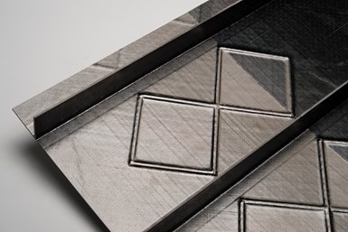
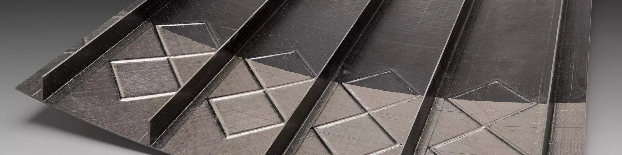
This test panel shows the “smart overlapping” technology that NLR developed for the stiffened structural skin of the full-scale version of the ETF. Smart overlapping involves strategic use of AFP to build a series of integrated square grid stiffeners. Photo Credit: Airbus Defence and Space
Smart overlapping
Designed and fabricated separately was the inner structure, comprising the 22 stringers in the 1:3 design and 40 in the 1:1 design. The 1:1 design also envisions that each stringer will be anchored to a carbon fiber laminate that features a series of integrated square grid stiffeners, manufactured using what NLR calls “smart overlapping.”
In smart overlapping, the AFP machine performs three basic tasks. The first is that it lays down one or more continuous plies of carbon fiber. Next, the AFP system is programmed to cut carbon tows mid-ply in a pattern that creates, in effect, a series of 100 x 100-millimeter tow-less squares. These squares are covered by fiber-placed patches, which are slightly bigger than the square they cover, creating an overlap in the same squared pattern. These overlaps increase the local laminate thickness, forming the integrated square grid stiffener.
In between these steps, continuous tows are placed over the entirety of the squares, which generates additional height and stiffness and creates a ridge at the edge of each square. As more tows are placed, this ridge grows in height, becomes more pronounced and completes the square grid stiffener. Says Gerrits: “As long as the overlap has sufficient length, the load transition can be maintained, with the difference that extra material [thickness] is added, resulting in an increased buckling stiffness of the laminate.”
Airbus Defence and Space Netherlands, the Royal Netherlands Aerospace Centre – NLR and the European Space Agency collaborated on development of the subscale ETF.
The lack of space in the 1:3 ETF design did not allow NLR to build these stiffeners in the structure it fabricated, but Gerrits and de Vries say that their team did fabricate single, curved compression panels that incorporated such grid stiffeners in between blade stiffeners. Tests of these structures indicate that the 1:1 design would benefit greatly from such a design by increasing post-buckling stiffness of the skin by 5%, which was sufficient for the current design. Gerrits says higher rates are possible by further increasing the height of the integrated grid stiffeners.
Lining this grid-stiffened inner skin are the U-shaped stringers, preformed via a hot-forming process and positioned with caul plates and stringer stiffeners. This entire inner structure was then nested into the inner surface of the outer skin, which in turn was nested into a female mold. This complete assembly was then vacuum bagged and oven cured to create the final co-cured structure.
Fatemi says the results of the design and fabrication of a 1:3 version of the ETF were promising enough that the fabrication of a 1:1 design is warranted. Airbus Defence and Space Netherlands is now consulting with launch vehicle manufacturers to assess the composite ETF’s viability in next-generation rocket designs.


Related Content

PEEK vs. PEKK vs. PAEK and continuous compression molding
Suppliers of thermoplastics and carbon fiber chime in regarding PEEK vs. PEKK, and now PAEK, as well as in-situ consolidation — the supply chain for thermoplastic tape composites continues to evolve.
Read More
Plant tour: National Institute for Aviation Research, Wichita, Kan., U.S.
NIAR, located at Wichita State University in the heart of the American aerospace manufacturing industry, has evolved to become a premier hub of teaching, R&D, creativity and innovation.
Read More
Optimizing AFP for complex-cored CFRP fuselage
Automated process cuts emissions, waste and cost for lightweight RACER helicopter side shells.
Read More
The potential for thermoplastic composite nacelles
Collins Aerospace draws on global team, decades of experience to demonstrate large, curved AFP and welded structures for the next generation of aircraft.
Read MoreRead Next

Composites design helps nano-sized lunar rover hit big milestones
Developed by Carnegie Mellon University, the ultralight, composites-intensive Iris nano-rover will make its lunar debut later this year.
Read More
From the CW Archives: The tale of the thermoplastic cryotank
In 2006, guest columnist Bob Hartunian related the story of his efforts two decades prior, while at McDonnell Douglas, to develop a thermoplastic composite crytank for hydrogen storage. He learned a lot of lessons.
Read More