
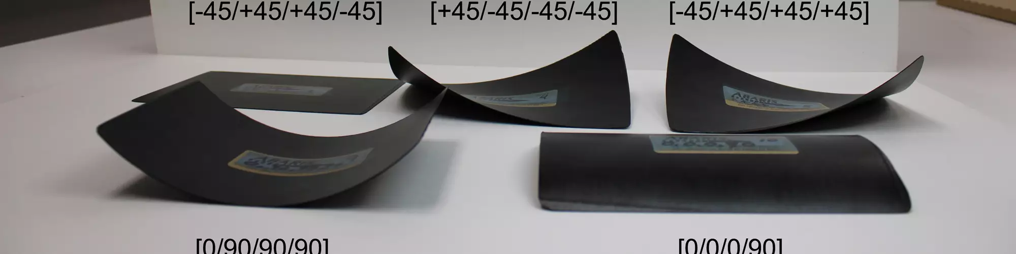


Fig. 1. CFRP J-frames for installation into lower skin section of Lear Fan fuselage assembly. Photo Credit: Lear Fan LTD and Abaris
From time to time, clients will contact me to discuss a problem they are having with a composite part that is not meeting the dimensional requirements called out on the drawing. When troubleshooting the problem, I will first ask to see two things: A photo or drawing of the part configuration and a copy of the ply table related to the layup of the part. Once it is determined that it is not a laminate springback issue (or other tooling concern), we turn the focus to the ply orientation scheme and the fiber form(s) employed in the layup. Manifestations of this issue have plagued the composites industry since my early career and continue to this day.
The first experience I had with major dimensional problems in a carbon fiber-reinforced epoxy part was back in the early 1980s. Our tooling group was tasked to build a set of composite molds for multiple “J”-frame sections for the Lear Fan 2100 all-carbon fiber fuselage (Fig. 1). We completed the tools and sent them to production, where they were used to make a set of pre-production parts, built with 8 plies of 3K, 8-harness-satin (HS) fabric and autoclave-cured at 350°F (177°C) and 90 psi. However, as the vacuum bag was removed from the first part, it demolded itself, looking more like a carbon fiber curly fry than the fuselage frame section it was intended to be. Of course, the production department pointed to the tooling as the culprit, but after further investigation, and much discussion with the M&P group, it became apparent that the root cause was something other than the tooling. But what was it?


After much deliberation, the theory put forth was that the coefficient of thermal expansion (CTE) of the carbon fiber in the cross section had a positive value (expands), while in the linear direction it had a negative value (shrinks) at the 350°F (177°C) cure temperature, thus “locking in” the fibers in this state at vitrification. The laminate then experiences a differential temperature of -280°F (-138°C) during cooldown to room temperature, ~70°F (21°C). At this point, the fibers want to return to their previous size while the resin slightly shrinks, causing increased stresses within the laminate and warpage, as depicted in the examples in Fig. 2. How do you remedy this?
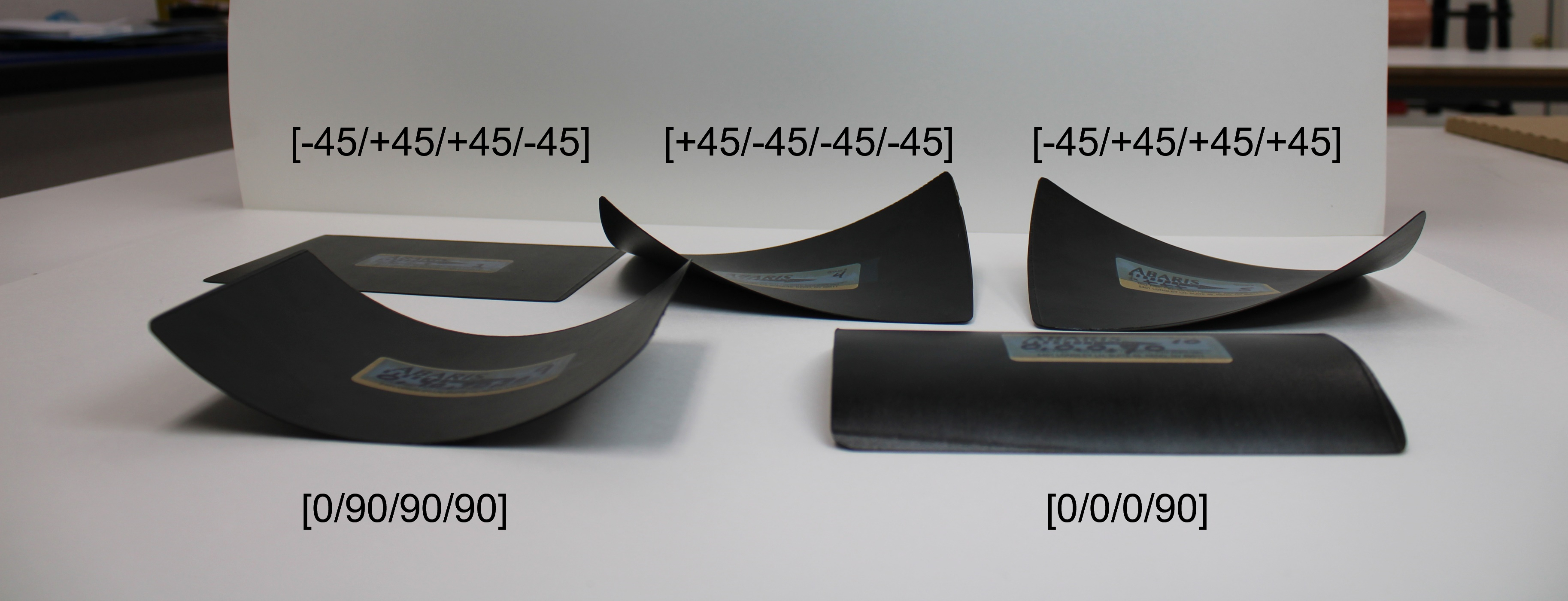
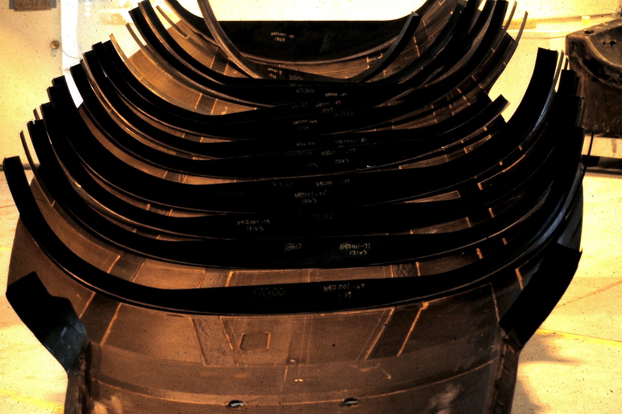
Fig. 2. Four-ply CFRP unidirectional (UD) tape panels with symmetric and asymmetric layup schemes as shown. Note that the symmetric panel is flat as molded, and the asymmetric panels are warped about the dominate axis of orientation. Photo Credit: Abaris
It was determined that the asymmetric1 orientation scheme itself, [0↓/+45↓/90↓/-45↓/0↓/+45↓/90↓/-45↓], with all plies warp face down (indicated by arrow ↓), was problematic in that it did not compensate for thermally induced forces. It was clear that opposing forces were needed within the laminate design to offset the effect and maintain a balanced2 orientation with quasi-isotropic3 properties. A new orientation scheme was introduced, [0↓/+45↓/90↓/-45↓/-45↓/90↓/+45↓/0↓], resulting in a cured part that still had a slight twist in it from end to end. Why?
A closer look at the 8HS carbon fabric itself would shed more light on the cause. One side of the fabric has yarns running in the warp direction and the other side has them running perpendicular — 90° opposite of each other in the fill (or weft) direction. This is true for all HS weave fabrics (Fig. 3). This means that the orientation (up or down) of the warp face of each ply must also be controlled along with the fiber axial direction in the layup to produce a truly symmetric laminate: [0↓/+45↓/90↓/-45↓/-45↑/90↑/+45↑/0↑]. This scheme produces a dimensionally accurate part.
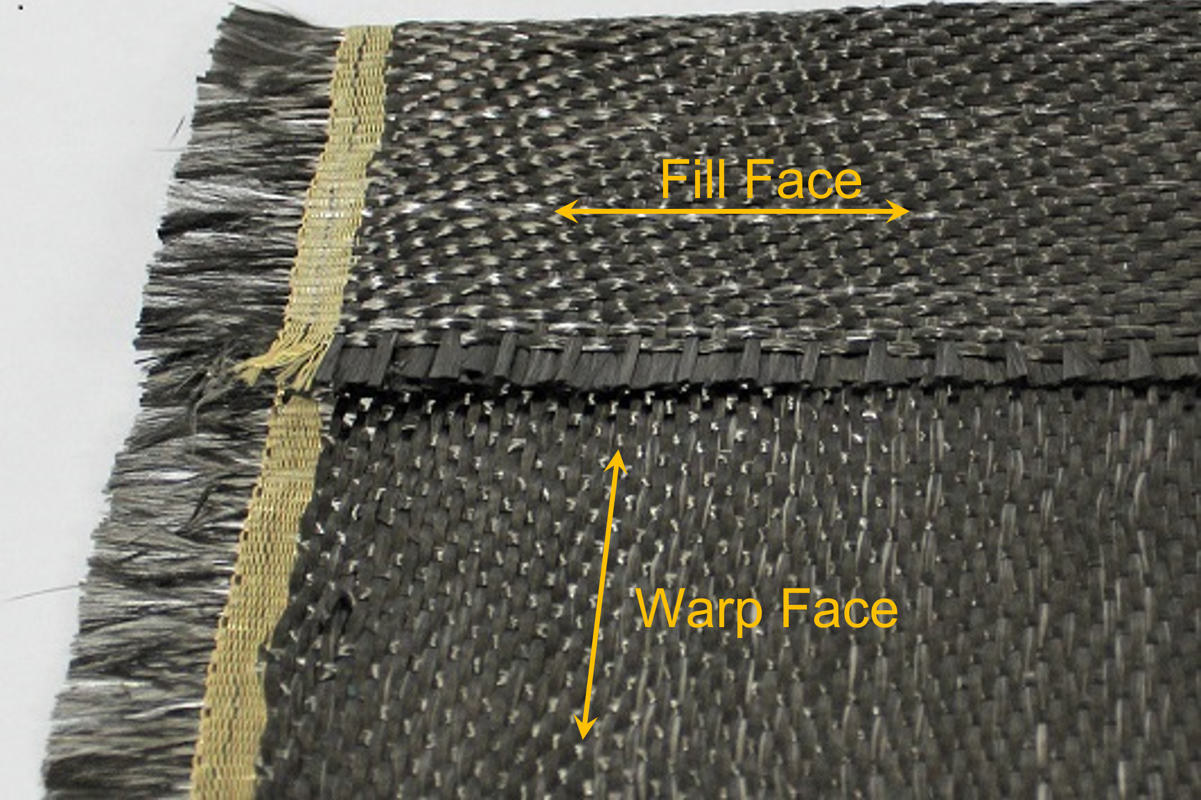
Fig. 3. This 6K 5-HS fabric shows warp face and fill face characteristics. The warp yarn direction is parallel to the length of the roll (parallel to yellow Kevlar selvedge), and the fill yarn direction is perpendicular. Warp face orientation needs to be considered when cutting plies prior to layup. Photo Credit: Abaris
This effect is most dramatic with carbon fiber unidirectional (UD) tape and HS weave fabrics. It does not apply to plain and twill weave fabrics that have an equal amount of fiber (yarns) running in both the warp and fill directions on both sides of the fabric. Therefore, warp face control with these fabrics are not required.
What about glass fiber, which has a positive CTE value when heated and expands in both linear and cross-sectional directions? Glass fiber has an average CTE that is approximately four to five times greater than carbon fiber. Therefore, each ply of HS weave glass fabric is also considered asymmetric and still can contribute to part warpage (Fig. 4). Since glass fiber has a lower modulus, thin laminates made with glass fiber reinforcements can often be forced to conform to shape with minimal load, while laminates made with higher modulus carbon fibers cannot.
Fig. 4. A single layer of #1581 style glass (8HS), used as a bleeder layer in a circular composite repair scheme, shows the effect of asymmetry after an elevated temperature cure at 250°F (121°C), subsequently cooled to room temperature. Photo Credit: Abaris
There are other considerations when using HS weave fabrics, one of which includes having fibers running on the same axis at each possible interface (nesting). This applies to layers of opposite axes that are adjacent to each other in the ply layup scheme. The idea is that nesting improves the (axial) load transfer between layers as depicted in Fig. 5, making for a more efficient laminate. Another requirement is that all laminates made with HS fabrics technically need to be designed with an even number of plies, otherwise, the laminate will be asymmetric. In addition, designers need to recognize that HS fabrics are not symmetric, even though they have equal yarn size and count in both the warp and fill directions. The outermost faces of the laminate will have greater stiffness in the dominant fiber axis compared to that of a plain (or twill) weave fabric that provides uniform stiffness.
Fig. 5. This illustration depicts an optimized layup scheme that takes advantage of nesting at five of the seven interfaces in this theoretical 8-ply laminate. Photo Credit: Abaris
While the composite industry generally has a fundamental understanding of basic fiber orientation and laminate symmetry, many designers overlook the intrinsic asymmetry of certain fiber forms such as HS (and stitched multiaxial) fabrics that can lead to dimensionally inaccurate parts. Paying attention to the type, orientation and interaction of fiber reinforcements early in the design stage can go a long way toward avoiding thermal stresses that can lead to warpage in the finished structure.


.jpg;maxWidth=300;quality=90;format=webp)


Related Content

Large-format 3D printing enables toolless, rapid production for AUVs
Dive Technologies started by 3D printing prototypes of its composite autonomous underwater vehicles, but AM became the solution for customizable, toolless production.
Read More
Manufacturing the MFFD thermoplastic composite fuselage
Demonstrator’s upper, lower shells and assembly prove materials and new processes for lighter, cheaper and more sustainable high-rate future aircraft.
Read More
Composite rebar for future infrastructure
GFRP eliminates risk of corrosion and increases durability fourfold for reinforced concrete that meets future demands as traffic, urbanization and extreme weather increase.
Read More
Novel dry tape for liquid molded composites
MTorres seeks to enable next-gen aircraft and open new markets for composites with low-cost, high-permeability tapes and versatile, high-speed production lines.
Read MoreRead Next

CW’s 2024 Top Shops survey offers new approach to benchmarking
Respondents that complete the survey by April 30, 2024, have the chance to be recognized as an honoree.
Read More
From the CW Archives: The tale of the thermoplastic cryotank
In 2006, guest columnist Bob Hartunian related the story of his efforts two decades prior, while at McDonnell Douglas, to develop a thermoplastic composite crytank for hydrogen storage. He learned a lot of lessons.
Read More
Composites end markets: Energy (2024)
Composites are used widely in oil/gas, wind and other renewable energy applications. Despite market challenges, growth potential and innovation for composites continue.
Read More