
Compression platens and subpresses
Dr. Don Adams discusses the use of compression platens (fixed and spherical seat) and subpresses to ensure reliable test frame operation.
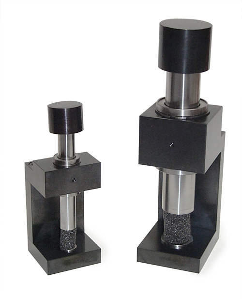
Fig. 4: Compression subpresses (25-mm/1-inch and 50-mm/2-inch diameters).
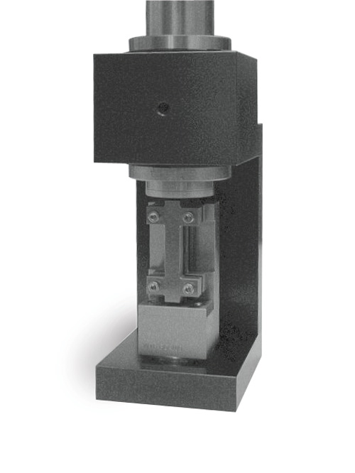
Fig. 5: A compression subpress with a Modified D695 Open Hole Compression test fixture in place.
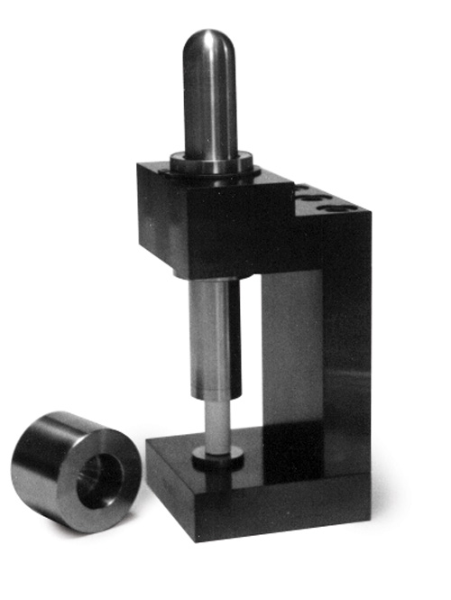
Fig. 3: A compression subpress, with a 25-mm/1-inch platen diameter.
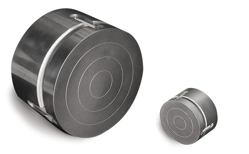
Fig. 2: Spherical seat platens (150 mm/6 inch and 65 mm/2.5 inch diameter).
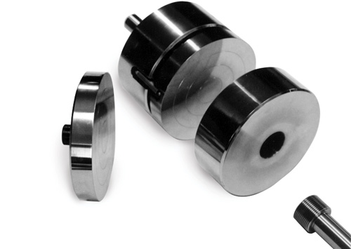
Fig. 1: Fixed and spherical seat platens.


Many mechanical tests of composite materials require the compression loading of a test fixture. These include not only compression test methods, but also many shear, flexure, curved-beam strength, fastener pull-through, fracture toughness and other test methods. Often, these fixtures are simply placed between two flat surfaces and loaded in compression. In a universal testing machine, these flat surfaces are provided by essential accessories called compression platens.
Two basic types of compression platens are used, fixed and spherical seat. Both types are represented in Fig. 1. Those shown are 150-mm/6-inch diameter platens, a popular size because it represents a good tradeoff between capacity, weight and cost. The 150-mm/6-inch diameter spherical seat platen (top center) weighs about 14 kg/31 lb. Weight and cost increases rapidly as the diameter is increased. Smaller diameters can be used if the application permits.


The platens at left and right in Fig. 1 are fixed platens. As indicated in the photograph, an attachment method is provided to rigidly connect the platen to the testing machine. For example, at the lower right corner is an adapter that can be threaded into the platen. Its other end is a smooth stud that can be held in the V-grips of the testing machine. The platen in the top center of Fig. 1 and those in Fig. 2, are spherical seat platens. These typically consist of two thick disks held in contact with each other by springs, as shown. One of the contacting surfaces has a shallow hemispherical cavity in its surface. The other has a mating hemispherical protrusion. Thus, one plate can be fixed to the testing machine, leaving the other plate is free to swivel.
The very shallow concentric grooves on the working faces of the platens are intended as a visual aid when positioning the specimen or test fixture in the center of the platen. The working faces must be very hard so that the object under compression does not damage them. Thus, platens are typically fabricated of case-hardened, or even better, through-hardened alloy steel. It also is customary for commercial suppliers to chrome plate the entire platen. Although plating is unnecessary in terms of damage prevention if the platens are already hardened, it does add rust- and corrosion-resistance.
There are specific applications where only one compression platen is required, for example, to provide a solid base upon which to support a test fixture attached directly to the testing machine at its upper end. A fixed platen would typically be used in this case.
When the application requires two platens, top and bottom, with the specimen or a test fixture compression loaded between them, two fixed platens might be preferred. If these two fixed platens are well aligned in an adequately stiff testing machine, they provide loading surfaces that remain parallel to each other and perpendicular to the axis of the testing machine, the desired conditions for compression loading. An alternative is to use one fixed platen (usually on the bottom) and one spherical seat platen. Then the spherical seat platen can swivel as required to make full contact with what it is loading, making initial alignment less critical. Which combination is best usually depends on the application and testing machine characteristics. However, a significant, nontechnical consideration is that spherical seat platens typically cost more than three times as much as fixed platens. When neither combination is suitable, because of testing machine deficiencies, it might be desirable to add a compression subpress.
A compression subpress is a self-contained unit, placed between two platens within the testing machine. This device is designed to provide loading surfaces that will remain parallel to each other and perpendicular to the specimen’s loading axis, independent of the testing machine characteristics. The subpress must be sufficiently rigid so that it does not distort unacceptably under load. Also, the loading surfaces (that is, the surface at the lower end of the loading rod and the surface of the base anvil) must be fabricated of very hard materials so that they are not indented or otherwise deformed by the specimen when concentrated loads are applied.
One such test fixture is shown in Fig. 3. The spherical cap on top of the spherical-end loading rod (shown removed in the photo) ensures that any misalignments of the testing machine are not transmitted to the subpress. A linear (ball bearing) bushing in the upper portion of the subpress frame maintains the alignment of the loading rod during axial movement, minimizing friction by providing rolling rather than sliding contact with the rod. Compression subpresses are available in various sizes. The fixture in Fig. 3 has a 25-mm/1-inch diameter loading rod and anvil, fabricated of steel, with hardened tool steel loading surfaces.
In Fig. 4, a 25-mm/1-inch diameter subpress like the one shown in Fig. 3 is shown to the left of a 50-mm/2-inch model. Obviously, the latter can apply much greater loadings to larger specimens, but it is much heavier, more awkward to work with, and more expensive. In addition to size, the general configuration of the subpress can be modified, for example, to accommodate very tall specimens or short specimens while keeping the length of the loading rod as short as possible.
Compression subpresses also help ensure that a separate test fixture used to apply a compressive load to the specimen is applying that load axially (as in Fig. 5). A Modified D 695 Compression Test Fixture (see "Editor's Picks" under “Learn More,” at right) is mounted in the 50-mm/2-inch diameter subpress. The top end of the specimen projects above the Modified D 695 fixture when clamped in position between the two I-shaped lateral support plates. Thus, it is end-loaded by whatever device is used to apply the force. If the specimen is loaded directly by the test machine platens, the uniformity of loading is dependent on the alignment of the testing machine and platens, as previously discussed. By mounting the Modified D695 fixture in a compression subpress, which in turn is mounted in the testing machine, the influence of testing machine misalignments is eliminated.


.jpg;maxWidth=300;quality=90;format=webp)


Related Content

Materials & Processes: Tooling for composites
Composite parts are formed in molds, also known as tools. Tools can be made from virtually any material. The material type, shape and complexity depend upon the part and length of production run. Here's a short summary of the issues involved in electing and making tools.
Read More
JEC World 2022, Part 3: Emphasizing emerging markets, thermoplastics and carbon fiber
CW editor-in-chief Jeff Sloan identifies companies exhibiting at JEC World 2022 that are advancing both materials and technologies for the growing AAM, hydrogen, automotive and sustainability markets.
Read More
Thermoset-thermoplastic joining, natural fibers enable sustainability-focused brake cover
Award-winning motorcycle brake disc cover showcases potential for KTM Technologies’ Conexus joining technology and flax fiber composites.
Read More
Thermoplastic composites welding: Process control, certification, crack arresters and surface prep
More widespread use of welded composite structures within a decade? Yes, but further developments are needed.
Read MoreRead Next

Open-hole compression testing
By the early 1980s, the emphasis was shifting from development of composite materials to development of tough, durable composite materials. The common catch phrase that emerged was "effects of defects." This new emphasis on toughness dictated the development of test methods that could measure this material
Read More
Composites end markets: Energy (2024)
Composites are used widely in oil/gas, wind and other renewable energy applications. Despite market challenges, growth potential and innovation for composites continue.
Read More
CW’s 2024 Top Shops survey offers new approach to benchmarking
Respondents that complete the survey by April 30, 2024, have the chance to be recognized as an honoree.
Read More