
Open-hole compression testing
By the early 1980s, the emphasis was shifting from development of composite materials to development of tough, durable composite materials. The common catch phrase that emerged was "effects of defects." This new emphasis on toughness dictated the development of test methods that could measure this material


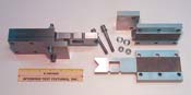
Source: Don AdamsFig 1: The Boeing Open-Hole Compression Test Fixture, shown partially disassembled.
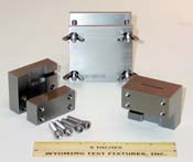
Source: Don AdamsFig 2: The Northrop Open-Hole Compression Test Fixture, shown partially disassembled.

The founder and president of Wyoming Test Fixtures Inc. (Laramie Wyo.), Dr. Donald F. Adams holds a BS and an MS in mechanical engineering from, respectively, the University of Illinois and the University of Southern California, and a Ph.D in theoretical and applied mechanics (University of Illinois). Following service with Northrop Aircraft Corp., the Aeronutronic Div. of Ford Motor Co. and the Rand Corp., he joined the University of Wyoming in 1972, directing its Composite Materials Research Group for 27 years. Dr. Adams continues to write, teach and serve with numerous industry groups, including the test methods committees of ASTM and MIL-HDBK-17.
By the early 1980s, the emphasis was shifting from development of composite materials to development of tough, durable composite materials. The common catch phrase that emerged was "effects of defects." This new emphasis on toughness dictated the development of test methods that could measure this material property.
Defects can occur naturally during composite fabrication, and damage can be induced by impacts in service, but these tend to be relatively uncontrolled events. It was desired to induce an easily reproducible defect and, obviously, one reasonably representative of a service environment. This led to the tensile or compressive test of a specimen containing a carefully drilled hole. This method provides a controlled simulation of a natural defect in a composite structure, but can double as a method for testing fastener holes as well.


Compression loading can be particularly susceptible to defects, due to the tendency for local delaminations to induce buckling failures. For that reason, it was especially important to develop open-hole compression test methods. Response to an open-hole is emphasized here to distinguish it from the different (although also important) compressive response of a composite laminate structure assembled with fasteners (bolts or rivets) that fill the hole and thus can transmit load across the hole.
Recognizing the need for new toughness test methods, NASA Langley conducted a workshop in 1981, and organized a continuing effort to standardize an open-hole compression test method, as well as other test methods designed to quantify the toughness of a composite laminate. The outcome was a NASA test specimen 127 mm/5-inches wide, containing a centrally located, 25.4-mm/1-inch diameter hole (NASA Reference Publication 10921). The quasi-isotropic laminate [45/0/-45/90]ns was relatively thick -- nominally 6.4 mm/0.25 inch), the same as the compression-after-impact and open-hole tensile test specimens also being developed at the time. Likewise, the same test fixture was used to test both compression-after-impact and open-hole compression specimens, this fixture being designed to accommodate 318-mm/12.5-inch long specimens.
This 318-mm long by 125-mm wide by 6.4-mm thick open-hole compression specimen obviously consumed a large amount of material per specimen. This could be a problem, especially for material development programs, where the new material being developed was typically in short supply. Thus, the composites industry very quickly reduced the "standard" specimen size. In fact, by early 1982, Boeing had already adopted a smaller specimen2, which also was adopted as the "standard" by NASA in a second committee report in 19853, SACMA in 19884, Hercules in 199015 and other groups as well. This was a specimen 305-mm/2-inches long but only 38-mm/1.5-inch wide, and on the order of 2.5-mm/0.10-inch thick, with a centrally located, 6.3-mm/0.25-inch diameter hole. This is the nominal specimen size still used by the industry today.
Boeing2 also developed a different method of specimen anti-buckling support than had been proposed by the initial NASA-sponsored studies. The specimen was face-supported rather than edge-supported (although the Boeing compression-after-impact specimen is, today, still edge-supported). This Boeing open-hole compression support fixture also was generally adopted by the industry as a whole.
Although ASTM International (W. Conshohocken, Pa.) studied the possibility of standardizing the Boeing specimen and fixture as early as 19906, the test method wasn't officially adopted until 2000 (the resulting ASTM Standard D 64847 uses a configuration identical to Boeing's). By then, the "Boeing Open-Hole Compression" test method was already widely used. The original Boeing specification, BSS 72602, which had become a de facto industry standard, had already been superceded by Boeing D888-10026 (January 1996)8. Another Boeing document, D6-83079-71, was issued in late 20039.
It should be noted that the specimen and test fixture as presently defined in ASTM D 6484, Boeing D888-10026, and Boeing D6-83079-71 are all identical, and only insignificantly different than the original Boeing BSS 7260 configurations.
The fixture is shown in Fig. 1. It is 76-mm/3-inches wide and has a thickness of 30.5 mm/1.2 inches plus the specimen thickness. In Boeing's original concept, the fixture was loaded by clamping each end in large hydraulic wedge grips. Obviously, these grips must be a minimum of 76-mm/3-inches wide and capable of opening at least 33-mm/1.3 inches. These dimensions typically imply hydraulic grips of at least 50,000-lb capacity, a size not commonly available in many testing laboratories. As a result, laboratories without the large grips used the standard fixture, but loaded it directly on its ends between flat platens. Comparison studies10 since then have demonstrated equivalence, a fact that eventually led ASTM, in 2004, to modify ASTM Standard D 6484 to permit end loading as well.
Although the Boeing version of the open-hole compression test method has become, by far, the most widely used, a number of alternative configurations exist. Perhaps the most prominent of these is the so-called Northrop Open-Hole compression test method11, developed by Northrop Aircraft at about the same time as the Boeing method. It uses a specimen only 76-mm/3-inches long by 24.5-mm/1-inch wide, but also with a 6.3-mm/0.25-inch diameter, centrally-located hole. ASTM also considered this test method at the same time the Boeing version was being evaluated6, obtaining comparable strength values and otherwise favorable results, but did not subsequently pursue it as part of the eventual standard.
At about the time the Boeing method became an ASTM standard (i.e., in 2000), a detailed university research study was conducted, again showing that the Northrop method compared very favorably with the Boeing method10. The Northrop method has the obvious advantage of using a much smaller specimen (requiring about one-sixth as much material per specimen) and a smaller (and thus less expensive and easier to handle) fixture. It is an end-loading method, as shown in Fig. 2.
But for any test method to become an ASTM standard, or even to be widely used, it must have a "champion," i.e., an individual or group to actively promote it. Such a champion has yet to emerge for the Northrop test method.
References:
1NASA Reference Publication 1092, "Standard Tests for Toughened Resin Composites," Langley Research Center (Hampton, Va.), July 1983.
2Boeing Specification Support Standard BSS 7260, "Advanced Composite Compression Tests," The Boeing Co. (Seattle, Wash.), Original Issue, February 1982 (currently Revision C, December 1988).
3NASA Reference Publication 1142, "NASA/Aircraft Industry Standard Specification for Graphite Fiber/Toughened Thermoset Resin Composite Material," Langley Research Center (Hampton, Va.), June 1985.
4SACMA SRM 3-88, "SACMA Recommended Test Method for Open-Hole Compression Properties of Oriented Fiber-Resin Composites," Suppliers of Advanced Composite Materials Association (Arlington, Va.), April 1989 (revised as SRM 3R-94, April 1994).
5"Mechanical Test Methods for Fiber Reinforced Resin-Matrix Composites," Document E23004DT06005, Revision F, Hercules Aerospace Divisions (Magna, Utah), March 1990.
6Lubowinski, Steve, "Open-Hole and Laminate Compression Study," presentation at the ASTM Committee D30 Compression Testing Study Group (San Antonio, Texas), Nov. 14, 1990.
7ASTM Standard D 6484-99, "Open-Hole Compressive Strength of Polymer Matrix Composite Laminates," American Society for Testing and Materials (W. Conshohocken, Pa.), March 2000 (latest revision, D 6484-04, April 2004).
8"Test Methods for Advanced Composites," Document 888-10026, L-22 Corporate Composite Standardization Initiative, The Boeing Co. (Seattle, Wash.), Revision A, January 1996.
9"Test Method for Compressive Properties of Thin Composite Lamina and Laminates," Document D6-83079-71, Boeing Commercial Airplanes (Seattle, Wash.), November 2003.
10Coguill, S.L., and Adams, D.F., "A Comparison of Open-Hole Compression Fixtures by Experimental Evaluation," Proceedings of the 45th International SAMPE Symposium (Long Beach, Calif.), May 2000, pp. 1095-1105.
11"Preimpregnated Carbon/BMI Material for 375°F Service," Document NAI-1504, Northrop Corp., Aircraft Div. (Hawthorne, Calif.), Revision C, May 1988.


.jpg;maxWidth=300;quality=90;format=webp)


Related Content

Cryo-compressed hydrogen, the best solution for storage and refueling stations?
Cryomotive’s CRYOGAS solution claims the highest storage density, lowest refueling cost and widest operating range without H2 losses while using one-fifth the carbon fiber required in compressed gas tanks.
Read More
Novel dry tape for liquid molded composites
MTorres seeks to enable next-gen aircraft and open new markets for composites with low-cost, high-permeability tapes and versatile, high-speed production lines.
Read More
Plant tour: Spirit AeroSystems, Belfast, Northern Ireland, U.K.
Purpose-built facility employs resin transfer infusion (RTI) and assembly technology to manufacture today’s composite A220 wings, and prepares for future new programs and production ramp-ups.
Read More
Materials & Processes: Resin matrices for composites
The matrix binds the fiber reinforcement, gives the composite component its shape and determines its surface quality. A composite matrix may be a polymer, ceramic, metal or carbon. Here’s a guide to selection.
Read MoreRead Next

CW’s 2024 Top Shops survey offers new approach to benchmarking
Respondents that complete the survey by April 30, 2024, have the chance to be recognized as an honoree.
Read More
From the CW Archives: The tale of the thermoplastic cryotank
In 2006, guest columnist Bob Hartunian related the story of his efforts two decades prior, while at McDonnell Douglas, to develop a thermoplastic composite crytank for hydrogen storage. He learned a lot of lessons.
Read More
Composites end markets: Energy (2024)
Composites are used widely in oil/gas, wind and other renewable energy applications. Despite market challenges, growth potential and innovation for composites continue.
Read More