
Aircraft simulation gets composites aware
Rapid software evolution enables faster, better virtual solutions to complex composite design problems.
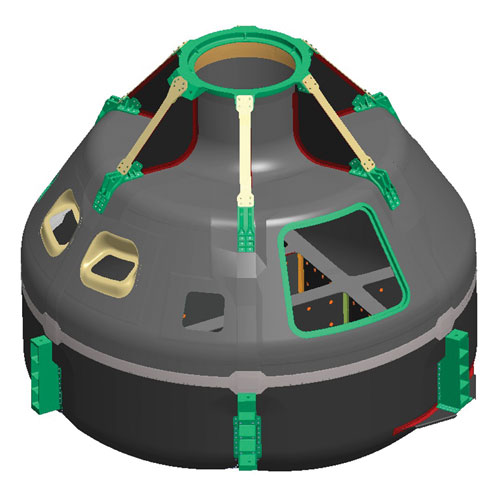
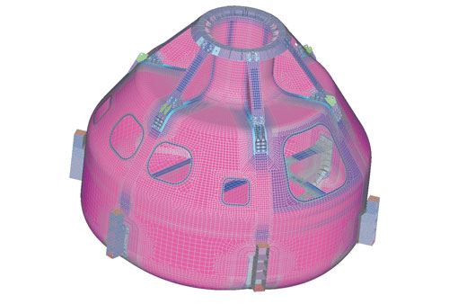
CCM demonstrator: For the Orion space program, a NASA Langley Engineering and Safety Center team is building a nonflying, demonstration Composite Crew Module (CCM), using MD Nastran to calculate internal loads during simulated launch and flight, and HyperSizer for ply-by-ply strains, failure indices, and to optimizing the design. Source: NASA
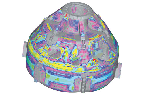
Revealing safety margins: This view depicts the resulting analytical safety margins for each region identified for the CCM test article. Again, each color is keyed to a color-coded scale. Source: NASA
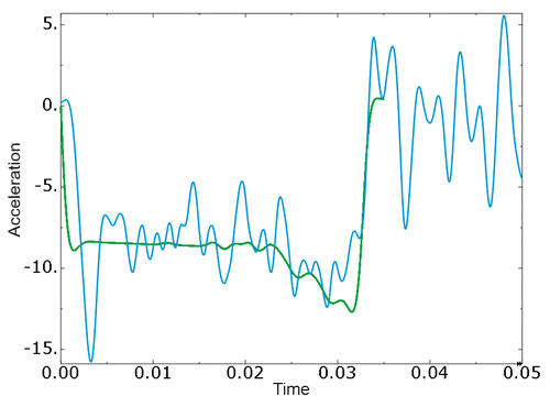
Physical test results compared to software-generated prediction.
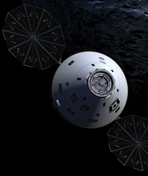
Modeling the future: Software that can accurately model composite structures and simulate their behavior under load stress and strain is enabling aerospace engineers to cost-efficiently design next-generation aerospace vehicles, such as this prospective crew capsule being developed in conjunction with NASA’s Orion space program. Source NASA
Defining the facesheets: This view of the model depicts the thickness of the carbon fiber/epoxy facesheets in the sandwich structure of the NASA CCM structural test article. Facesheet thickness is color-coded to a thickness scale. Source: NASA
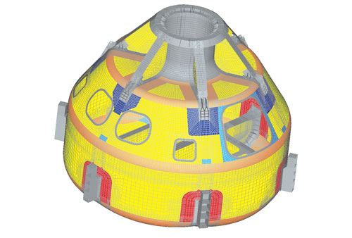
Defining the core: This meshed image depicts regions of nominal 1-inch/25.4-mm thick aluminum honeycomb densities within the carbon fiber/epoxy sandwich structure of the CCM test article. Each color represents a different core density or type. Regions in which the core tapers and the facesheets join into solid laminate are indicated by the color grey. Source: NASA
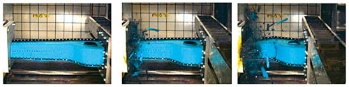
Crush zone performance: A mass of 1150 kg moving at an initial velocity of 9.1 m/s impacts a complex composite cone structure in an experimental sled test. Crushing of the cone progresses to a point where a large fracture develops suddenly in the transition region between the cone and its backup structure. Results from virtual testing in SIMULIA’s (Providence, R.I.) CZone for Abaqus accurately predicted both the crushing response and the sudden fracture outside the crush front. Acceleration histories of the sled mass (see chart, below) correlate well when comparing experimental data (blue) against simulation results (green). Source: Dassault Systemes
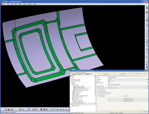
Fuselage panel: Pictured is a FiberSIM (VISTAGY Inc., Waltham, Mass.) simulation of a composite fuselage panel during a CAD modeling session. FiberSIM automatically generated ramp surfaces (pictured in green) between ply zones. Because it can handle multidirectional curvature and allows filleting of the ramp sections, it can model an accurate surface for the creation of tooling. Source: VISTAGY Inc.


Software-based simulation and modeling tools for aircraft can be divided, roughly, into three interrelated functional categories: design and model building, analysis or problem solving, and manufacturing. Although each is critical to modern aircraft construction, analysis — specifically, finite element analysis (FEA) — has played, arguably, the most significant role in making possible the ever-increasing use of composites in aircraft design.
Composites manufacturers are familiar with FEA as a software program, but FEA is first and foremost a mathematical method. It has its roots in the 1940s, when civil and aeronautical engineers first sought better means to solve complex elasticity and structural analysis problems. They devised ways of “meshing” or partitioning a continuous domain (e.g., a wing surface) into a set of discrete subdomains called elements. Then a numerical technique for finding approximate solutions to partial differential equations that represented each element was developed to simulate bending, twisting, buckling and other damage that a physical structure might incur in service. This enabled the user to analyze the distribution of loads and stresses, improve the structure’s design and minimize weight before a prototype was built (see “Learn More,” at right). Testing a part, element by element, with this methodology was time consuming, but it vastly reduced the cost associated with “making and breaking” a long series of physical prototypes.


While FEA pioneers shared a common objective, they took different approaches. As their various mathematical methods were computerized — accelerating calculations and eventually permitting engineers to display meshed models graphically — this diversity remained: The equations, what they describe, the methods used to solve them, and the ways they are translated into computer code give each of today’s FEA-based modeling/simulation tools unique features and capabilities. These differences, however, also made it difficult to take advantage of that diversity because data produced in one program had to be manually translated to another program.
As OEMs, particularly in the aircraft world, transitioned from metals to composites, FEA-based modeling and simulation programs that were originally written for homogenous metals had to be adapted for use with heterogeneous composites.
To accomplish these ends, software writers have developed tools that simplify or eliminate tool-to-tool translation and account for the greater structural and behavioral complexity of multilayered fiber/resin laminates and cored sandwich laminates.
Tools that reflect composite realities
MSC.Software Corp. (Santa Ana, Calif.), for example, has expended considerable effort to understand and model the physics of composites aging, a process that is far more complex and time-consuming than simulating metal aging. Metal fatigue can be simulated by equations that describe macroscopic mechanics, but predicting fatigue in a composite requires equations at the mesoscopic or grain-size level because the engineer must have the ability to detect microscopic failures in specific composite materials and structures. Reza Sadeghi, MSC.Software’s chief technology officer, calls the mathematics “daunting.” If testing goes well, the company expects to release the feature in MD Nastran sometime in 2009.Altair Engineering’s (Troy, Mich.) OptiStruct, on the market since 1997, has been used primarily by major aerospace companies to optimize metal-part structural design. About a year ago, Altair introduced new “ply-based modeling” capabilities that facilitate composite component optimization. Robert Yancey, Altair’s managing director, western U.S. and business development director, composites, says a generic setup for the composites optimization program would run as follows: Define the shape of the composite laminate; define loads and boundary conditions on the laminate; define the objective (e.g., minimum weight) and constraints (e.g., limit on strain); and define the ply-orientation angles to be considered. OptiStruct will then specify how many plies of each angle orientation will be required in the laminate to meet the objective and constraints, as well as where the plies will need to be built up or down.
Altair also will incorporate ply-based modeling into its FEA pre- and postprocessing program, HyperMesh v10, scheduled for release in March or April 2009. Altair’s Yancey says that traditional FEA models for composites are based on individual elements rather than plies. In a ply-based model, the composite part has a ply definition and a stack definition, which makes it easier and faster to evaluate the effect of, say, changing the dimension of a single ply. “This capability makes it much simpler to do iterative analysis on composite laminates,” he notes, adding that FEA models built in HyperMesh also can be exported to other commercial solvers, such as Nastran and Abaqus.
Elsewhere, SIMULIA (Providence, R.I.) recently released CZone for Abaqus, a new advanced composite crush-simulation tool for evaluating and improving the crashworthiness of transportation vehicles. CZone for Abaqus is an add-on to the company’s advanced FEA software package, Abaqus. Part geometry that has been designed using CAD software can be transferred to Abaqus for meshing and analysis, at which point CZone for Abaqus can be used for crush simulation and evaluation.
The core technology of CZone for Abaqus was developed by Engenuity Ltd. (West Sussex, U.K.). Engenuity has developed a methodology for simulating the crashworthiness of composite structures based on the assumption that the crush properties of a composite, like other material properties, are testable. SIMULIA has partnered with Engenuity to incorporate the technology into a fully commercial FEA package for advanced crush simulation of large composite components and assemblies.
CZone for Abaqus enables engineers to rapidly evaluate vehicle designs for crashworthiness. These simulations determine the extent of material crushing, the energy absorbed in the crush zone and the forces generated by material crushing. A proposed design can be altered quickly to optimize the placement, thickness, construction and geometry of crush structures to maximize their energy-absorbing capacity.
Kyle Indermuehle, aerospace lead for SIMULIA’s technical marketing group, reports that CZone for Abaqus’ functionality is a result of the incorporation of empirical data from material coupon testing. Coupon testing determines the strength, stiffness and crush properties of the composite materials that are being considered for the aircraft. SIMULIA has done and continues to do benchmark testing of CZone for Abaqus with the FAA-sponsored Composite Materials Handbook working group, CMH-17. The group, whose mission is the development of standards and databases for tests and characterization of composites, includes experts from industry, government and academia. A number of these benchmarks or simple test cases (one involves, for example, an automotive composite crossbeam) are included in CZone for Abaqus training as generic problems. For unique applications, users first must create their own CAD geometries and generate material-specific coupon test data, which is then used by CZone for Abaqus.
A potential application for the software is establishing crashworthiness of helicopter subframes. Helicopter manufacturers, at the behest of the military and the requirements laid out in MIL-STD 1290, have been pursuing ways to improve the crashworthiness of helicopters for two decades. Structural solutions have generally tended to be a combination of energy-absorption mechanisms in the landing gear, subfloor structure and seats. Over the years, however, it has been noted that structural solutions that improve crashworthiness on land do not work as well on water. The landing gear, for example, does not function well as an energy absorber on water impact. SIMULIA is working with the CMH-17 group and customers on this and other aerospace design cases.
“The goal in all these simulations, both benchmarks and customer-specific, is to have an overall composite design for an aircraft, helicopter or automobile that absorbs energy so that the occupants experience less G deceleration on impact,” says Indermuehle.
Many tools in one toolbox
Although simulation tools abound, they often require the attention of users who are highly skilled at building models and then virtually testing them using a series of disconnected simulation tools. The lack of data consistency and resulting inability to reuse data still makes the simulation process time consuming and disjointed. In response, one of the most marked trends in software development is toward tools integration (see “Learn More”).MSC.Software, for example, provides one of the original computer-aided simulation packages, MSC Nastran, which was codeveloped with NASA starting in the 1960s. About five years ago, the company combined MSC Nastran, along with a number of other MSC.Software analytical simulation tools, such as MSC Marc and MSC Dytran, into an integrated simulation-analytical package, MD Nastran. “MD” signifies multidiscipline simulation. In basic terms, MD Nastran will provide the stresses and loads that occur in every composite layer under various conditions. Prior to the MD platform, engineers had to export the finite element (FE) model into Dytran, for example, to simulate aircraft water landings or into Marc to analyze the effect of temperature changes on materials. MSC.Software’s Sadeghi says the net result is greatly enhanced flexibility that enables engineers to simulate and evaluate the effects of material changes, temperature changes, explosives and crash landings, as well as do resonance, dynamic, stress and other sorts of linear and nonlinear calculations, all with a single model.
Extension of FEA reach
Software tools also are available to help engineers go where current FEA programs can’t take them. “FEA’s purpose is to compute loads in the aircraft, for example, when the main landing gear hits the runway,” says Craig Collier, president of Collier Research Corp. (Newport News, Va.). “But at that point it’s not going to tell you which composite ply or layer is overstressed, and it’s certainly not going to tell you how to redesign the composite to make it lighter and still carry the load.”To that end, Collier offers HyperSizer, an automated design tool for analyzing and optimizing the strength and stiffness of stiffened panels made from any material. The software was conceived and developed at NASA’s Langley Research Center (Langley, Va.) in the early 1980s. Collier Research obtained an exclusive, all-fields-of-use license to the code (ST-SIZE) in 1996 and has been updating and expanding its utility almost continually since then, says Collier. HyperSizer supports many commercial versions of Nastran FEA simulation tools, as well as SIMULIA’s FEA software, Abaqus. It also can be coupled with various CAD packages, such as CATIA, and composite manufacturing software, such as FiberSIM.
Collier reports that NASA has begun a major initiative to reduce costs and lighten payloads through increased use of composites in future space structures. For example, a NASA Engineering and Safety Center (NESC) team at the Langley Research Center is designing and building a nonflying, demonstration composite crew module (CCM). The module, which forms the inner crew cabin or pressure vessel of the space vehicle, is based on the architecture of NASA’s Orion crew module currently being built by Lockheed Martin Space Systems (Littleton, Colo.). The module will be used to transport astronauts to the International Space Station, as well as into lunar orbit in NASA’s next lunar landing mission scheduled for as early as 2019. Both the Orion crew module and the CCM demonstrator will be similar in shape to the earlier Apollo spacecraft but significantly larger, with more than 2.5 times the interior volume of the Apollo capsule.
One project goal is to give NASA engineers hands-on experience in building habitable, composites-based space vehicles, says Mike Kirsch, principal engineer and team lead of the CCM project. The NESC team has chosen Hexcel’s (Dublin, Calif.) IM-7 carbon fiber fabric and Cytec Engineered Materials’ (Tempe, Ariz.) 977-2 epoxy resin system as the principal materials. The team uses MD Nastran to calculate internal loads and used HyperSizer to determine the ply-by-ply strains and failure indices and optimize the design.
“It [HyperSizer] is a handy tool,” says Jim Jeans, lead structural analyst, CCM project. “If you iterate four or five times, it will develop a local optimum of what your layup needs to be to support your loads with safety margins everywhere.”
Kirsch, however, notes that even the best software solutions give little guidance on how to make bonded joints and how to match up interfaces when making material trade-offs between, say, aluminum and carbon-fiber composite fabric. Part of the problem, he says, is that simulation tools are only as good as the FE models being fed into them. “Typically, at the trade-study level, the true joint details haven’t been defined sufficiently to be included in the FE models and don’t get the benefit of the structural simulation,” Kirsch says.
Automating optimization
The introduction of composites into the fuselage, wings and other aircraft primary structures, doesn’t necessarily make FE analysis more detailed than in the past, says John O’Connor, director product and marketing strategy at VISTAGY Inc. (Waltham, Mass.), but a greater number of design iterations are needed to optimize performance, weight and cost. Accordingly, the latest version of VISTAGY’s FiberSIM 5.4, features a number of new automated features that enable engineers to address layup and manufacturing issues (e.g., whether a ply layer will wrinkle or bridge on a curved surface) in the design stage rather than on the shop floor. Version 5.4 shortens the time it takes to optimize part design by enabling engineers to perform more design iterations later in the development process when they can more intelligently evaluate trade-offs between part performance, weight and manufacturing cost. Already fully integrated with commercial CAD systems, such as CATIA v5 and Pro/Engineer, FiberSIM’s new version also features a link to MSC.Software’s SimXpert finite element software. The link communicates FEA mesh information directly to design data generated in CAD. Using this feature, products can be designed, validated and optimized without having to translate volumes of data between different software tools. FiberSIM 5.4 also comes with tools that improve the ability of engineers to design for specific manufacturing processes. The software’s new functionality includes design-for-manufacturing enhancements, such as new capabilities for generating ramps between ply zones, and tools for color-coding plies based on material type or orientation. Additionally, there are features for developing complex core designs and the software can determine core splicing options that make the best use of materials and facilitate the layup process.The constant is continuous improvement
Although the acceleration in aerospace composites development in this decade is unprecedented, it’s likely just a prelude. For that reason, MSC.Software’s Sadeghi says simulation software, as a rule, is never static. Instead, it must be updated continually. “Unlike when you buy Windows Vista and download 99 percent of it onto your computer in one shot, in the world of FEA simulation, you buy a version of the software and use it as a road map,” says Sadeghi. “It’s a very continuous process.” That may make it tough for developers and users to keep up, but those who do reap the rewards. “FEA,” says Sadeghi, “allows you to have something like a magnifying glass to look into any part of a structure and ask any question you want.” And get a faster, more accurate answer.


Related Content

Why aren't composites synonymous with infrastructure?
The U.S. seems poised to invest heavily in infrastructure. Can the composites industry rise to the occasion?
Read More
CirculinQ: Glass fiber, recycled plastic turn paving into climate solutions
Durable, modular paving system from recycled composite filters, collects, infiltrates stormwater to reduce flooding and recharge local aquifers.
Read More
Gatorbar, NEG, ExxonMobil join forces for composite rebar
ExxonMobil’s Materia Proxima polyolefin thermoset resin systems and glass fiber from NEG-US is used to produce GatorBar, an industry-leading, glass fiber-reinforced composite rebar (GFRP).
Read More
Materials & Processes: Composites fibers and resins
Compared to legacy materials like steel, aluminum, iron and titanium, composites are still coming of age, and only just now are being better understood by design and manufacturing engineers. However, composites’ physical properties — combined with unbeatable light weight — make them undeniably attractive.
Read MoreRead Next

FEA Roundup: Design, Simulation And Analysis Converge
New modeling and analysis software products increase the accessibility and reliability of finite element analysis data.
Read More
The ABCs of FEA
Computerized and adapted for composites, finite element analysis reduces R&D expense and shortens time to market.
Read More
Composites end markets: Energy (2024)
Composites are used widely in oil/gas, wind and other renewable energy applications. Despite market challenges, growth potential and innovation for composites continue.
Read More