
The ABCs of FEA
Computerized and adapted for composites, finite element analysis reduces R&D expense and shortens time to market.


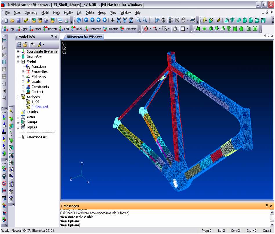
This finite element analysis (see image below) show results of stress on this bike frame, computed in NEiNastran from Noran Engineering. Source: Noran Engineering
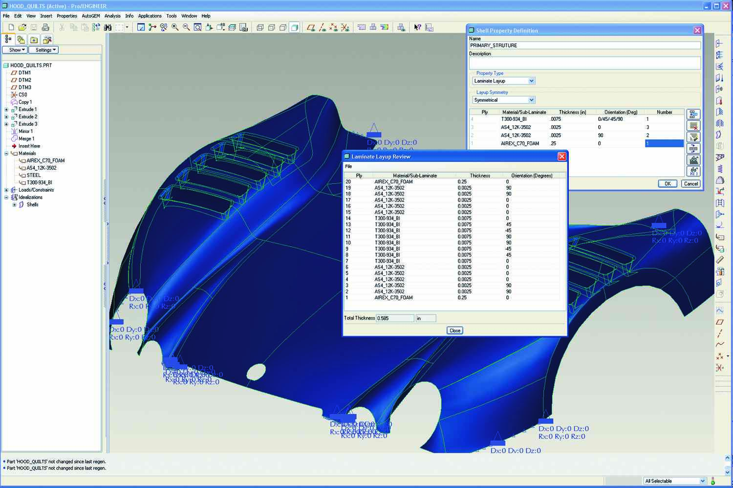
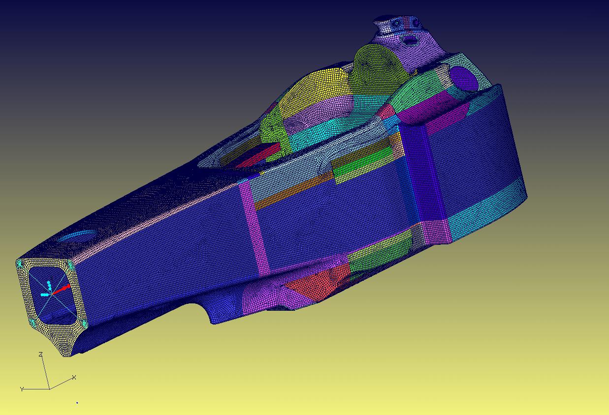
The car hood model (above) is being defined and reviewed in Pro/ENGINEER software by PTC.
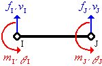
For this simple beam element, the stiffness matrix is derived from the equation pictured below.
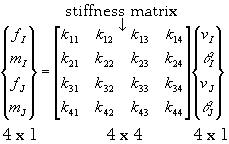
This stiffness matrix was developed from the equation (above) for a simple beam element.
Source: Noran Engineering

The NEiNastran screen shot below shows the results of finite element analysis for stress on a chassis component for this Formula 1 racer built for the Minardi Racing team. Source: Noran Engineering
Source: Noran Engineering

The displacements of this composite car hood as it is subjected to pressure loading are shown in the FEA screen shot below. Source: PTC

This equation generates the values for the stiffness matrix (displayed below) that describes the beam element (displayed above).
The product design process has traditionally involved the fabrication of test coupons, prototypes and often lengthy testing regimes. If the part under consideration is simple, with only a few options in terms of materials and relatively modest performance requirements, then trial-and-error testing of prototypes may require only a few break/learn/iterate steps to yield a saleable product. For a product of any complexity, however, prototyping and testing can significantly prolong product development and consume valuable resources.
A virtual test method
Finite element analysis (FEA) is a tool that enables design engineers to apply various types of loads to a structure and see how it will respond before going to the time and expense of constructing a prototype, explains Dennis Sieminski, who handles marketing and international sales for FEA software publisher Noran Engineering Inc. (Westminster, Calif.). FEA permits the user to construct an accurate mathematical model of the component in virtual space and then simulate the effects of a wide variety of physical tests. Dr. Paul Borgmeier of the University of Utah (Salt Lake City, Utah), a noted lecturer on FEA, explains that FEA can be used for structural testing (analysis of stress, buckling, vibration and fatigue), thermal testing (heat transfer) and fluid flow analyses as well as to determine the distribution of magnetic or electric potential. While FEA does not completely eliminate the need for physical testing (customer requirements or government regulations often, in fact, require it), the method offers users the possibility of circumventing some or all of the break/learn/iterate cycle.


FEA isn't new. The first paper on true FEA was published by Richard Courant in 1943. The method was computerized 10 years later, and the term "finite element"was first used in 1960. The aerospace industry has used FEA for many years to determine the effects of load situations on composite parts, explains John R. Tanner, launch vehicles structures lead engineer with ATK Space Systems and Sensors (Clearfield, Utah). But Sieminski points out that dramatic reductions in the cost of both hardware and software, and the development of easy-to-use graphical interfaces for the software have led to a proliferation of FEA in other fields, including automotive design, yachtbuilding, and the manufacture of golf equipment, mass transit vehicles and wind turbines.
Anywhere there is a sizable cost in prototyping, testing and quality assurance, or a compelling need to condense design cycle times and optimize part performance, FEA software is finding new users. In fact, FEA solvers are available on the Internet free of charge. However, such "share ware"programs typically have limited capabilities that make them impractical for the analysis of complex composite structures because these programs often have limited numbers of nodes and elements that can be used. Since composite materials analysis must be able to account for multilayered laminates, which may feature orthotropic and/or anisotropic materials, and the failure mechanisms associated with their properties, such as cracking, delamination and fiber failure, the model may requires a significant number of nodes and elements, explains Sieminski. In addition, high-quality FEA software should be easy to use yet provide the engineer with the power to get results that are practical and truly valuable for application to real-world problems. Specifically, the software should have features for model creation, material definition, meshing, post processing, failure criteria and data presentation that are specific to composites.
While these features don't come cheap (prices can range to tens of thousands of dollars), FEA proponents say the time and money saved by reducing the number of physical prototypes and design iterations more than compensates for the investment.
Modeling & meshing
Commercial finite element programs break the modeling process into three major steps: pre-processing, solving and post-processing. The portions of the software program that handle steps one and three (called the pre- and post-processors) act as the user interface and provide the graphical tools to construct a finite element model, that is, a geometrical representation of the prospective component. Models also can be created using a simple text file, which can allow the user to more easily make changes to the model. Mathematically, the theoretical object contains an infinite number of points along the continuum. The key to FEA is to select from among those points a manageable number of nodes (key points on the continuum) that can be connected to form element boundaries (represented graphically on the computer's monitor screen by fine lines). The result, visually, is a mesh (a pattern of elements subdivided by a grid). The function of the mesh is to break what may be a complex component into a number of elements that identify the boundaries of discrete parts over which a practical number of engineering equations can be solved using numerical techniques.
Most FE programs have a CAD-like interface for drawing this structural geometry, and many can even import CAD data directly. Meshing, the process of dividing the structure into nodes and elements, can be done automatically or manually. Automatic meshing is fast and is sometimes the only practical method for highly complex geometry, but the mesh quality is sometimes insufficient for accurate analyses. Manual meshing allows the user to specify node spacing along geometric boundaries. This can lead to better element shapes, but is more time consuming.
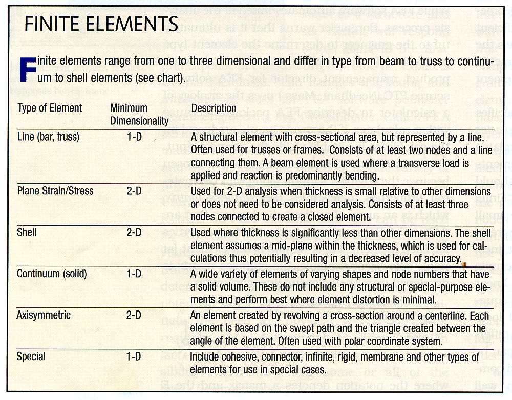
In conjunction with meshing, the user specifies element types, materials and physical properties (such as shell thicknesses). Borgmeier explains that there are many different types of elements and determining the element type and size should be the first step in the FEA process (see "Finite Elements" chart, last image, at right). Ideally, the elements are small enough that the element boundaries can be treated as if they were linear (essentially, straight lines) rather than curved. Mathematically, this permits the software to substitute a much simpler linear (or, in some cases, second order) system of equations, taking into account only the nodal locations, instead of using much more complex differential equations. In this way, calculations can be simplified even for very complexly contoured components. Assuming the mesh has been well defined, the solution for each linear element is a very close approximation of the value that would be obtained with the more complex equation required for the curve, and therefore gives the user a reasonably accurate result. Practically, it also cuts the computer processing time to a fraction of what would otherwise be required, which helps makes FEA an efficient, cost-effective tool.
The final step before solving is the application of boundary conditions (BC). In a structural analysis, BC include displacements (such as fixed or simply supported edges) and loads (such as point, line or pressure). Unlike material and physical properties, BC apply to the nodes, not the elements. The pre-processor might provide special tools for applying BC to geometric edges or faces, but the program always translates these into nodal BC.
Garbage in, garbage out
While FEA software automates much of the analysis process, Borgmeier warns that
it is ultimately up to the engineer to determine the element type best suited for
the application. John Buchowski, product management director for FEA software source
PTC (Needham, Mass.) uses the analogy of a calculator to describe FEA packages because
with a calculator, if the wrong inputs are keyed in, the calculator inevitably yields
the wrong output. It is crucial that the proper element be chosen because the engineer's
input, along with the material properties, determines the stiffness matrix, which
is an array of mathematical values that are defined by the geometric and material
properties for each element. For a simple beam element (see image #5, at right,),
for example, the stiffness matrix is developed from the following linear equation
(image #6) where the notation denotes a matrix and the
E subscript denotes elemental quantities. In expanded form, the matrix
looks like the example in image #7, at right.
The stiffness matrix relates the local forces of an element to the local displacements of the nodes that define that element, says Borgmeier. Determining the stiffness matrix is one of the processing steps that an FEA solver performs behind the scenes. In addition, it will derive the strain/displacement or stress/force relations, assemble a global stiffness matrix (a matrix for the entire part) and ultimately solve for unknowns, such as displacements which then can be used to calculate strains which are used to calculate stresses.
Sieminski warns that the user must have enough engineering experience to recognize whether or not the model's elements, together with the constraints and applied loads, provide a suitable representation of the problem at hand. Tanner also adds that once the FEA has been performed, the use of hand calculations and the engineer's prior experience can help determine if the FEA output is within reason. Dale Berry, director of industry solutions for FEA source ABAQUS Inc. (Providence, R.I.) adds that adequate training and regular use is required for effective FEA to be performed. Given that FEA training at universities and from software providers is ubiquitous, Berry adds, new users need not fear FEA.
Mapping results, predicting behavior
When the model is fully defined, it is sent to the solver. The solver calculates the system of equations for each element, and then assembles them into a global system of equations that describes the behavior of the object as a whole. Thus, when a load is applied to an FE model, load transfer is simulated from node to node along the interconnecting elements throughout the mesh. And the program, by means of the displacement function and strain/displacement or stress/force relations, can calculate that effect. The results can be represented visually on the system's monitor by the pre-/post-processor's graphics feature, typically through the use of a color scale. Results also are usually available in graph form or as raw data. In the models pictured on these pages, for instance, high stress concentrations are typically indicated in red. Based on the results, the user can refine the design by adjusting the material properties, geometry and/or boundary conditions assigned to the elements and then rerun the virtual tests - literally going through the break/learn/iterate process before the part is built.
Similarly, calculations can be run and results graphically depicted for heat transfer, electrical conductivity, sound wave absorption and a number of other effects that typically require physical testing.
FEA isn't just for testing. It can be used throughout the design process. In the preliminary phase, for example, FEA can assist engineers in making initial design decisions. To save time, Tanner illustrates, the initial shape can be modeled with simple, axisymmetric shells, which are adequate for sizing and general design overview. Since shell elements force the user to make some geometrical assumptions and accept some compromises in terms of thickness and, therefore, are inadequate for capturing through-thickness transverse shear behavior, the early element type can be changed and the composite laminate can be modeled in greater detail, layer-by-layer. Tanner explains that moving from shell models to more continuum, continuum shell, or detailed axisymmetric models as the designs progress, helps refine the discrete layers of composite materials. Moreover, orientations and material properties of specific layers can be changed without recalculating the general properties. The intent is to represent as closely as possible the actual geometry of the proposed physical structure. As the design progresses, areas of concern can be identified and submodels of these areas can be analyzed. The result is a full-on simulation of both global and local models.
Composites-specific FEA
The following software publishers are among many that offer FEA packages with integrated composites-specific features, options and add-on modules that ease the engineer's modeling task. However, it should be noted that with proper use almost any FEA package should be able to analyze composites for general conditions.
ANSYS 10.0 from ANSYS (Canonsburg, Pa.) has several composites-related additions, notes ANSYS product manager Achuth Rao. New layered solid element types help users model composite structures accurately and more easily. In addition, new cohesive zone modeling allows for the analysis of delaminations or crack propagation. While these additions are common to other FEA packages, ANSYS also has added an interface with the lay-up assist tool FiberSIM (VISTAGY Inc., Waltham, Mass.). This allows the information contained in a FiberSIM file to be input directly into an ANSYS model, permitting easy analysis of existing layups without having to create new models. Instead, the file is read into ANSYS, material properties, boundary conditions and loads are added, and analysis can begin immediately.
Noran Engineering's new NEiNastran FEA package is the latest version of its NEiNastran program developed in the 1980s from Nastran (NASA Structural Analysis Program) - one of the oldest FEA programs, it originated from a 1965 NASA project. NEiNastran, historically a standalone product, has been enhanced to assist in model creation and analysis. The most recent version of the code provides a number of benefits over earlier versions written for mainframes and amalgamated from various sources. One is the ability to more easily develop new feature and industry-specific enhancements, explains Sieminski. A new editing feature enables real-time solution monitoring, Automatic Surface Contact modeling, Advanced Failure Criteria for Composites, Stability Index Output for Sandwich Structures, a Nonlinear Tension-Only element for aircraft manufacturers, and CAD-embedded solutions.
A standalone FEA package, the latest ABAQUS product is, according to Berry, like a high-end sports car - it has very high performance characteristics but requires a skilled driver. Similar to other packages, ABAQUS offers the user several ways to interface with the program. The two most common are to use ABAQUS CAE Graphical User Interface (GUI) or to read-in an input file in text form. The GUI enables the user to import existing CAD drawings and create the mesh visually in a Windows environment. Text file input allows for easy modifications but initial file creation can be difficult. Often pre-processing software can be used to help identify errors before the file is input into the FEA package. An available add-on is an implementation of the Virtual Crack Closure Technique (VCCT), a technology developed by aerospace engineers at The Boeing Co. (Chicago, Ill.) to predict fracture and failure in laminated composite materials. Berry explains that VCCT accurately simulates delamination in composite structures, enabling the user to identify the overall load at which a crack initiates and then predict the structure's behavior as the crack propagates. It also helps users understand the stability and load-carrying capacity of the composite structure after failure - vital for assessing damage-tolerance.
FEA/CAD packages
While most FEA programs today can import data from popular CAD platforms, a new generation of FEA suites integrates solvers into CAD software. Integrated packages are available in the COSMOS component to SolidWorks, (SolidWorks, Waltham, Mass.) and the Pro/MECHANICA component of Pro/ENGINEER, from PTC. Berry notes that ABAQUS has combined its FEA program with CATIA CAD software to create its SIMULIA package. In the latter, the FEA and CAD tools may be used together, or the FEA solver can function as a standalone tool.
The pairing of CAD and FEA enables users to integrate the FE model into the part's design data. Loads and BC can be applied directly to geometry instead of nodes or elements, and meshes automatically update when the geometry is modified. Multiple FE models with different meshes, BC and solution types can be applied to the same geometry and stored with other part data.
Pro/MECHANICA operates on a different solver method where displacements are represented within each element using high-order polynomials, instead of the linear equations used in the conventional finite element method. Buchowski says this allows a single geometric element to represent a more complex state of deformation than is possible with a single, conventional finite element. This reduces the number of elements, thus decreasing computation time and solving more quickly. In addition, the same mesh can be used repeatedly, but mesh size is more difficult to control, meaning that as a design is refined it can become difficult to analyze detailed areas. Thus, many consider this type of solver to be most effective for initial design.
Buchowski adds that Pro/MECHANICA has been tailored for design analysis by minimizing the FEA-specific knowledge the user must have. However, the engineer must still have a good grasp on the engineering principles involved.
Sieminski suggests that perhaps the easiest and fastest way to get started using FEA is to model a design that has already been implemented in a product. Each FEA software vendor should be able to assist in modeling the part with their software and virtually test it in ways that replicate the physical process. This lets prospect licensees experience what is involved in model creation and establish the accuracy of the analysis based on existing results. It also gives users an appreciation for the cost, speed and quality benefits of performing these functions on a computer. Further, the exercise can help them decide whether to purchase an FEA package and training, or hire an FEA-literate consultant.


.jpg;maxWidth=300;quality=90;format=webp)


Related Content

Coriolis Composites installs AFP machine at Sabanci University
C1 robot contributes to technology development at the Integrated Manufacturing Technologies Research and Application Center (SU IMC) in Istanbul.
Read More
Automated filament winding system increases throughput, reduces manual labor for pressurized well tank production
For its new line of composite well water tanks, Amtrol worked with Roth Composite Machinery on an automated process for faster, more easily tracked production.
Read More
9T Labs, Purdue University to advance composites use in structural aerospace applications
Partnership defines new standard of accessibility to produce 3D-printed structural composite parts as easily as metal alternatives via Additive Fusion Technology, workflow tools.
Read More
TPRC training courses target thermoplastic composites
Three upcoming in-person thermoplastic composites courses, ranging from entry-level to advanced, are organized to enhance composites professionals’ knowledge in this burgeoning field.
Read MoreRead Next

CW’s 2024 Top Shops survey offers new approach to benchmarking
Respondents that complete the survey by April 30, 2024, have the chance to be recognized as an honoree.
Read More
From the CW Archives: The tale of the thermoplastic cryotank
In 2006, guest columnist Bob Hartunian related the story of his efforts two decades prior, while at McDonnell Douglas, to develop a thermoplastic composite crytank for hydrogen storage. He learned a lot of lessons.
Read More
Composites end markets: Energy (2024)
Composites are used widely in oil/gas, wind and other renewable energy applications. Despite market challenges, growth potential and innovation for composites continue.
Read More