
Additional grip types for tensile test specimens
Dr. Don Adams follows up a previous discussion of wedge grips for testing tensile specimens with a sampling of other grip types.
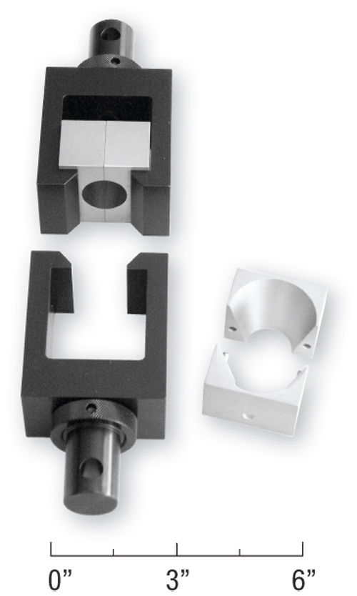
Fig. 1: Split-collet tensile grips and holders.
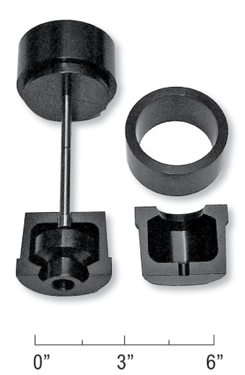
Fig. 2: Split-collet tensile grips with constraint rings
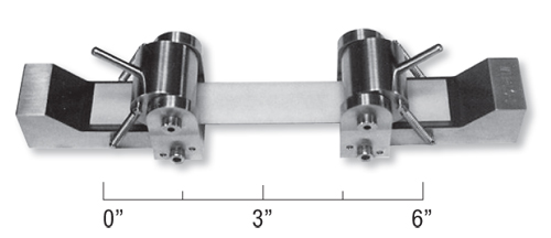
Fig. 3: Line grips.
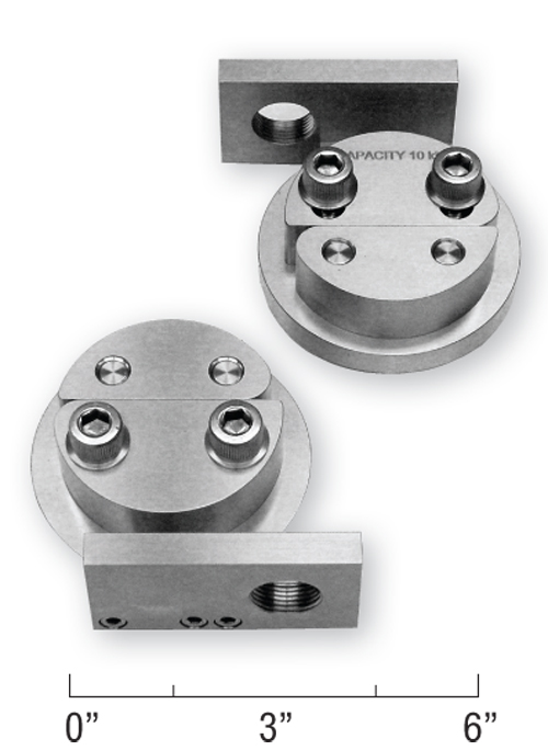
Fig. 4: Capstan grips.
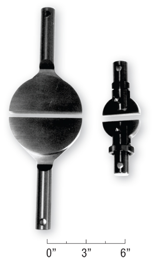
Fig. 5: Split-disk tensile grips.


When we think of tensile specimen grips, our first mental image is probably that of the wedge grips that apply uniform clamping forces to the ends of flat test specimens. These were discussed in detail in a previous column (see “Editor's Picks,” at right). But there are many other tensile grip configurations in use. A few representative types are presented here.
One example is the split-collet type shown in Fig. 1. This particular set of grips is designed for testing structural foam and similar low-strength materials. A dumbbell-shaped specimen of circular cross section is used. The split collet (collar) is shown installed in the top half of the grip fixture and separated at right. A split collet is placed around each cone-shaped end of the specimen, and then this assembly is slipped into the holders. The split collet permits uniform gripping around the full circumference of the test specimen. This particular design is limited somewhat to low-strength materials because the collet and holders can spread open under heavy loads, disrupting the load uniformity. Thus, for very strong materials, the outside diameter of the split collet often is made circular rather than rectangular, so a retainer ring can be slipped over the outside to prevent spreading. One example is shown in Fig. 2, where a button-ended specimen is installed in the upper grip, while one half of the other split collar and retaining ring is still to be placed in position around the lower end of the specimen. Often, such grips are used with both unreinforced and fiber-reinforced metals and ceramics. The surfaces of the specimen that contact the collet face must be contoured carefully to obtain uniform loading and, thus, minimize the possibility of local stress concentrations.


The same general principle can be applied to dumbbell-shaped flat (dogboned) specimens. In this case, the collet can be eliminated and the specimen simply is slipped into holders, such as those shown in Fig. 1, the ends of which would be contoured to uniformly engage the dogboned ends of the specimen.
Line grips, a quite different type, are shown in Fig. 3, with a specimen installed. Here, spring-loaded cylindrical cams wedge the ends of the flat specimen against flat surfaces. These contact surfaces can be roughened or particle-coated, if the user desires, to increase the gripping force. The grips' name comes from the fact that the curved cams makes line contact with the flat specimen rather than contacting it over a defined area as most grips do. The local stress concentrations induced in the specimen by the line contact can be reduced by inserting a thin layer of padding material at each contact surface to spread the load. Line grips are particularly useful for testing thin specimens, such as unreinforced and reinforced paper, plastic film and metal foil.
A pair of capstan grips is shown in Fig. 4. These have been used for a long time to tensile test flat tapes, rope, cable, cordage and similar linear material forms. The grips shown here are for testing flat tape. For testing other cross-sectional shapes, such as round cord, a semi-circular groove can be cut into the capstan surfaces, to help maintain the specimen cross-sectional shape as the load is applied. This may or may not be necessary, depending on the characteristics of the test material. The concept is that a long length of the material, when wrapped around a cylinder, can transmit a high tangential force to the cylinder via friction. If the specimen material will not be affected adversely by the potential abrasion, then this frictional force can be increased further by roughening the surface of the capstans (e.g., by applying a tungsten carbide particle coating). The free end of the tape is clamped between the two halves of the upper split capstan. For maximum gripping power, the tape can begin at the far right end in the split, wrap counterclockwise around the lower half of the capstan, continue around the upper half and then down onto the lower grip in the same manner. This results in a grip length of approximately one circumference plus one diameter. If less gripping power is required (for example, when testing a lower strength material), and/or to use less specimen material, the tape can start at the left end in the split and continue counterclockwise around the upper half of the capstan and then down to the lower capstan. This results in a grip length of approximately one-half the circumference plus one diameter.
If the frictional force is resisted tangentially, no net twisting moment results. Thus, the two grips are to be positioned such that the force in the specimen test section is aligned with the axis of the testing machine, as shown in Fig. 4. The load capacity of this type of grip is dictated by the diameter of the split capstans (which governs the amount of frictional force that can be developed) as well as by the strength of the grips.
Note that the characteristics of the various types of grips tend to be dictated by the material form to be tested. This is particularly true of the split-disk tensile test fixtures shown in Fig. 5. The fixture shown on the right is typical of those used to test sections of unreinforced plastic pipe. The fixture on the left was developed in the late 1950s specifically for filament-wound composites. Filament winding was a particularly prominent fabrication method at that time. A tube of the appropriate inside diameter is wound (for the standard fixture shown, the inside diameter is 146 mm/5.75 inches), and then cut into 6.4-mm/0.25-inch wide rings. With no gap between the fixture halves, the ring is slipped over the circumference of the fixture and then pulled apart in axial tension. This is a very efficient method of gripping the ring for tensile testing. One criticism of this test method is that some undesirable bending is induced in the specimen. As it stretches and thus becomes oval-shaped under load, the ring specimen at the split tends to straighten out.
Although the most important of the secondary types of tensile grips have been introduced here, there are many other types. When what appears to be a unique gripping problem is encountered, a careful literature search might reveal that a grip design already exists.


.jpg;maxWidth=300;quality=90;format=webp)


Related Content

Measuring ply-wise deformation during consolidation using embedded sensors
Strip-type shape sensor method claims real-time measurement of ply-wise deformation.
Read More
Damage tolerance testing of sandwich composites: The sandwich flexure-after-impact (FAI) test
A second new ASTM-standardized test method assesses the damage tolerance of sandwich composites under flexural loading.
Read More
Composite prepreg tack testing
A recently standardized prepreg tack test method has been developed for use in material selection, quality control and adjusting cure process parameters for automated layup processes.
Read More
Multi-scale 3D CT imaging enables digital twinning, high-fidelity simulation of composite structures
Computed tomography (CT) provides highly accurate 3D analysis of internal microstructure, performance simulation of carbon fiber/PEEK satellite strut.
Read MoreRead Next

Mechanical wedge grips for tensile testing
In tensile testing, wedge grips are used on both ends of the specimen to position the specimen in the test frame.
Read More
CW’s 2024 Top Shops survey offers new approach to benchmarking
Respondents that complete the survey by April 30, 2024, have the chance to be recognized as an honoree.
Read More
From the CW Archives: The tale of the thermoplastic cryotank
In 2006, guest columnist Bob Hartunian related the story of his efforts two decades prior, while at McDonnell Douglas, to develop a thermoplastic composite crytank for hydrogen storage. He learned a lot of lessons.
Read More