
The short beam shear test
Dr. Don Adams (Wyoming Test Fixtures Inc., Salt Lake City, Utah) discusses short beam shear testing methodology.
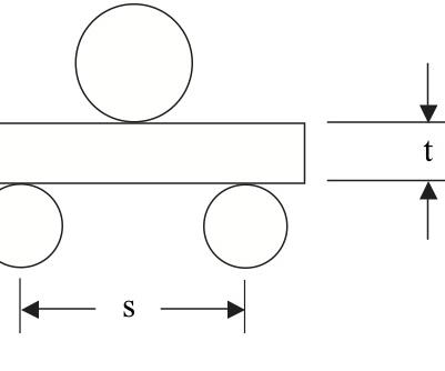
Fig. 1: ASTM D 2344 Short Beam Specimen Configuration. The loading and support cylinders are shown proportionally sized for a typical 2.5-mm/0.1-inch thick specimen and a 4:1 ratio of support span length-to-specimen thickness. Source: Don Adams
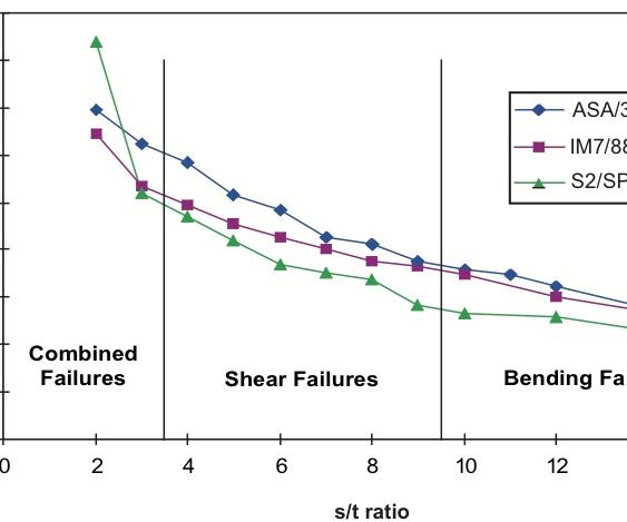
Fig. 2: Experimental Shear Strength vs. Specimen Support Span-to-Thickness Ratio (s/t) for Three Composite Materials. Source: Don Adams
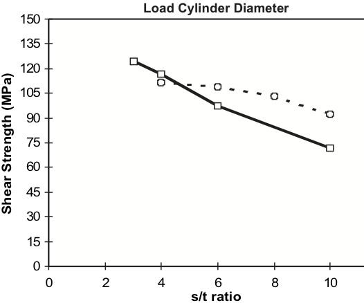
Fig. 3: Experimental Shear Strength of AS4/3501-6 Specimens for Two Loading Cylinder Diameters at Various Span-to-Thickness Ratios (s/t). Source: Don Adams


As the name implies, the Short Beam Shear test subjects a beam to bending, just as flexural testing methods do, but the beam is very short relative to its thickness. For example, ASTM D 23441 specifies a support-span-length-to-specimen-thickness ratio (s/t) of only 4:1, as sketched to scale in Fig. 1. The objective is to minimize the flexural (tensile and compressive) stresses and to maximize the induced shear stress.
In an earlier column (see "Flexure test methods" under "Editor's Picks," at right), I discussed flexure testing. In contrast to the Short Beam Shear test, flexure testing emphasizes the bending characteristics of a beam specimen, and hence high s/t ratios are used, typically at least 16:1 and often much higher. For example, ratios of 32:1, 40:1 and even 60:1 also are specified in the governing ASTM standards. These various ASTM standards for flexural testing include both three-point and four-point loadings, as discussed in detail in the previous column.


However, I concluded at that time that “three-point loading has definite advantages, particularly if the concentrated loading can be spread out a bit.” Interestingly, short beam shear testing has historically focused primarily on three-point loading. In fact, detailed studies2,3 have indicated no advantage, and perhaps even some disadvantages, in using four-point loading of a short beam.
Although the stress state in the short beam is not the pure shear that would be desired in an ideal shear test method, there are some redeeming features. Away from the loading and support points, the shear stress theoretically varies parabolically from zero on the specimen top and bottom surfaces to a maximum at the specimen mid-plane. Correspondingly, the (tensile and compressive) bending stresses are maximum on the specimen surfaces, varying linearly to zero at the midplane. These bending stresses also vary (linearly) along the length of the beam, from zero at the support points to a maximum at the loading point. That is, the (undesired) bending stresses are zero on the midplane of maximum shear stress. Unfortunately, since the beam is so short, the entire stress field throughout the beam is significantly disturbed by the local forces at the loading and support points2. Nevertheless, there is a plane of high shear stress at or near the mid-plane along the entire beam between supports, which is where the short beam typically fails.
As a result, the short beam shear test does produce reasonable values of shear strength, as was discussed in this column last fall (see "A comparison of shear test methods" under Editor's Picks"), as well as being a very attractive materials screening test. Unfortunately, the composite materials testing community often has not been very kind to this test method, and with some justification. The current edition of ASTM Standard D 2344 has even removed “shear” from the title of the standard1, calling it simply “short-beam strength,” recognizing the less than ideal stress state present.
Summarizing the above discussion, there are two primary problems: The applied loading creates high local stress concentrations, and the short length of the beam does not permit large zones of uniform shear stress. This immediately suggests two solutions: increase the support span length (s/t ratio) and better distribute the applied load.
Fig. 2 indicates the influence of s/t ratio on measured shear strength. Results for three different unidirectional composite materials are shown. The AS4/3501-6 and IM7/8551-7A are carbon/epoxy composites while S2/SP381 is a glass/epoxy composite. The trends are similar for all three materials. That is, there is a range of s/t ratios for which readily observed shear failures occur. Note that the ASTM D 2344 standard prescribed ratio of 4:1 is at the lower end of this range. At even lower ratios, what occurs is excessive local crushing of the specimen rather than shear failures. For ratios above about 9:1, bending failures begin to occur. These results suggest that an s/t ratio between 4:1 and 9:1 should be acceptable. However, note that the apparent shear strength is not constant. Lower s/t ratios produce higher values, and the higher values correspond more closely with results obtained using a more generally accepted shear test method, such as Iosipescu Shear4.
Fig. 3 indicates the influence of load cylinder diameter on the measured shear strength. The 6.4-mm/0.250-inch cylinder is the size specified in ASTM D 2344. This is compared to the results obtained using a 25.4 mm/1-inch diameter cylinder. The results shown are for AS4/3501-6 carbon/epoxy. The S2/SP381 glass/epoxy indicated similar trends. Interestingly, a Kevlar/3501-6 epoxy tested along with the other samples showed much less influence of cylinder diameter. This is not surprising since the Kevlar fiber is much softer in its diametrical direction and thus better able to blunt the stress concentrations at the loading cylinder.
What is particularly significant in Fig. 3 is that by using a larger diameter loading cylinder, which better spreads the local loading, the measured shear strength is less sensitive to variations in the s/t ratio.
The combined results in Figs. 2 and 3 suggest the conclusion that the ASTM D 2344 standard would benefit from specifying a higher s/t ratio, perhaps 7:1 rather than 4:1, and a much larger loading cylinder, namely 25.4 mm/1 inch rather than 6.4 mm/0.250 inch.
Interestingly, the three-point flexural testing I summarized at the beginning of this article also was shown, in the November column, to benefit from an increase in loading cylinder diameter. Could a message to the composite materials testing community be emerging?
Wyoming Test Fixtures Inc.
References
1ASTM Standard D 2344/D 2344M-00, “Short-Beam Strength of Polymer Matrix Composite Materials and Their Laminates,” ASTM International (W. Conshohocken, Pa.), first issued in 1965.
2Adams, D.F., and Busse, J.M., “Suggested Modifications of the Short Beam Shear Test Method,” Proceedings of the 49th International SAMPE Symposium (Long Beach, Calif.), May 2004.
3Adams, D.F., and Lewis, E.Q., “Experimental Study of Three- and Four-Point Shear Test Specimens, “Journal of Composites Technology & Research, Vol. 17, No. 4, October 1995, pp. 341-349.
4ASTM Standard D 5379/D 5379M-05, “Shear Properties of Composite Materials by the V-Notched Beam Method,” ASTM International (W. Conshohocken, Pa.), first issued in 1993.


.jpg;maxWidth=300;quality=90;format=webp)


Related Content

Notched testing of sandwich composites: The sandwich open-hole flexure test
A second new test method has been standardized by ASTM for determining notch sensitivity of sandwich composites.
Read More
Multi-scale 3D CT imaging enables digital twinning, high-fidelity simulation of composite structures
Computed tomography (CT) provides highly accurate 3D analysis of internal microstructure, performance simulation of carbon fiber/PEEK satellite strut.
Read More
Glass-coated magnetic microwires for nondestructive composites monitoring
Glass-coated, amorphous microwires combine nanometer to micrometer diameters, enabling embedding into composites without degrading mechanical properties.
Read More
Damage tolerance testing of sandwich composites: The sandwich flexure-after-impact (FAI) test
A second new ASTM-standardized test method assesses the damage tolerance of sandwich composites under flexural loading.
Read MoreRead Next

Flexure test methods
The three fundamental mechanical property characterization tests of materials are tension, compression and shear. Note that flexure is not included. This article addresses some of the reasons why. When a beam resting on supports near its ends is loaded, the supported side is in tension and the opposite side is in
Read More
A comparison of shear test methods
Dr. Don Adams compares the shear test methods that are currently available to the composite industry.
Read More
CW’s 2024 Top Shops survey offers new approach to benchmarking
Respondents that complete the survey by April 30, 2024, have the chance to be recognized as an honoree.
Read More