
Composites connect with the world of cabling
Composite cables prove they can handle high tension - on land, over water and under the sea.


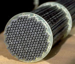
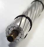
Source: EMPAA close up of a carbon composite bridge cable stay, which consists of 241 5-mm rods that will be encased in a polyethylene sheath.
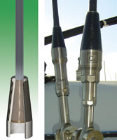
Source: Southern SparsBundles of 1-mm diameter pultruded carbon composite rods are individually pretensioned and bonded into a cone-shaped terminus plug (left) in cable terminations for sailboat standing rigging (at right).
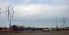
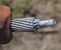
Source: Composite Technology Corp.ACCC cables installed on a National Grid line in Niagara Falls, N.Y.
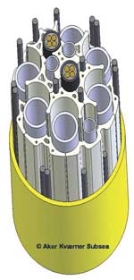
Source: DeepWater CompositesPultruded carbon composite rods stiffen umbilical lines fitted with steel tubes that carry electricity and other service from offshore platforms to subsea structures on the seabed.
Source: Composite Technology Corp.Composite Technology Corp.'s lightweight, utility-grade ACCC electrical conductor cable features a pultruded solid structural core of epoxy reinforced with carbon and glass fiber, overwrapped with conductive annealed aluminum wire.
Source: 3MThe 3M Co.'s ACCR composite-cored conductor cable features a composite core of alumina ceramic fiber (aluminum oxide, Al2O3) in a aluminum matrix, overwrapped with aluminum-zirconium (Al-Zr) wire. The composite core and overwrap both contribute to cable strength and conductivity.
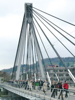
Source: EMPATwo of the cable stays pictured here on the Stork Bridge in Winterthur, Switzerland were formed from bundled carbon composite rods (see photo, p. 28), which have performed as designed for nearly a decade.
Source: EMPAAnywhere cabling is subjected to high tension and exposed to temperature change and corrosive environments, such as bridge stays, lightweight composite cable products are being developed as alternatives to traditional steel cables.
The ability to tailor the physical and mechanical properties of composite materials to suit specific purposes has made composite-for-metal replacement in structural components an attractive option in a whole range of emerging cabling markets, including composite-cored electric power transmission cables, subsea cables on offshore oil platforms, cable stays on bridges and standing rigging on racing yachts. Traditionally, cables in these markets have derived their structural strength from steel, but in the last decade, developers have prototyped and tested composite cable products for each that have demonstrated the ability to handle the high-tension loads. In fact, the most difficult technical challenge, as will become clear, has not been production of the composite cable, but rather minimizing stress concentrations where the cable is locked into end fittings or cable terminations. Moreover, cable developers maintain that composites offer greater strength-to-weight ratios, lower coefficients of thermal expansion (CTE), higher moduli of elasticity (stiffness) and/or lower electrical resistance characteristics than conventional steel components — factors that have raised significant interest among potential customers.
CONDUCTOR CABLES


Since the late 19th Century, public utility companies around the world have moved electrical power through increasingly more complex supply grids by means of transmission and distribution (T&D) cables consisting of a conductive element of aluminum wires wrapped around a core of steel wire, which bears the structural load.
Today, increasing the transmission capacity (ampacity) of a grid requires unprecedented expense. As demand for power grows, utilities must modify existing towers, to accommodate additional steel-cored cables or bear the additional load of larger-diameter, heavier cabling. Eventually, they are faced with replacing the existing towers with new, larger towers, or acquiring rights of way for additional trunk lines. The latter can be a legal nightmare in both densely populated urban/suburban areas and sparsely inhabited but environmentally regulated public lands, such as national parks, wilderness preserves and other no-build zones. Therefore, recent attempts to developed cabling with a lightweight composite core have attracted the interest of utilities.
Conventional steel cores can overheat in conditions of peak electrical demand, causing the cable to stretch and sag below acceptable ground clearance. (If cables sag too near the ground, electricity can arc, triggering a circuit breaker.) By contrast, composite-cored conductors possess a lower CTE and therefore exhibit less heat-expansion than steel-reinforced conductors. By replacing steel-cored cables with composite-cored cables, utilities can operate at higher current levels and push more power — cable makers say double the current-carrying capacity — through the system without risk of sag and disruption of service. In new construction, composites' high strength-to-weight and low sag translate to longer spans between towers, reducing the number of towers needed to carry the electrical load by 16 percent.
Opportunities for composite-cored cable span the globe, wherever there is need for increasing the capacity of the existing infrastructure — an estimated >$50 billion (USD) annual market. Currently, two suppliers offer utility-grade conductive cabling with very different composite load-bearing cores.
Composite Technology Corp.'s (CTC, Irvine, Calif.) Aluminum Conductor Composite Core (ACCC) cable is built around a pultruded carbon- and glass-reinforced epoxy core. During the pultrusion process, continuous unidirectional (0°-axis) carbon fibers supplied by Toray Carbon Fibers America (Flower Mound, Texas) or Toho Carbon Fibers Div. of Toho-Tenax (Menlo Park, Calif.) form a cylindrically shaped solid core while a layer of similarly oriented E-glass fibers, is placed around the exterior. The bundled fibers are wet out with a high-temperature toughened epoxy. CTC has not committed to a single supplier for its E-glass and epoxy resin, but currently uses boron-free E-glass from Owens Corning (Toledo, Ohio) and an epoxy from Huntsman Advanced Materials (Los Angeles, Calif.). Benton Wilcoxon, CTC's CEO, explains that the fiberglass layer serves two purposes: First, it separates the carbon from the conductive aluminum overwrap to prevent galvanic corrosion. Second, it counterbalances the more brittle carbon and improves the flexibility and toughness of the core.
The wet fiber bundle is pulled through a dedicated steel die and cured at 260°C/500°F to produce a solid, rod-shaped core in diameters from 0.190 mm/0.0075-inch to 19 mm/0.750-inch. A proprietary coating is applied and cured inline and the rod is cut to customer-specified length.
The cores are sized to fit CTC's 10 standard conductor sizes, ranging in diameter from 12.7 mm/0.50-inch to >69.85 mm/2.75-inch, which allow an ampacity range from 300 amps to >3,500 amps per line, or 200 to >2,500 kcmils (the cross-sectional area in thousands of circular mils).
Because the installed cables are subject to high tension (CTC's 9.5 mm/0.375-inch core tests to about 18,597 kg/41,000 lb at ambient temperature), cable termination posed significant questions. But Wilcoxon notes that a special fixture developed for testing the cables provided the answer. "It took a bit of innovation to grip such a small-sized core to carry a load that high during tests," he explains. The solution was a funnel-shaped epoxy test fixture, the basic geometry of which was later applied to dead-ends and splices used to terminate and connect the finished conductor in the field.
The result is an ACCC cabling system that CTC says can be operated continuously at 180°C/356°F and can take short-term "spikes" of 200°C/392°F, with only 10 percent of the sag seen in steel-cored cable. "Unlike conventional steel-core conductors, which have relatively high CTE, the ACCC conductor's core is dimensionally stable with a CTE of 1.6 x 10⁻⁶/°C (8.9 x 10⁻⁵/°F), which is comparatively much closer to the CTE of aluminum," Wilcoxon says. (Steel cable has a CTE of 11.5 x 10⁻⁶/°C.) Finished cores are overwound to CTC specifications by General Cable (Highland Hts., Ky.), using fully annealed (heat-treated and pre-stretched) trapezoid-shaped aluminum wires. Annealing, says Wilcoxon, contributes to the cable's dimensional stability.
Following several years of development and testing, eight ACCC conductors were installed for field testing in six U.S. states during the first half of 2005. Moreover, in January 2006, Utah Power put into service in Salt Lake City a 6.7-mile section of its grid recently re-cabled with ACCC conductors. CTC expects to see seven additional projects go online, from Tennessee to California, early in 2006. On January 24, CTC announced a $1.1 million (USD) order for 60 km (37.3 miles) of its cable from Jiangsu Far East Group Ltd. for installation, beginning March 15 this year, in Fujian Province, China.
Although the ACCC product costs about three times more per foot than commodity steel-cored product, Wilcoxon says, "per project, it is usually three to four times cheaper." On a multi-mile, multi-cable line, Wilcoxon explains, composite-cored cable delivers twice the power of steel for the same cable weight and tensioning. In the case of the Utah Power installation, the utility's parent company PacifiCorp.'s (Portland, Ore.) use of conventional steel-cored conductors to upgrade the line would have required replacement of the 150 towers along the route to handle the increased weight. Using ACCC cable, the utility avoided replacing all but seven of the structures, cutting material and labor for 143 towers out of the total project cost.
The 3M Co. (St. Paul, Minn.) recently entered the utility T&D market with its Aluminum Conductor Composite Reinforced (ACCR) cable. In contrast to CTC's product, 3M's features a metal-matrix composite core overwrapped with high-temperature aluminum-zirconium (Al-Zr) wires, a design in which both the composite core and the outer Al-Zr strands contribute to cable strength and and conductivity. Already a global supplier to public utilities, 3M drew on its experience with designing metal matrix composites for other demanding, high-temperature applications. The composite core consists of high-purity alumina ceramic fiber (aluminum oxide, Al2O3) in a high-purity aluminum matrix, using fibers and a metal matrix, both produced by 3M. Each core contains more than 25,000 ultrahigh-strength Al2O3 fibers. Cores range in diameter from 1.9 mm/0.073 inch to 2.9 mm/0.114-in., to fit ACCR standard sizes, which correlate to standard steel sizes, ranging from 21.84 mm/0.86 inch to 28.19 mm/1.11-inch diameters, or 477 to 795 kcmils wire size. The ceramic fibers are continuous, in 0° axial orientation and fully imbedded in the aluminum matrix. 3M's cabling is a conventional twisted cable, with an overwrap consisting of continuous Al-Zr strands manufactured using conventional stranding methods.
The outer Al-Zr strands are a temperature-resistant alloy that permits continuous operation at 210°C (410°F), with peaks up to 240°C (464°F), designed to maintain strength and resist annealing. Though appearing to be traditional aluminum, the composite core wires are nearly eight times the strength of aluminum and three times its stiffness, according to Tracy Anderson, business development manager for 3M's composite conductor program. The core is less than half the weight of a comparable steel core, possesses greater electrical conductivity, and has a CTE of 6 x 10⁻⁶/°C (3.3 x 10⁻⁶/°F) — less than half that of steel.
In contrast to CTC's ACCC cables, 3M's ACCR cables can be joined together using standard, traditional techniques, such as preformed terminations or two-part compression methods, using commercial accessories readily available from utility cable suppliers worldwide.
3M completed field-testing with installations in six states, each of which measured the response of the ACCR conductor in specific field conditions. Commercial installations include a 10-mile line for Xcel Energy (Minneapolis, Minn.). "Xcel avoided installing new towers, preserved a sensitive wetland and were impressed with the speed of implementing the composite-core solution," Anderson maintains. Pacific Gas & Electric (PG&E) installed 3M's ACCR on short line segments in the southern California city of Santa Clara. 3M has since signed agreements for a 10-mile line for Alabama Power Co. and an 80-mile line in Arizona, for Western Area Power Admin.
To compete in this conservative, well-established market, CTC and 3M point out that all testing must be thorough and complete, a task made more difficult by the lack of of established test methods. While several ASTM, IEEE, ANSI and Aluminum Assn. standards apply to utility-grade cabling, they were written for steel-cored conductors and will have to be modified to accommodate the differences in composite-cored product. For in-stance, Anderson points out that most standard tests measure the performance of overhead conductors at ~100°C/212°F, but both the 3M and the CTC conductors are designed to operate at continuous temperatures ranging between 180°C and 210°C (356°F and 410°F). Therefore, standards of manufacture for composite-cored conductors need to be established, to help convince cautious utility engineers and specifiers that they can depend on the long-term performance of this new technology.
SUBSEA CABLES
For a number of years, operators of offshore oil platforms have taken to composites in a big way above the water line, replacing corrosion prone steel with easily cost-justifiable glass-reinforced polymer piping, walkways, stairways, hand-rail, ladders, support structures and even living quarters. But composite-for-steel replacement below the water line has had an equally promising but, so far, largely unfulfilled history. Certainly there is a demonstrable need for subsea composites. As oil and gas companies in search of new reserves move drilling platforms from shallow-water wells into seas nearly two miles deep, the weight of steel has become a serious drawback. And there is little doubt that composites can best steel in a subsea setting, beginning with low weight. The high stiffness/strength-to-weight ratio of carbon composites is a key driver: a carbon composite rod typically has nearly the same stiffness as steel but only 20 percent of the weight, plus lower elongation. Moreover, carbon's near-neutral buoyancy, long-term fatigue- and corrosion-resistance and greater insulative properties make it much more suitable in an often cold and always aggressive saltwater environment. However, two major challenges have retarded development. First, offshore operators are reluctant to pay the considerably higher price for carbon fiber, even when its use is demonstrably more cost-effective. Second, they face the technical challenge posed by termination of anisotropic fiber-reinforced composite materials in standard attachment devices designed for steel and aluminum cables.
A pioneer of subsea cabling, Aker Kvaerner Subsea AS (AK Subsea, Oslo, Norway), in conjunction with Conoco Phillips (Houston, Texas), applied its years of experience making steel tube umbilicals to the development of carbon composite cables for use in place of the steel tethers that currently anchor tension leg platforms (TLPs) to the seabed. Their joint venture company, DeepWater Composites AG (Lysaker, Norway) also began to transfer that technology to the design and manufacture of carbon-stiffened, hollow umbilical cables, through which electrical, fiber-optic sensing and other service lines connect topside and subsea operational structures. After the development phase, AK Subsea bought ConocoPhillips' share of DeepWater Composites, and is now the sole owner, according to Turid Storhaug, department manager of the DeepWater Composites group.
Storhaug explains that the carbon rods for AK Subsea umbilicals are stiffening members in a complex of steel tubes that will carry electricity and chemical service to the subsea structures. The rods and tubes fit into a tailored PVC profile, which separates the carbon from the steel. The entire assembly is encased in a polyethylene sleeve. A typical cross-section is shown in the diagram on p. 26.
"The carbon rods have the same lay angle as the other elements in the umbilical," says Storhaug. (Lay angle is the degree of helical twist in the individual cable elements that enables the umbilical to be spooled onto a reel.) "The small internal lay angle of about 2°, which is typical for the AK Subsea umbilical, is important to ensure the direct action of the carbon rods, as they come into action simultaneously with the steel tubing," she explains.
The carbon rods are pultruded by Vello Nordic AS (Skodje, Norway), using Zoltek Inc. (St. Louis, Mo.) Panex 35 tow in a DION Impat 9100 vinyl ester matrix, supplied by Reichhold (Research Triangle Park, N.C.). Vello will supply 384 carbon rods, each automatically cut to 3,050m/10,007-ft length. They will be wound on 1.8m/6-ft diameter reels and delivered to AK Subsea's facility in Mobile, Ala. to be assembled into four umbilicals destined for the Merganser platform, operated by Kerr-McGee Corp. (Oklahoma City, Okla.), and the Mississippi Canyon MC-902 platform, run through a consortium of five independent operators. Both are exploring deepwater reserves at a depth of about 3,000m/9,800 ft in the Gulf of Mexico.
According to Storhaug, however, widespread commercialization of composite tethers and composite-reinforced umbilicals is still on hold. "We have done a lot of testing and qualification but, because of the fiber shortage, I don't think it's realistic to look at our TLP installation with carbon fiber tethers in the next one to two years," says Storhaug. Beyond concern for carbon's availability, she sees a need for more progress in the nondestructive testing and in-line inspection of pultruded parts, However, she adds that AK Subsea is participating in studies and many oil companies are interested in the tether technology. She stresses that, overall, Aker Kvaerner is enthusiastic about carbon composites and the potential of its carbon-stiffened umbilicals. "I think the technology has come to stay," she says.
BRIDGE CABLE-STAYS
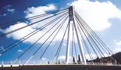
Composites also are beginning to find a place in cable-stayed bridges. As the name implies, this type of bridge supports its deck/girder system by means of a series of cables attached at regular intervals to the girder and strung diagonally to attachment points on one or more vertical supports (as in the photo on p. 24). Like utility-grade power transmission cabling, bridge cables must resist sag under dead load, and cable-stay systems also must be able to withstand complex wind loads, changes in temperature and earthquake tremors. For these reasons, cable stays traditionally have been steel, but composite cables have been installed on two cable-stayed bridges for more than a decade, where builders expect them to demonstrate that their long-term durability, corrosion resistance and resulting low need for maintenance will offset greater upfront cost.
The first bridge to feature an alternative to steel stays was probably the Aberfeldy footbridge, which links two sections of a public golf course that straddles the River Tay in Scotland. Linear Composites (Keighley, W. Yorkshire, U.K.) provided the PARAFIL cable array that supports the 63m/207-ft main span. PARAFIL consists of a core of parallel, closely packed, dry Kevlar fibers encased in a polyethylene sheath. While not a composite cable this was probably the first use of fibrous materials on a cable-stayed bridge.
The first composite cable stays were probably those on a pedestrian bridge constructed by Freyssinet International (Velizy, France) over the Gave de Pau river in Laroin, France. Sixteen carbon composite cables supporting the 100m/328-ft main span (standard steel cables were used for the back stays — cables connecting the tops of towers to anchors based on land). The 6-mm/0.236-inch diameter cables — in lengths ranging from 20m to 45m (65.6 ft to 147.6 ft) — were assembled on site, using carbon fiber rods pultruded at nearby Soficar SA (Saint-Maurice, Cedex, France), using Torayca carbon fibers. The rods were delivered on a reel, cut to length and bundled in groups of seven within a high-density polyethylene (HDPE) sheath. Freyssinet was able to use an anchorage very similar to its standard steel-stay termination, but inserted a layer of petroleum wax to provide a cushion between the composite cable and the anchor jaw, to protect the composite from damage.
Completed in 1996, the Stork bridge in Winterthur, Switzerland, is said to be the first cable-stayed vehicular bridge with composite cables: two of its 24 stays are carbon composite, installed to demonstrate their use and long-term behavior in this application. The remaining stays are traditional steel. The Stork deck spans a river and a railroad station. A central A-frame tower supports two spans: one 63m (207 ft) and the other 61m (200 ft). The composite cable project was proposed and supported by Prof. Dr. Urs Meier, deputy director general of the Swiss Federal Laboratories for Materials Testing and Research (EMPA, in Dubendorf, Switzerland).
Each composite stay cable consists of a bundle of 241 carbon epoxy wires, 5 mm/0.2 inch in diameter, pultruded by Stesalit AG (Zullwil, Switzerland) using standard-modulus T700S carbon fiber from Toray Industries (Tokyo, Japan). The wires have a fiber volume of 65 to 70 percent and tested tensile modulus of 165 GPa (24,000,000 psi) with tensile strength of 3,300 MPa (478,000 psi).
Each cables is assembled from 241 parallel wires, which are sheathed with HDPE casings. The HDPE is filled with carbon black as UV protection.
Meier says that a full-scale, prototype cable, designed to bear a 12 MN/1,200-ton load was subjected to a load "three times greater than the permissible load of the Stork Bridge for more than 10 million load cycles," with no damage. EMPA equipped the composite cables, their anchorage and the neighboring steel cables with both conventional and state-of-the-art fiber-optic sensors to monitor for any stress or deformation. "The results after nine years of operation are fully satisfactory," Meier says.
The assembled cables were terminated in a box anchorage at the apex of the A-frame towers by BBR Systems (Schwerzenbach, Switzerland) using a technique patented by Meier and two Swiss colleagues, assigned to EMPA and licensed to BBR. Each cable is anchored into a molded epoxy cone within a conical steel shell casing, with the boundary surface between the anchor cone and the casing designed to allow free sliding. The modulus of the epoxy cone anchorage is graduated from soft, at the cable entry area, to stiff at the anchor terminus, to provide uniform shear force transfer to the transverse pressure-sensitive carbon fiber-reinforced polymer (CFRP) rods. The cables were installed following essentially the same procedure used for the steel cable stays.
Meier emphasizes that technology for carbon composite cables is "already on a very high level" but laments that bridge developers still tend to focus on CFRP's upfront cost rather than life-cycle cost and classify them as "too expensive."
YACHT RIGGING
For some time, boatbuilders who specialize in top-end racing and performance yachts have replaced traditional wood and metal components — and even traditional sail fabrics — with composites (see sister magazine High-Performance Composites' September 2005, p. 44). The latest evolution is composite-for-metal replacement in the standing rigging that holds the mast upright and secures it to the deck.
The primary motivation is weight reduction. For every 0.45 kg/1 lb of weight removed at the top of the mast of a typical racing yacht, about 3.6 kg/8 lb of ballast can be removed from the keel. Since less ballast is needed — several tons less, in some cases — structural strength requirements elsewhere can be reduced. This minimizes overall material cost and makes the vessel faster and more responsive without loss of stability.
Composite cabling manufactured with carbon, aramid and polybenzoxazole (PBO) fibers, such as Zylon (Toyobo, Osaka, Japan), typically save some 60 to 75 percent of the weight compared to the steel rigging they replace, without sacrificing strength. The breaking strength of composite rigging is significantly higher than Nitronic 50 stainless steel, considered state-of-the-art for steel rigging. While the modulus of elasticity (elongation) of the fibers varies, the potential for elongation greater than that of steel can be countered by increasing the cross-sectional area of the composite rigging.
Southern Spars (Auckland, New Zealand) produces its Element C6 carbon cables for new and retrofit rigging at its U.S.-based Rhode Island Composite Rigging division (North Kingston, R.I.). Based on technology originally developed by Air Logistics Corp. (AirLog, Pasadena, Calif.), an Element C6 cable consists of bundles of 1-mm/0.039-inch diameter rods. The rods are individually pultruded using a single tow of 12K T-800 intermediate-modulus carbon fiber from Toray Carbon Fibers America and AirLog's ALC 320-3 epoxy resin. Each rod represents about 227 kg/500 lb of tensile strength, and cables can be customized for specific performance requirements. "The rods are about 50 percent stronger than Nitronic 50 stainless steel, at a fraction of the density," says Southern Spars' vice president Scott Vogel. Thirty-four rods are bundled for a 6.35 mm/0.25 inch cable. This cable has a breaking strength of 5,715 kg/12,600 lb and an ultimate stress capability of 2,551 MPa/370,000 psi. The bundles are encased in a protective jacket of carbon or aramid braid from A&P Technology (Cincinnati, Ohio).
Air Log faced a significant termination challenge presented by shock loads imposed on the already highly tensioned rigging in high winds and rough seas. A patented, truncated cone design takes advantage of wedge mechanics to increase terminus holding power as the wind creates tensile stresses on the rigging — preventing what, early on, was a recurring problem with composite rigging pulling out of end fittings and failing spectacularly. Cable rod ends are adhesive-bonded to each other and to the inside of a hollow, cone-shaped terminus plug made from carbon/epoxy prepreg, with its wider end at the cable's end. The titanium terminal fitting's inside geometry conforms exactly to the plug's outside geometry. As tension on the cable increases, the compression load of the terminus on the plug increases as well, gripping the rods more firmly, but distributing the compressive force evenly over the full length of the rod bundle to avoid damage.
Element C6 has performed without incident on six top racing yachts, including the 27.4-m/90-ft Genuine Risk racing sloop (rigged in April 2004). The latest conversion is the Wally 94 Y3K racing yacht (April 2005), a recent winner in the May 2005 Palma Regatta on the Mediterranean.
Elsewhere, Custom Composite Rigging LLC (CCR, Plantation, Fla.) was formed to sell carbon composite rigging patented by naval architect Georg Thomas for the sailing yacht market. CCR's rigging consists of an assembly of parallel nested hexagonal tension rods. The rods are pultruded to CCR specifications by various manufacturers, using high-performance carbon fiber and epoxy resin, with fiber volume between 60 and 70 percent. A typical assembly comprises a center rod from 3 mm to about 7 mm (0.118 inch to about 0.275 inch), surrounded by six same-size rods. Epoxy adhesive is used to bond the exterior rods to the to the facets of the center rod. This rod assembly is then pultruded as a unit through a larger hexagonal die, where additional carbon fiber and epoxy resin fills the spaces between the exterior rods to create a single hexagonal cable. Unidirectional carbon or PBO fiber is laminated over the formed cable.
If the customer requires greater torsional strength and protection against chafing, then a carbon fiber or Kevlar (aramid) fiber braid from A&P Technology can be pulled over the cable and impregnated using rubber-toughened epoxy, Thomas says.
End terminals are stainless steel or titanium shanks passivated (chemically treated or coated) to avoid corrosion between the metal and carbon. The shank sleeve and cable have complementary dual tapering along their lengths, a patented feature designed to eliminate stress concentrations at the load transfer joint.
Thomas says CCR currently has about 20 cables in service on Hall Spars' yacht Samba and Thomas' own sailing catamaran.
PLANNING TO PERSEVERE
While the foregoing represent promising cabling solutions that, for the most part, are ready for commercialization in their respective markets, high interest in the technologies thus far has been difficult to convert to lucrative sales. Each technology faces hurdles imposed not by questions about its technical viability, but rather about fiber availability, lack of standards and testing/inspection methodologies and/or the customer's traditional adherence to the tried and true over anything new.
But with products in the field — some for more than a decade — cable developers now have the means to demonstrate their long-term durability, corrosion resistance and resulting low need for maintenance, which they are confident will overcome, eventually, remaining concerns about quality and upfront cost. In the world of high-tension cabling, composites' success is no longer a matter of debate, it's just a matter of time.


.jpg;maxWidth=300;quality=90;format=webp)


Related Content

Materials & Processes: Fabrication methods
There are numerous methods for fabricating composite components. Selection of a method for a particular part, therefore, will depend on the materials, the part design and end-use or application. Here's a guide to selection.
Read More
Large-format 3D printing enables toolless, rapid production for AUVs
Dive Technologies started by 3D printing prototypes of its composite autonomous underwater vehicles, but AM became the solution for customizable, toolless production.
Read More
PEEK vs. PEKK vs. PAEK and continuous compression molding
Suppliers of thermoplastics and carbon fiber chime in regarding PEEK vs. PEKK, and now PAEK, as well as in-situ consolidation — the supply chain for thermoplastic tape composites continues to evolve.
Read More
Carbon fiber in pressure vessels for hydrogen
The emerging H2 economy drives tank development for aircraft, ships and gas transport.
Read MoreRead Next

CW’s 2024 Top Shops survey offers new approach to benchmarking
Respondents that complete the survey by April 30, 2024, have the chance to be recognized as an honoree.
Read More
From the CW Archives: The tale of the thermoplastic cryotank
In 2006, guest columnist Bob Hartunian related the story of his efforts two decades prior, while at McDonnell Douglas, to develop a thermoplastic composite crytank for hydrogen storage. He learned a lot of lessons.
Read More
Composites end markets: Energy (2024)
Composites are used widely in oil/gas, wind and other renewable energy applications. Despite market challenges, growth potential and innovation for composites continue.
Read More