
3D Printing Moves Into Tooling Components
Some pundits predict that 3D printing, or additive manufacturing (AM), will change our world forever. While that may yet be, one thing is clear: The growth of 3D printing over the past two decades has wrought significant change in composites tooling. Although AM’s most obvious advantage is direct part production without tooling, the growing trend in the aerospace and automotive sectors at present is its use for fast, on-demand builds of mold tools to keep pace with accelerating composite part design cycles and demand for faster overall part processing speeds.

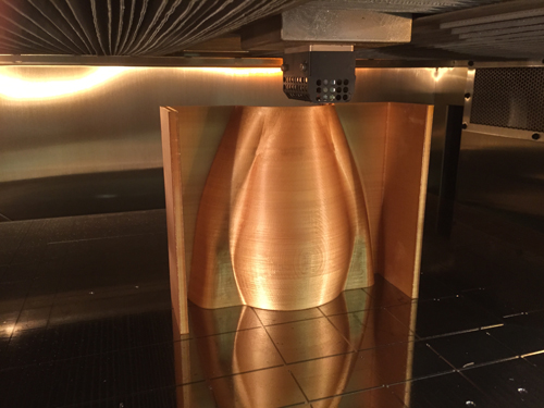
A 3D printed tool made with a new, high-temperature-capable polymer, Ultem 1010 from SABIC (Pittsfield, MA, US), is shown in the build chamber of a Stratasys (Eden Prairie, MN, US) printing machine. Ultem’s properties make it useful as layup tooling. Source | Stratasys
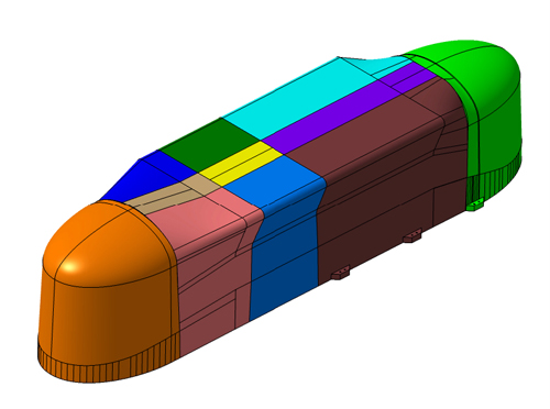
This CAD drawing from Aurora Flight Sciences (Manassas, VA, US) shows a multi-piece printed male mandrel for an aircraft belly fairing, as assembled for layup of the part. A male tool design can help to mitigate issues with tool growth when heated. The ease of assembly, via either welding or adhesive bonding of the printed thermoplastic, mitigates the 3D printing machines’ current size limitations. Source | Aurora Flight Sciences
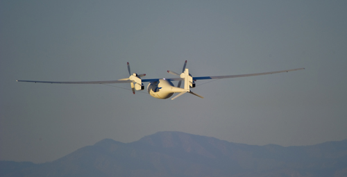
The Boeing Co.’s (Chicago, IL, US) John Melillo reports that low-cost AM tooling reduced development cost for Boeing’s Phantom Eye UAV. Mnay of it’s parts were made on 3D-printed tooling, including the huge wingskins for its 46m wingspan. Source | The Boeing Co.
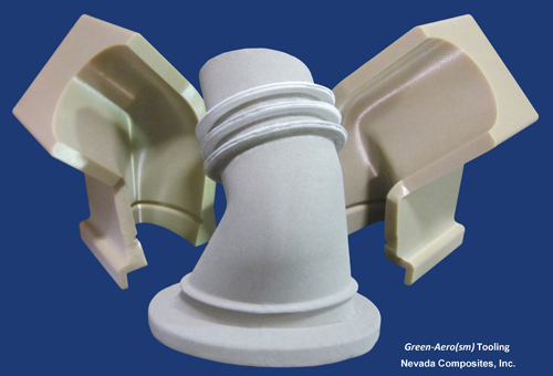
Nevada Composites (Dayton, NV, US), a producer of washout tooling mandrels, uses FDM printed tooling to mold its water-soluble products. Source | Nevada Composites
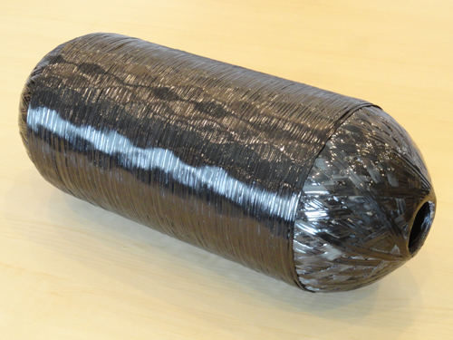
ExOne (North Huntingdon, PA, US) says this test mandrel was printed in a pressure vessel shape, using fine foundry sand mixed with a water-soluble binder. The binder system remains water soluble at temperatures up to 190°C, sufficient for most composites processes. Source | ExOne


Some pundits predict that 3D printing, or additive manufacturing (AM), will change our world forever. While that may yet be, one thing is clear: The growth of 3D printing over the past two decades has wrought significant change in composites tooling. CompositesWorld's (CW) recent coverage of AM parts acknowledged 3D printing as a source of tooling as well, but the broad scope of the AM tooling trend justified a more thorough examination.
Although AM’s most obvious advantage is direct part production without tooling, the growing trend in the aerospace and automotive sectors at present is its use for fast, on-demand builds of mold tools to keep pace with accelerating composite part design cycles and demand for faster overall part processing speeds.


One tooling expert recently confided to CW, “We’ve been looking at this for years, but now the technologies are getting better,” citing the availability of faster, larger and less-expensive AM machines and higher-temperature materials that address some previous issues with rapid moldmaking.
“We’re seeing some really good fits for additive manufacturing in composites tooling,” confirms project engineer Dan Cottrell at Aurora Flight Sciences (Manassas, VA, US). But the key is that AM now enables its users to circumvent much of the lead time — the wait time — and eliminate many of the multiple toolmaking steps that stand between the molder and the beginning of his first part production-and-assembly cycle. “Metal tools take months,” Cottrell points out. “AM tools take days … or hours.”
Challenges, and benefits
The focus here is on polymeric tooling (3D printing of metal tooling is a growing trend as well), and the sources interviewed for this article use fused deposition modeling (FDM) processes for 3D-printed tooling applications, at least at present. FDM is currently the most mature and widely used AM method. Given those parameters, the use of AM for aerospace tooling can be broken down into three broad areas:
- Rapidly-produced master models, from which a part splash or reverse is made with more traditional composite materials
- Actual layup tools used to produce composite parts, either for autoclave or out-of-autoclave processes
- Washout mandrels for trapped tooling.
A fourth category — ancillary holding fixtures, jigs, trim tools, or metal forming dies — is expanding as well.
AM for tooling still presents some challenges. For one, printer working size is limited, but sources agree that envelope restrictions do not limit tool size because a large tool or jig can be printed in segments and joined using thermal welding or structural adhesive bonding methods.
Another challenge is that the use of 3D printing is what Mike Vander Wel, head of equipment and tool engineering for Boeing Commercial Airplanes (Seattle, WA, US), refers to as “application dependent.” Low-temperature, short-run tools for prototyping that won’t see high temperatures, for example, are commonly 3D-printed and well within AM’s scope. But tools that must withstand the heat of a cure cycle in an autoclave? These, he says, are more formidable. “But our application envelope is expanding,” he adds, because new materials may expand that space.
Heat is problematic, in part, because AM materials are (usually) unreinforced plastic polymers. They expand if heated, and it can be tough to maintain dimensional stability as mold size increases, explains Tim Schniepp, project manager and additive manufacturing research engineer with extensive aerospace experience at Stratasys Inc. (Eden Prairie, MN, US). “Coefficient of thermal expansion [CTE] is certainly a challenge, but there are ways to address or compensate for that,” he says. Schniepp and Stratasys application engineer David Dahl recommend recently introduced Ultem 1010, a polyetherimide (PEI) polymer from SABIC Innovative Plastics (Pittsfield, MA, US) with a CTE about twice that of aluminum. Of all the materials available, to date, for FDM 3D printing, Ultem 1010 reportedly has the lowest CTE, and a Tg of 217°C. Another way for dealing with CTE is to avoid female tool designs if possible, which can lock the part in the mold, and instead opt for mandrel, or male, approaches, where higher CTE can be used to advantage to provide consolidation pressure.
Challenges also include surface finish and tool porosity. “The way FDM works and lays down layers, yes, it creates some roughness on the surface, and there is going to be porosity,” says Schniepp. Again, he and Dahl say it is not insurmountable. With some hand sanding — they point out that sanding is normally done in any case to finish tools made with composite materials — an acceptably smooth surface finish can be achieved. To deal with AM tool porosity, Schniepp recommends “envelope” vacuum bagging, which completely encloses the part and the tool, negating the effects of potential porosity.
Schniepp also recommends the use of a good sealer, and Stratasys is working with Airtech International Inc. (Huntington Beach, CA, US), investigating ToolTec CS5, a Boeing-approved contact film material, and Toolwright-5 adhesive-backed film, both of which reportedly work well on relatively flat tools to eliminate porosity. The company also is looking at two-part liquid epoxy sealers, including Hysol EA-9394 from Henkel AG & Co. KGaA (Bay Point, CA, US) and BJB TC-1614 from BJB Enterprises Inc. (Tustin, CA, US), which are easier to apply on more complex tool shapes. “In general,” adds Schniepp, “the best sealer method is geometry-dependent and our plan is to provide guidance in our upcoming design duide.”
The guide is a work in progress, led by Dahl, who with Schneipp works within the Vertical Solutions business unit at Stratasys, which provides actual application support for customers. (Stratasys also fulfills customer tool orders through its Stratasys Direct Manufacturing service bureau.) Says Dahl, “There is so much demand now, and so much interest in this technology for tooling, we believed the design guide was warranted.” Scheduled for release in early 2016, it will give concrete advice to customers using AM for tooling production.
Aurora Flight Sciences, for one, is an active and enthusiastic customer/partner with the Vertical Solutions group, because, Cottrell says, “we’ve got a lot of actual experience, now, making parts on these tools.”
A viable alternative to traditional tools
Limitations and challenges notwithstanding, AM tooling is earning a place in the aerospace composites toolbox. Cottrell has worked with Stratasys on the design and build of 24 tools, so far, for parts flying on low-volume UAVs as well as for commercial aircraft customers. One example, currently in process, is a 2.8m long by 0.6m wide by 0.6m deep tool, made with polycarbonate, for a belly pod fairing. Rather than produce a female tool, relates Cottrell, the Aurora Flight Sciences/Stratasys team designed a male mandrel, divided into seven segments. When the segments are joined, and it and the pod layup are bagged against a large plate, the arrangement will allow the plies to move and grow slightly with the tool against the vacuum bag during cure — the male tool geometry will provide some compaction, without the worry that the laminate will restrict tool growth, or that the tool will break fibers.
“We had worked with Stratasys to test some printed coupons made from layups on both male and female geometries. The coupons from the male layups produced well-consolidated laminates,” he explains. “We’re not very strict on the finish of the outer mold line [OML] for this part, so the male mandrel approach will work well.”
“AM tool structure can be optimized to any degree you want, because the print file can be easily modified,” asserts Dahl. An optimized tool, he explains, can be made thicker in some areas, and thinner in others, and the internal support build structure can be modified by varying the print raster paths and internal support density. These techniques provide strength and rigidity where needed, and can minimize tool expansion and movement, depending on the part processing methods.
Most telling is how tooling lead time can be compressed. Cottrell explains that a typical aluminum or composite production tool takes about two months to design, produce, finish and ship, contrasted with the seven days required for an AM tool of similar size. The tool cost per cubic centimeter is less than half that of a metal or traditional composite version, minus the cost of the printing machine. “And this is for a solid tool,” Cottrell points out. “We could make it for even less, using less polymer material, if it were better-optimized.”
Aurora Flight Sciences is involved in several proprietary programs with major OEMs that involve printed tools. “One of the beauties of this technology,” says Cottirell, “is we can test, iterate the design, incorporate lessons learned into the final tool design and still have it done within days.”
OEMs at the forefront
Boeing and Airbus are following this trend, closely. Boeing was an early adopter, and began 3D printing as early as the 1980s, says Mike Vander Wel, head of equipment and tool engineering for Boeing Commercial Airplanes: “We were pushing the envelope back then. In the past few years we’ve been looking harder at this, and integrating it into our operations more systematically.” Vander Wel notes that it has been an “evolutionary, not a revolutionary” journey, and says, “It is absolutely viable as a technology, for both parts and tools.” He cites three factors for Boeing’s increasing adoption of the technology: the cost of printing itself has dropped, material cost has also decreased and the degree of innovation is changing radically, resulting in continuous improvements.
Vander Wel points out that AM’d tooling enables the company to accelerate design cycles: “In the past, it was long lead times to get parts and tooling to the factory floor, but with this technology we can turn around design concepts much faster.” The cultural change has been encouraged by the fact that Boeing has made industrial 3D printing machines — mostly Stratasys Fortus 400 and 900 systems — directly available to engineers right at its manufacturing sites, to encourage experimentation and use. Further, Boeing has partnered, since 2005, with the Lotus Formula 1 auto racing team to test and incorporate 3D printing technologies into its extremely fast vehicle development cycles — cycles that the aircraft OEM can’t match. That partnership led to a Boeing patent on the use of chopped and milled recycled carbon fiber (from its composites fabrication waste) to create stronger printed parts, reportedly with isotropic distribution of short fibers.
Vander Well credits AM tools with helping ot keep costs low and schedules in line for the company’s high-altitude, long-endurance (HALE) Phantom Eye, and newer Phantom Swift vertical-takeoff-and-landing (VTOL) prototype UAVs (see “Learn More”) developed by Boeing Phantom Works. Nick Melillo, of Boeing R&D, spoke in 2013 at the SAMPE Europe conference in Paris about the use of low-cost AM tooling and how it reduced Phantom Eye development cost, without adversely affecting the vehicle’s design. The prototype Phantom Eye has a 46m wingspan, and its huge wingskins were made with out-of-autoclave-capable prepregs layed up on AM tooling, as were many other of the aircraft’s structural parts. Said Melillo, “3D printing for tooling and parts is going gangbusters.”
The right tools for aircraft repair
AM is significantly useful in aircraft repair and maintenance — Cottrell notes that AM technology has become invaluable for repair of legacy aircraft for which OEM spares are no longer available. The U.S. Department of Defense (DoD), for example, operates several repair depots around the US, and elsewhere in the world, to keep aging defense aircraft flying. The Fleet Readiness Centers (FRC) of the US Naval Air Systems Command (NAVAIR) use AM tooling to mint spare parts that are otherwise hard to come by or are simply no longer available, says Robert “Yogi” Kestler, Science & Technology (S&T) lead at FRC East located at Cherry Point, NC, US. FRC East is the maintenance, repair and overhaul center for all US Navy and Marine Corps vertical-lift aircraft. “Composites are a big part of what we do, day to day, and it’s growing as older, metal-centric aircraft are retired,” adds Robert Thompson, a materials engineer at Cherry Point.
Douglas Greenwood, an aerospace engineer at the center, says that a typical legacy composite repair project used to require manual methods to capture part geometry, replicating those part features with a low-temperature fiberglass splash, then making a reverse mold followed by a production tool for part layup. But, AM and digital tools are transforming that process. Today, a 3D scan captures part surfaces, either with a contact device like a FARO Technologies (FARO, Lake Mary, FL, US) or noncontact laser scanning, and the scanned data are converted into a solid CAD model. From there, the data can be fed to a 3D printer to quickly make the tooling for a replacement part.
Greenwood and Thompson say the group obtained its first 3D printer in 2006, and began to investigate making parts for “fit and form” applications, that is, validating CAD file information to ensure a part would fit properly, before undertaking conventional CNC machining and/or mold production. Later, in 2010, the group began more serious experiments, including direct 3D-printed tooling. Across the three industrial FRC installations, NAVAIR operates nine 3D printers, employing FDM and three other types: jetted binder, stereolithography (SLA) and selective laser sintering (SLS) technologies. Says Kestler, “Our AM efforts for composite tooling are still in their infancy, right now, but we’re very interested in moving forward.”
Greenwood echoes previously noted concerns about managing CTE issues and finding AM materials able to withstand autoclave conditions. Given that, FRC East currently prefers the approach of using AM to print a master pattern with FDM polycarbonate, then using it to make a carbon/epoxy mold. But the group also is working with industry on composite tools, using filled photopolymer resins that might be able to withstand high-temperature, high-pressure conditions.
Printing trapped tooling
Trapped tooling, sometimes called “lost-core” tooling, refers to a shape or mandrel around which a part is constructed that is subsequently removed after cure. Removable mandrels have been in use since the beginning of composites manufacturing. Trapped tooling materials vary widely. They can be made from inflatable bladders, complex extractable (collapsible) metal mandrels, breakable cores of eutectic salts, ceramic, foam, plaster or urethane, and so-called “washout” tooling, made of soluble material that can be dissolved or melted and removed. At least three suppliers are using AM to rapidly print, rather than laboriously mold, water-soluble trapped mandrels to fit any complex shape. Stratasys is one.
Advanced Ceramics Manufacturing (ACG, Tucson, AZ, US) offers a product called RapidCore, a 3D printed material that reportedly withstands autoclave pressure and temperature (see “Learn More”), which has been adopted by Boeing, Airbus and other OEMs. Although Nevada Composites (Dayton, NV, US) is not using AM to directly produce its Green-Aero washout mandrels, it is printing ABS with FDM methods to produce the complex tools within which its washout mandrel material is molded.
Founded in 2005, ExOne (North Huntingdon, PA, US) is a publicly traded technology company that provides both 3D printing machines and 3D printed products. ExOne has worked for years printing sand particles to make casting molds and cores for metal parts, but now offers 3D-printed water-washout tooling for composites manufacturing. Jessie Blacker, ExOne’s product development manager, says, “Our printed cores can be produced quickly and then simply washed out of a part after cure.” For low-volume manufacturing or proofing, ExOne can print tool bodies that, after coating, can last for short runs of parts under most processing conditions.
Blacker describes a test mandrel printed in a pressure vessel shape, using fine foundry sand mixed with a water-soluble binder. The binder system remains water soluble at temperatures up to 190°C, sufficient for most composites processes. “We offer a silicate binder if temperatures need to go higher,” he says. He also explains that mandrel CTE can be modified to customer specs by varying the base sand material — for example, metal powders, carbon, zircon or ceramic can be added — to achieve a CTE almost equal to that of carbon fiber, to match tool and part.
The test mandrel was coated with a solution based on the same binder system, but at a higher concentration, then hand-sanded and sprayed with a PVA mold release. The mandrel then was filament-wound with a carbon fiber towpreg overwrap and oven cured at 135°C for two hours. After cure, it was not only possible to wash away the mandrel with water but also to completely recover all the sand after the binder dissolves, reports Blacker, which then can be reused: “The material is compatible with all resin systems, with the exception of phenolics, which give off moisture during cure, and can withstand autoclave pressures.”
In addition to washout tooling, ExOne also prints prototype, master pattern and standalone layup tools, in a variety of sand and fine-grained metal materials with tailorable CTE, to match process needs. “For layup tools or master patterns, we would recommend using one of our nonsoluble binders,” adds Blacker. The company is starting to make inroads: aerospace fabricator San Diego Composites (San Diego, CA, US) is using ExOne material as a washout tool to manufacture a complex part for a proprietary customer.
The only direction is up
Boeing’s Vander Wel stresses that young engineers are recognizing that toolmaking is no longer limited to subtractive methods, and that wider adoption of AM is on the horizon: “This technology is barely in its infancy today. We will have lower-cost and higher-strength materials, with embedded fibers, and larger build sizes — there are some really exciting possibilities coming for AM.” NAVAIR’s Kestler adds, “Traditional composite repair tends to be an artisan-driven process. We see 3D printing as an enabling technology for improved efficiency.” And, concludes Schniepp of Stratasys, “There are real, long-term benefits to this technology for tooling. We’re passionate about AM and its potential for changing the way that things are made.”


.jpg;maxWidth=300;quality=90;format=webp)
Related Content

Thermoplastic composites welding advances for more sustainable airframes
Multiple demonstrators help various welding technologies approach TRL 6 in the quest for lighter weight, lower cost.
Read More
Carbon fiber in pressure vessels for hydrogen
The emerging H2 economy drives tank development for aircraft, ships and gas transport.
Read More
One-piece, one-shot, 17-meter wing spar for high-rate aircraft manufacture
GKN Aerospace has spent the last five years developing materials strategies and resin transfer molding (RTM) for an aircraft trailing edge wing spar for the Airbus Wing of Tomorrow program.
Read More
Materials & Processes: Composites fibers and resins
Compared to legacy materials like steel, aluminum, iron and titanium, composites are still coming of age, and only just now are being better understood by design and manufacturing engineers. However, composites’ physical properties — combined with unbeatable light weight — make them undeniably attractive.
Read MoreRead Next

From the CW Archives: The tale of the thermoplastic cryotank
In 2006, guest columnist Bob Hartunian related the story of his efforts two decades prior, while at McDonnell Douglas, to develop a thermoplastic composite crytank for hydrogen storage. He learned a lot of lessons.
Read More
Composites end markets: Energy (2024)
Composites are used widely in oil/gas, wind and other renewable energy applications. Despite market challenges, growth potential and innovation for composites continue.
Read More
CW’s 2024 Top Shops survey offers new approach to benchmarking
Respondents that complete the survey by April 30, 2024, have the chance to be recognized as an honoree.
Read More