
Isotruss offers amazing strength and material savings
The three-dimensional composite truss structure is the lightest and most efficient structural tube available.


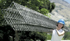
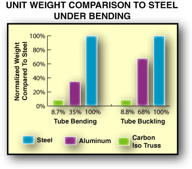
The extremely light weight of IsoTruss is dramatically demonstrated. Source: IsoTruss
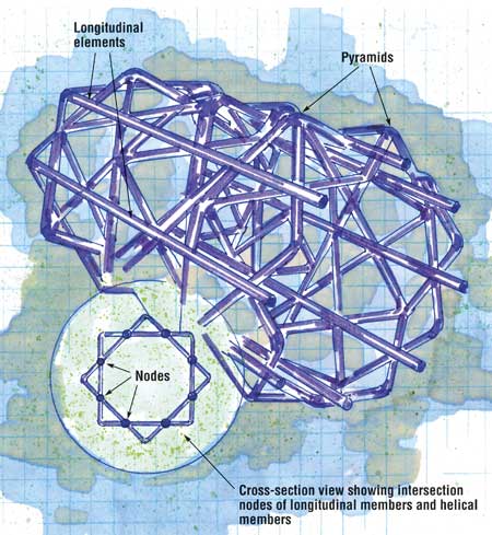
Illustration: Karl Reque
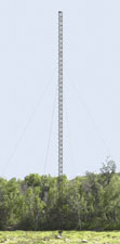
An actual IsoTruss guyed tower in service. Source: IsoTruss
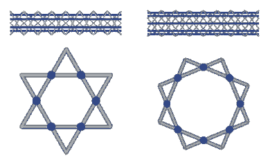
A schematic of a six-node and an eight-node IsoTruss design, with the longitudinal members highlighted in blue. Source: IsoTruss
Source: IsoTruss
Design Results:
- Composite lattice design is only 13 percent of the weight of a steel tube in bending applications, compared on an equal-load basis.
- Strength and stiffness can be tailored to each application through material selection and latice shape.
- Open structure and very low material content makes IsoTruss competitive with low-cost, noncomposite materials, such as wood.
Anyone who lives under a pitched roof can appreciate the concept of a truss — a simple network of members joined together to form a two-dimensional, rigid triangular shape that can support the weight of the roof. When the concept of a truss is combined with composite material in three dimensions, the result is an ultra-low-weight structure with a tremendous strength-to-weight advantage.


IsoTruss Structures Inc. (Brigham City, Utah) is counting on the potential afforded by this unique design concept. Initially developed and tested by researchers at Brigham Young University (Provo, Utah), the IsoTruss is a filament-wound, cage-like, open tubular lattice comprising a series of intersecting triangles and pyramids. IsoTruss Structures holds an exclusive license on the technology in the U.S.
The composite IsoTruss is similar in design to aluminum or steel lattice radio or telecommunication towers, says Tracy Livingston, chief technology officer at IsoTruss. A lattice design is usually selected for such structures because it uses less material and thus is about half the weight of a solid tube, which enables construction of very tall towers. The open structure also reduces wind loads.
A drawback of metallic lattice towers is that they are expensive because they are constructed of individual elements that must be hand assembled and fastened.
"What we have done is taken the best of both worlds," explains Livingston. "We have the material efficiencies of a lattice structure, for less material cost, and we have combined that with automated manufacturing, so we get the labor efficiencies, as well."
Incredible strength-to-weight
The overall structure of an IsoTruss is a cage-like tubular lattice, formed by a series of intersecting triangles. When viewed in cross-section, the all-composite structure appears as a symmetrical star shape — in three dimensions, the triangles form outward-pointing pyramids along the length of the structure.
The IsoTruss structure functions like a solid tube with a constant wall thickness, but at a fraction of the weight because so much less material is involved. In bending applications, it is less than 25 percent of the weight of an aluminum tube, and less than 9 percent of a steel tube, when compared on an equal load basis (see the bar chart, at right).
The lattice elements are unidirectional fiber tows or rovings, wound over a specialized collapsible metallic mandrel. Helical and longitudinal fibers are interwoven and compacted on the mandrel to form strong, integrated nodal joints. IsoTruss is designed to accept bending, buckling, axial, torsion and combined load applications. According to Livingston, the IsoTruss is well suited for situations with loads at multiple locations around the center axis or along its length. In effect, it is analogous to the geometry of an I-beam, with the longitudinal elements functioning like the flanges of the beam, moved outward from the neutral centerline tube axis.
For example, in an axial loading case, the longitudinal elements carry approximately 95 percent of the loads, while the helical triangular elements support the longitudinals, increasing the structural stiffness and protecting them from local buckling. In a torsional situation, the helical members take the majority of the load. The radial symmetry distributes the load and resists global buckling equally around the centerline axis. Livingston says that additional stiffness benefits are possible because of the loading along the fiber axis, which is the most efficient orientation possible.
"Because all the fibers are uniaxial, you get additional property improvement and damage tolerance because the load-bearing fibers are not off-axis," says Livingston. "For example, if you were to wind a solid tube structure with standard helical winding angles, and were using a low-modulus fiber, the fiber modulus might drop 50 percent or more because of the off-axis orientation. In our case, we can keep the modulus closer to 20 Msi," he explains.
The strength and stiffness of the structure can be tailored by customizing fiber and resin types and combinations, as well as the number of tows/rovings used, to create thicker or thinner elements. Hybrids also are possible with carbon for the longitudinals and glass for the helical elements, a solution that maximizes axial strength while saving material cost. For asymmetrical bending loads — more load in one direction — elliptical cross-sections also have been tried.
IsoTruss can be fabricated in configurations ranging from 6 to 12 nodes or pyramids. Livingston explains that an eight-node structure is more efficient in bending and resists buckling better because the longitudinal members are further away from the neutral axis — thus increasing the moment of inertia and, therefore, stiffness. A six-node structure has more resistance to side impact loads because the overall diameter is smaller and the pyramids are more prominent.
"Hooke's Law and the Parallel Axis theorem suggest that when designing tubes, the overall diameter should grow larger to increase the moment of inertia, or structural stiffness," says Livingston. "But, as the diameter grows, the wall thickness decreases to maintain efficiency, and the tube becomes fragile and susceptible to shell buckling failure, like crushing a soda can," he explains. Without solid walls, IsoTruss can be made with a larger diameter, constrained only by the compressive load limits distributed through the outside segments of the pyramids. The pyramids, in turn, transfer the side loads axially into the base segments of the pyramid and into the longitudinal members, in a much more efficient manner than an equivalent solid wall tube, according to IsoTruss. Extensive testing has proved that an IsoTruss lattice tube is twice as strong as a solid filament-wound composite tube, and requires less than half of the material.
"BYU has tested and validated this concept over seven years — they've done bending and axial buckling testing with the six-node and eight-node geometries, in different sizes, different lengths and different fiber/resin combinations," says IsoTruss CEO Christopher Derrington. "While they've proved the concept, what we've been working on over the last eighteen months is the manufacturing viability."
From design to manufacture
The challenge for the company has been to develop the design for manufacture and scale up the concept for real-world applications. Currently, IsoTruss is wound over a custom-designed, 25-ft collapsible and segmented metallic mandrel, using a lengthened single-head filament winder from Entec Composite Machines Inc. (Salt Lake City, Utah). A programmable logic controller manages the winding patterns. Single or multiple tows of continuous fiber (carbon, fiberglass, aramid or hybrids) — either in epoxy prepreg (towpreg) form or in a wet winding process with a range of resins — are wound over the mandrel. A number of carbon fiber suppliers are being considered, including Zoltek Corporation (St. Louis, Mo.), Grafil Inc. (Sacramento, Calif.) and Fortafil Fibers Inc. (Knoxville, Tenn.). Anywhere from 10 to 30 plies or passes make up one IsoTruss structure. The thickness of a completed wound element ranges from 6.5 mm/0.25 inch to 13 mm/0.5 inch. After cure, the mandrel is carefully disassembled and removed from the structure's interior.
To develop the different-sized triangular and pyramidal shapes, a different mandrel with specific protruding groove patterns is required for each type of node configuration. The company has spent considerable time and resources to develop a modular system of mandrels with interchangeable elements, in different lengths, notes Derrington.
"It has been a significant challenge to develop the mandrels economically so that we can make the products at high volume and keep costs down — our tooling development costs and time have been greater than we anticipated," he says. "But, we have met those challenges and we're ramping up for production." The company intends to purchase a three-spindle, 40-ft long winder for making parts at its current 25,000 ft² facility. There is enough room available for a six-fold facility size increase, if needed.
The company also has developed a design software package called IsoTruss Optimizer, which enables a design engineer to input loads and compute the truss size, the optimal materials (carbon, glass, aramid or a hybrid) and the material quantities required to replace a pole or tower made with traditional materials.
The largest IsoTruss product made to date is 40 cm/16 inches in diameter. However, the company is developing tooling to produce 0.62m/2-ft diameter by 6.2m/20-ft lengths that are fastened together with metal bolts. The joined segments will be used in towers and spans up to 86.2m/280 ft long for the initial application. Livingston says that the segments also can be fabricated with solid tube ends, which could be adhesively bonded together.
"In terms of scaling up to structures larger than 16 inches in diameter, well-proven mechanics show that it's scalable," he explains. "The near future holds promise for larger parts, in structures with heights and free spans of up to 500 ft."
Prototype towers have already been installed, and the company is taking orders for guyed towers for applications like meteorological instrumentation (anticipated delivery this month). Cooling tower columns and self-supporting utility poles will follow later in the year. Derrington points out that the IsoTruss design will allow for taller pole designs than existing fiberglass utility power poles. "Our technology allows us to go higher than 80 ft and to make very large utility transmission towers — we'll be going after those heights in 2004," he says.
Both men point out that while the current manufacturing method is adequate for larger structures, cost and productivity limitations encumber smaller diameter structures. A continuous automated process, similar to a braiding machine, is envisioned for the future to bring production costs down even lower, notes Livingston. The company also is receptive to licensing the technology for some applications.
"With the open structure and very low material content of IsoTruss pole products, and with its corrosion resistance and environmentally friendly materials, our costs are competitive with wood poles," says Livingston. "That's something the composite industry has not been able to do up to this point."


Related Content

Custom FR epoxy, hybrid glass/carbon fiber composites enable massive mosque ceiling expansion
Premier Composite Technologies delivered more than 25,000 FRP sandwich panels to massive Great Mosque of Mecca expansion, meeting weight, fire and 10,000 units/month goals.
Read More
BrainDrip scales up composite technology to meet current, future energy infrastructure needs
Next-generation composite pipe development with embedded, AI-enhanced health monitoring will modernize new and aging pipelines globally.
Read More
Composites end markets: Infrastructure and construction (2024)
Composites are increasingly used in applications like building facades, bridges, utility poles, wastewater treatment pipes, repair solutions and more.
Read More
Bedford introduces GFRP decking options for pedestrian bridges
Resilient composite decking includes PRODeck LV for light-duty pedestrian traffic, PRODeck H5 for heavy-duty or harsh environments and Southern Yellow Pine for pedestrian and equestrian bridges.
Read MoreRead Next

Scaling up, optimizing the flax fiber composite camper
Greenlander’s Sherpa RV cab, which is largely constructed from flax fiber/bio-epoxy sandwich panels, nears commercial production readiness and next-generation scale-up.
Read More
Cutting 100 pounds, certification time for the X-59 nose cone
Swift Engineering used HyperX software to remove 100 pounds from 38-foot graphite/epoxy cored nose cone for X-59 supersonic aircraft.
Read More
Ultrasonic welding for in-space manufacturing of CFRTP
Agile Ultrasonics and NASA trial robotic-compatible carbon fiber-reinforced thermoplastic ultrasonic welding technology for space structures.
Read More