
Thermoplastic composites gain leading edge on the A380
Breakthrough manufacturing process produces lightweight, affordable glass-reinforced PPS J-nose on the worlds largest commercial aircraft wing.
Share
Read Next


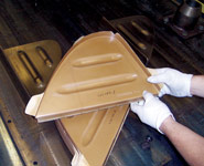
A technician removes a molded rib. Source: Stork Fokker
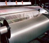
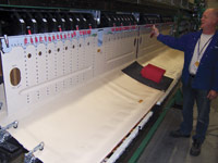
The weaving operation at Ten Cate, where Cetex semipreg is woven and partially impregnated for Stork Fokker. Source: Stork Fokker
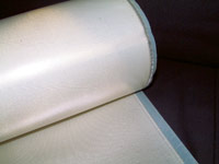
The finished Cetex semipreg combines 8-harness glass fiber reinforcement with a polyphenylene sulfide (PPS) matrix. Source: Stork Fokker
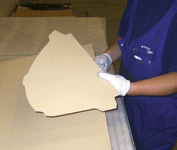
Thermoformable glass/PPS sheet, cut to size and ready for compression molding. Source: Stork Fokker
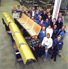
Source: Stork FokkerThe Stork Fokker manufacturing team for the A380 leading edge poses with three finished J-nose assemblies.
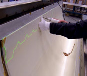
A technician prepares to lay up a semipreg ply, using a laser projection system. Source: Stork Fokker
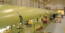
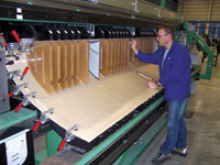
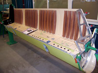
A wing's worth of the A380's J-nose. Source: Stork Fokker
The spar, the only component attached with fasteners, is positioned for attachment. Source: Stork Fokker
Ribs in place for welding. The ends of the metal mesh welding screens can be seen projecting out from under the rib ends. Source: Stork Fokker
A finished J-nose section, one of 16 per shipset for each A380 that will be built. Source: Stork Fokker
Compression molded stiffeners are placed for welding. Source: Stork Fokker
In the aerospace industry, where lightweight composites are prized primarily for their stiffness and strength, thermoplastics traditionally have taken a back seat to thermosets — with one very large exception. When Airbus Industrie's (Toulouse France) A340-600 commercial airliner entered service in 2002, fiberglass-reinforced thermoplastics formed the most inboard leading edge, often referred to as the J-nose due to its distinctive profile. Codeveloped by Airbus UK (Bristol, U.K.) and molder Stork Fokker AESP now GKN Fokker (Hoogeveen, The Netherlands), the monolithic structures — two per wing — replaced heavier five-part aluminum D-noses flanked by flat composite sandwich panels cored with Nomex honeycomb (DuPont Advanced Fiber Systems, Richmond, Va.) The result met all of Airbus' design requirements, beating out both thermoset composite and aluminum alloy alternatives, and securing a greater than 20% weight reduction, at a cost not significantly higher than aluminum (see HPC March/April 2000, p. 27).
Airbus took this unprecedented step to reduce not only weight but also impact damage from bird strike and debris, a perennial maintenance/repair problem, especially with the thin thermoset composite skins on the cored panels. The substitution proved so successful that, when Airbus recently rolled out its superjumbo A380, thermoplastic composites made up fully two-thirds of the fixed leading edge — eight parts per wing comprising a 26- meter length or 55 square meters of wing surface — running from each wing's inboard engine to its wingtip.


For the A380's outer leading edge, engineers redesigned the A340's thermoplastic composite J-nose, taking full advantage not only of thermoplastic toughness, but the relative ease with which it can be processed. Unlike thermosets, thermoplastics do not crosslink and cure and require no catalyst. They can be molded simply by heating them to temperatures that exceed their glass transition temperature (Tg), and they retain the new shape once cooled. More importantly, thermoplastics may be heated, reformed and cooled multiple times without loss of properties, a fact that had significant implications for cost-effective part fabrication.
Back to the beginning
When Airbus UK and Stork Fokker began work on the A340 inboard leading edge, the latter already had well over a decade of experience with fiber-reinforced thermoplastic composites (TPC) in aerospace applications. The first were developed in the 1980s for niche applications. Unlike the chopped fiber glass mat thermoplastic (GMT) and long fiber-reinforced thermoplastic (LFRT) materials used in a variety of low-load to semi-structural applications in automotive and other industries, aerospace-grade TPC more closely resemble thermoset advanced composites — employing continuous fiber reinforcement and advanced polymers. These TPC materials are available in a variety of forms, such as unidirectional and fabric-based prepregs, narrow tapes and commingled fibers, as well as pultruded sheets, tapes and rods.
The matrices differ as well. Early on, the matrix of choice was typically an amorphous polymer, such as polyethersulphone (PES) and polyetherimide (PEI). These were superseded by semi-crystalline polymers, such as polyphenylene sulphide (PPS), which offer increased resistance to solvents and other chemicals. (Note that the oil and gas industry lines the interior of downhole tubing with PPS and other thermoplastics because of their excellent resistance to gas and caustic chemicals used in oil production.) Early work with more advanced polymers, including polyetherketoneketone (PEKK) and poly-etheretherketone (PEEK) did not yield widespread applications due to the high cost of the resins, as well as the difficulties and cost of processing them at 250-350°C.
In the late '80s, thermoplastic sheet material was first used to form aircraft flooring via thermofolding. The process entails heating a very narrow straight band in a laminate along the intended crease line, mechanically bending the laminate to the desired angle and then allowing it to cool. Floor panels of glass-reinforced PEI and carbon fiber-reinforced CF/PEI sheet material were thermofolded 90° downward at the edges to produce a low-cost, durable edge closeout. Glass fiber-reinforced GF/PEI was used in Fokker 100 aircraft cargo flooring, while CF/PEI was used for floor panels in the Gulfstream G400 and G500 business jets and the Airbus Beluga transport aircraft (see HPC March/April 1999, p. 32). However, TPC materials were not limited to secondary and tertiary structures. "One of our early applications was the over-wing pressure bulkhead for the G500, which is a primary structure," explains Arnt Offringa, Stork Fokker's R&D director.
Production paradigm shift
Stork Fokker moved from flooring and trailing edges of rudders to more complex structures on the strength of the company's development of a practical method for welding reinforced thermoplastics. After investigating a variety of welding techniques in the early 1990s, including induction welding, resistance welding, ultrasonic welding and vibration welding, the company selected resistance welding as the optimal technique for producing cost-effective thermoplastic assemblies.
In resistance welding, specially made tooling is used to clamp a strip of metal mesh between two parts at the intended bond line. As clamp pressure is applied, an electrical current is passed through the mesh, quickly heating the mesh and adjacent part surfaces to the melt temperature of the thermoplastic matrix. The very thin, open mesh (~0.2 millimeters thick) remains in the joint without disrupting the bond. Heat is introduced into the structure only where it is required — i.e., at the interface between the two surfaces being joined. This limits the material melt zone, reducing the risk that part shape or dimensional stability will be compromised.
Welding proved to be a major breakthrough in production efficiency: The total time to weld is only a couple of minutes, so the process adapts well to production and can be automated. Moreover, bonded structural composites on aircraft are still required to be riveted by airworthiness authorities, but welded joints are not. Unlike an adhesive bond, which under a microscope retains a clearly defined joint line formed by the adhesive film, welded materials fuse (thoroughly intermix) through the weld line, becoming essentially a single part. Therefore, welding eliminated the time and labor involved in drilling and riveting as well as the cost of the expensive titanium rivets, not to mention the extra weight and cost of build-ups where holes were to be drilled.
Resistance welding was subsequently qualified on a CF/PPS main landing gear door for a Fokker 50 regional passenger aircraft in 1997. The door flew for 3.5 years with no detectable weld deterioration.
This success opened the door in the late 1990s for Stork Fokker to produce much larger monocoque structures by welding compression molded GF/PPS ribs and stiffeners to hand-laid autoclave-cured skins, producing a single, homogeneous, impact-resistant assembly. The A340-500/600 J-nose was the first part to take advantage of this technology and set the stage for work on the A380.
From A340 to A380
While the design drivers for the fixed leading edge of the A380 were the same as for the A340, the A380's unprecedented size and Airbus' aggressive weight goals fueled an even greater need to reduce weight at an acceptable cost while meeting load, deflection and impact-resistance requirements. Although a CF composite could have contributed significantly to weight reduction, the redesigned J-nose for the A380 retains the use of GF materials because the latter are stiff enough to resist deflection across the cross-section, in order to maintain the wing's aerodynamic shape, but can flex more easily along the wing's length.
However, a second-generation welding mesh was developed, which improved temperature distribution, and welding tools were refined, producing a joint with higher peel strength. This higher peel strength was exploited by modifying the shape of the ribs, which produced higher part strength overall. The end product required fewer ribs, which resulted in the use of less material and lower overall part weight and cost. This redesigned J-nose was compared to a conventional design and showed a more than 20% weight reduction. Thus, it was very attractive for use along the entire fixed leading edge of the wing, except for the most inboard section, where an aluminum droop-nose design was adopted. (In the droop-nose configuration, the leading edge hinges downward and is not compatible with the J-nose arrangement which stays fixed behind a slat.)
Adjusting for a jumbo J-nose
When the A340's J-nose development program began, Stork Fokker molded its parts from GF/PPS, trademarked Cetex, available only in preconsolidated sheets from Ten Cate Advanced Composites, now Toray Advanced Composites (TAC, Nijverdal, The Netherlands). The standard method of fabrication at that time was to compression mold parts such as ribs and stiffeners. However, the 3.5-meter-long skins of the A380's J-nose sections were too large to fit in a typical press. Also, the skin needed to be built up in certain areas to produce localized reinforcement. Stork Fokker and Ten Cate worked together to develop a semipreg, which could be laid up by hand and consolidated using specially developed bagging methods in an autoclave. The Cetex semipreg is made from 8-harness satin-weave GF fabric and PPS film produced by high-performance film extruders Lipp-Terler GmbH (Gaflenz, Austria) and AmCor Flexibles Gent (Gent, Belgium). Ten Cate applies a special sizing to the fabric to enhance the fiber/PPS bond. The fabric and film are then passed through heated rollers, which fuse the materials together but do not, as the name semipreg implies, fully impregnate the fabric (see Step 2).
The J-nose structure's exterior skin and spar are laid up using single plies of the 8-harness semipreg. Plies are cut with 2D cutting systems supplied by Lectra (Paris, France and Marietta, Ga.), from a CATIA design database. Stork Fokker develops the 2D patterns from the 3D product design, using CATIA V4 Composite Covering, a special translation software module developed by IBM and available through Dassault Systèmes (Blagnac, France and Woodland Hills, Calif.). Laser projection equipment supplied by Virtek Vision International (Waterloo, Ontario, Canada) is mounted overhead and used to position plies for build-ups and drop-offs to accommodate local loads and reinforce cutouts, with laminate thickness varying from 5 to 12 plies (Step 3).
Because the semipreg is a thermoplastic, it does not need to be stored in a freezer and thawed. Since the semipreg is not tacky, a handheld ultrasonic welder is used to fix the plies of semipreg into place. The part is also bagged a bit differently than a thermoset composite because the cure temperatures are so much higher — 250-350°C compared to 120-180°C for typical epoxy thermosets. The laminate is consolidated during autoclave cure using a similar autoclave pressure to that for thermosets, but the cycle is much shorter. "With thermoplastics, there is no chemical reaction taking place," says Offringa. "Therefore, there is more processing flexibility in the heating and cooling phases — this is a plus for thermoplastics." In addition, the PPS is a forgiving material: the skin laminate can be run through a second consolidation cycle if there is a bag leak or other fault.
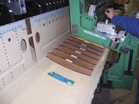
For the J-nose ribs and stiffeners, GKN Fokker still uses preconsolidated Cetex. Ten Cate lays up five plies of the material and debulks them, then delivers the result in 1.2 x 3.7-meter sheets to Stork Fokker, ready for compression molding. Precut blanks (Step 4) are loaded into the press, which operates at 350°C and 62 bar, to produce three to four ribs in a single press cycle that lasts about one minute (Step 5). Stiffeners are formed using the same process parameters, but more stiffeners are produced from each mold due to their smaller size.
An A380 shipset contains 16 J-nose assemblies, each measuring 3-4 meters. The various parts for each come together in a welding tool. Skin is laid in first, and then ribs are welded to the skin. The ribs have a flange running almost the entire length of the rib curvature in contact with the inside of the J-nose skin laminate (Step 6), maximizing weld area and eliminating the need for rivets. Next, the spar is placed and attached with mechanical fasteners (Step 7). Mechanical fasteners are used in this instance because resistance welding requires application of pressure on both parts during fusion. When the spar is located into the J-nose assembly, it forms a closed box and pressure cannot be applied effectively on the inside surface to be welded. Thus, in this case, mechanical fasteners are more practical in terms of both time and cost. Once the spar is secure, stiffeners are welded into place.
Airbus reports that feedback on the A380 J-nose already is very good. As the A380 undergoes testing in preparation for its final certification and entry into service, fatigue testing of the full-scale wing shows the J-nose performs exactly as predicted. Therefore, the company expects a long service life from the components.
"We are very pleased with the sequence used to develop this tech-nology, starting on a small scale with the A340 and then incorporating lessons learned on a larger scale with the A380," says Offringa. "This is the right way to implement new technology because there are always problems which must be worked out in the first application."
The future of aerospace RTC
Indeed, Stork Fokker believes there is still room for improvement to the J-nose, especially for leading edges with a smaller cross-section, such as those found on smaller aircraft and on the wing tips of wide-body aircraft. The goal is to further increase parts integration by replacing the separately molded skin and ribs with a skin featuring co-consolidated spars and/or stiffeners. Cost-to-weight studies have shown that the idea is feasible and manufacturing studies are ongoing.
Airbus continues to look at areas in its aircraft to increase and evolve its use of TPC, and appears on-track to substantially increase its usage. New-generation TPC materials are not only comparable to thermoset composites, with >50% fiber volume, but they also offer new and affordable weight savings via welding. For instance, control surfaces such as rudders and ailerons, which currently are built up from multiple parts that require rivets at their adhesive-bonded joints, offer potential for dramatic reduction in part and fastener count. If welded TPC materials were used, rivets could be eliminated. The fabrication process would include individual fabrication of the skin (co-consolidation and thermofolding), spars (co-consolidation) and ribs (compression molding), followed by welding of the rear spar, ribs and front spar to the skin. The next step in this technology is to integrate the rudder and aileron hinge brackets with their front spars.
Development of CF/PPS welding also is underway. Moreover, significant progress has been achieved in processing PEKK, which is attractive due to its higher Tg and resulting temperature capability in service. According to Offringa, "PEEK has too high of a processing temperature and remains too costly as a material. However, PEKK is doable." Offringa says Cytec Carbon Fibers LLC (West Paterson, N.J.), now Solvay Composite Materials (Alpharetta, Ga., U.S.), supplies a CF unitape which is available at an acceptable cost level and exhibits good mechanical and fire/smoke properties. Using PEKK, GKN Fokker is developing a floor beam for wide-body aircraft. The part is basically an I-beam with integrated vertical stiffeners to absorb the loads arising from height variations along the beam. Since there are a large number of these relatively same-sized structures per aircraft, the part is considered a good candidate for automating TPC processing. Several methods were investigated — compression molding in two halves; injection molding a complete part (less expensive but yields a heavier part); and butt-joining flat CF/PEKK laminate to I-beam web and flanges via co-consolidation. The latter method produced the lowest overall cost and weight.
"Using the knowledge from our initial solutions, it is then reasonable to have an outlook for larger volumes with future applications — a continuous process of proving out and advancing the technology," says Offringa.


Related Content

Plastic injection to composite overmolding: Evolving mold design for lightweight manufacturing
Hybrid molding is increasing for faster, high-volume production of more integrated parts, but success requires process knowledge which includes new mold developments as processes converge.
Read More
Ultrasonic welding for in-space manufacturing of CFRTP
Agile Ultrasonics and NASA trial robotic-compatible carbon fiber-reinforced thermoplastic ultrasonic welding technology for space structures.
Read More
Teijin Carbon, A&P Bimax TPUD braided fabric meets scalable composites manufacturing goals
A combination of Teijin Carbon’s UD thermoplastic tapes and A&P Technology’s braided fabrics translates into a PAEK biaxial fabric with minimal crimp, high drapability and other rate-enabling qualities.
Read More
Queen’s University Belfast presents research in thermoplastic drilling performance optimization
Researchers have published findings from a multi-objective optimization study on carbon fiber-reinforced PEKK drilling in an effort to better understand the material for use in aviation fastenings.
Read MoreRead Next

Polestar 5 takes aesthetics and circularity approach to biocomposite seatback design
The 2026 Polestar 5 expands the company’s use of sustainable materials design in the interior, including flax fiber/thermoplastic seatbacks that save 7 kilograms of weight and reduce overall plastics use.
Read More
Kaneka BMI material attains >25% lead time, >20% tool cost reductions in Janicki evaluations
Process evaluations find that novel BMI polymer chemistry addresses longstanding manufacturing challenges of BMI tooling prepregs while maintaining high temperature performance and durability.
Read More
Sentherm conductive polymers match aluminum thermal performance, cut weight
Tailored filler networks, anisotropic material design and manufacturing process control achieve hybrid polymers for EVs, batteries and other automotive-related electronics with 95% of aluminum’s thermal performance and 25-45% reduced component weight.
Read More