

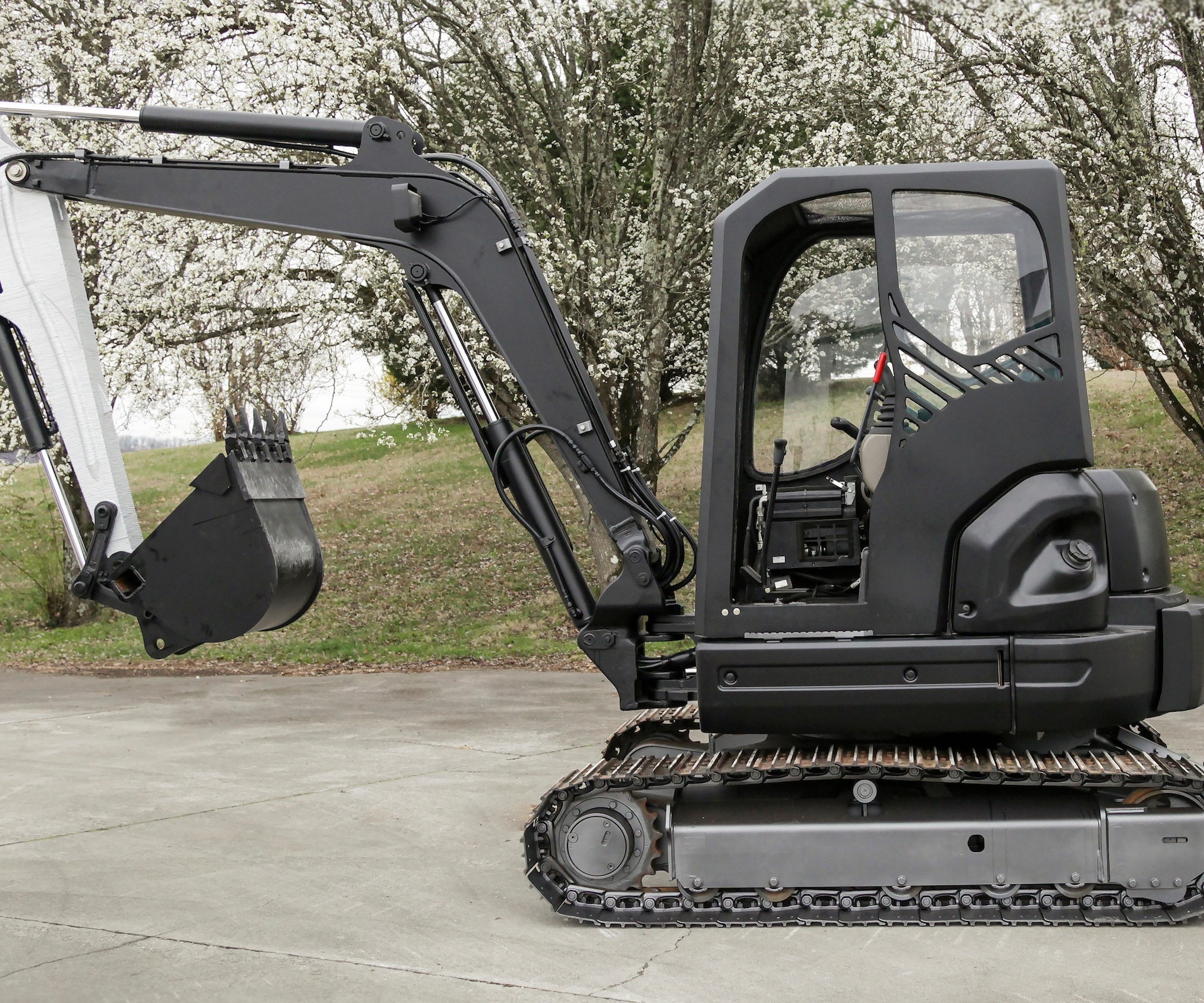
An additive manufacturing showpiece
A consortium of industry and academic partners collaborated in the design and build of the Additive Manufactured Excavator (AME), which was unveiled at the 2017 ConExpo/ConAGG show in Las Vegas. The fully functional, hydraulically powered excavator is the first such machine with critical components built by means of additive manufacturing, including its cab, 3D printed from carbon-fiber reinforced ABS.
Source | Carlos Jones / Oak Ridge National Laboratory / US Department of Energy
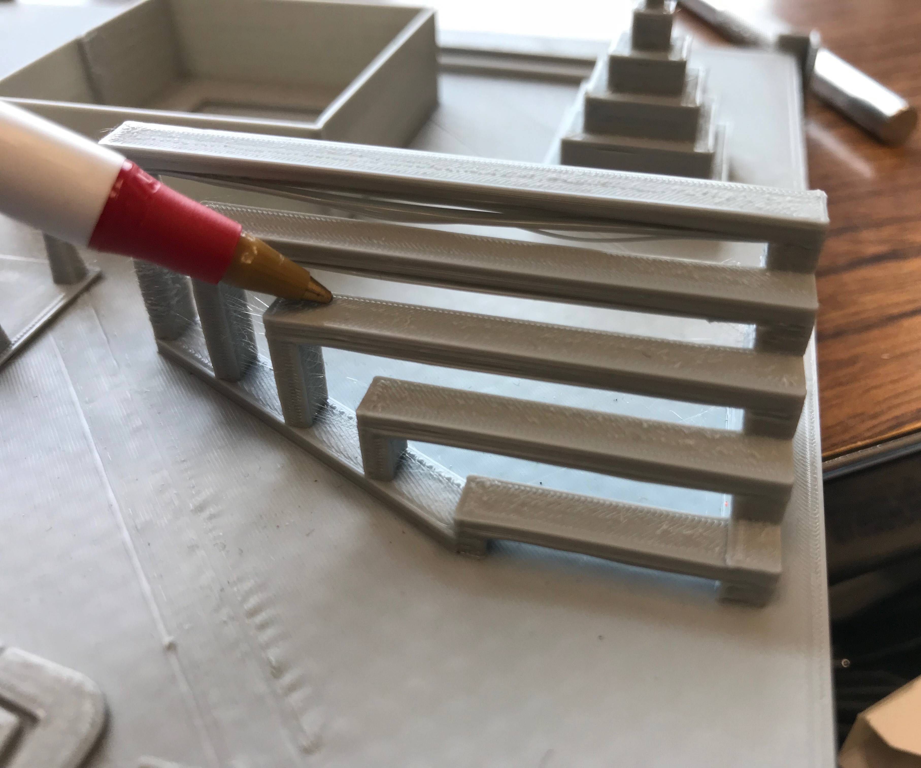
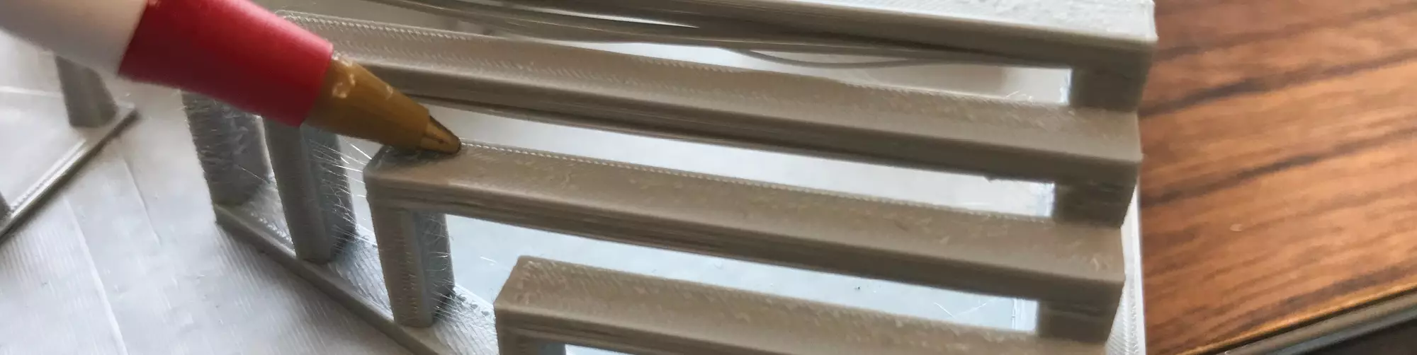
3D printing and bridging gaps
Small-format 3D printers can bridge a small gap during the printing process, because the very thin extruded bead cools and hardens in a fraction of a second. The volume of the bead extruded on the BAAM printer, however, typically needs a minute to cool. During that time, the weight of the bead could cause it to sag, so either the part or printing layers must be designed in a such a way that the printed beads aren’t required to bridge gaps or there is a means to support beads that must cross gaps of any significant length.
Source | Carlos Jones / Oak Ridge National Laboratory / US Department of Energy
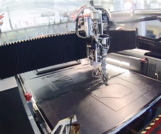
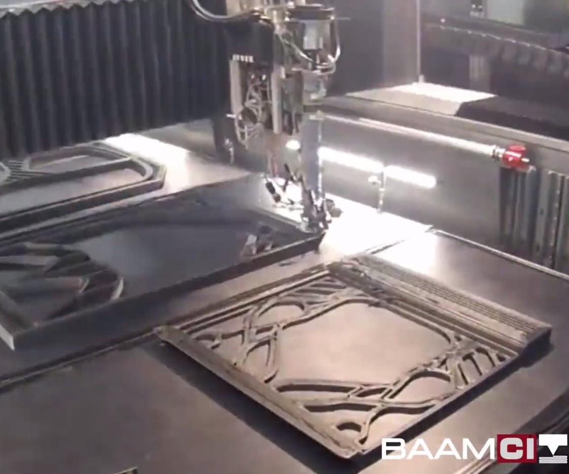
Step 1
The six cab parts were printed as two sets of three. Pictured here, the BAAM extruder head begins to print the parts by etching the outer part profile. The solid model of each part is exported as an STL file into a “slicer” software developed by ORNL. The program “slices” the part into discrete layers, which in turn are transformed into program code used by the machine to print the part.
Source | Carlos Jones / Oak Ridge National Laboratory / US Department of Energy
Step 2
As the printing process proceeds, bead layers increase part thickness, and the parts become more clearly defined. Pictured here, from upper left to lower right, are the left side of the cab, the front or windshield area panel, and the back wall of the cab. ORNL’s Size 2 BAAM has an estimated extruder speed of 2,500 IPM in the x and y directions, with a repeatability of ±0.005 in. Approximate bead width for the cab build was 0.15 in.
Source | Carlos Jones / Oak Ridge National Laboratory / US Department of Energy
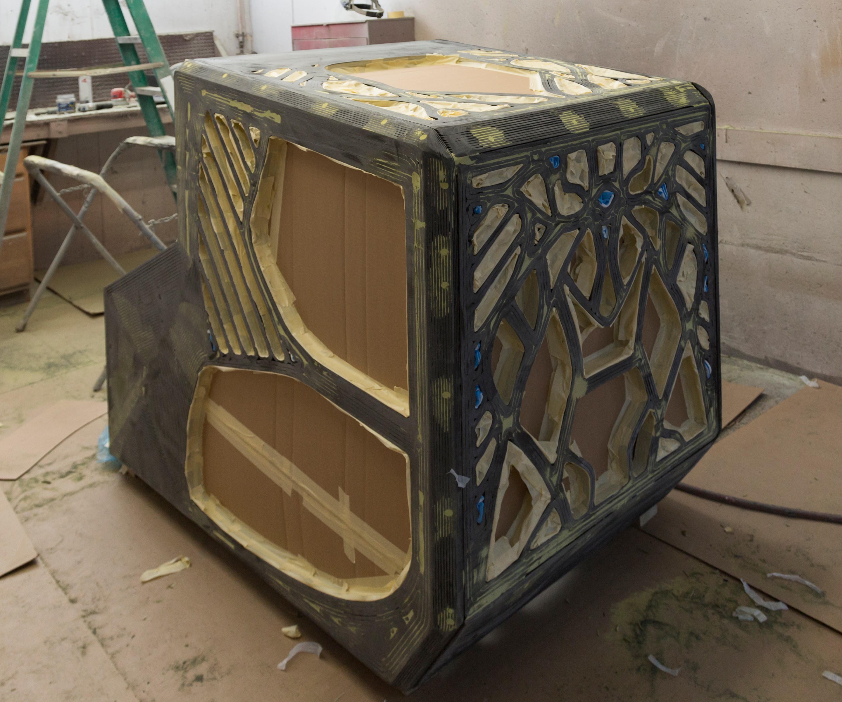
Step 3
After printing, the parts are assembled with a combination of snap-fit joints, screws and adhesive. After assembly, fastener holes are filled and the cab is masked, as shown here, to ensure that a patent-pending, self-leveling filler/coating to come is applied only to the external, paintable surfaces.
Source | Carlos Jones / Oak Ridge National Laboratory / US Department of Energy
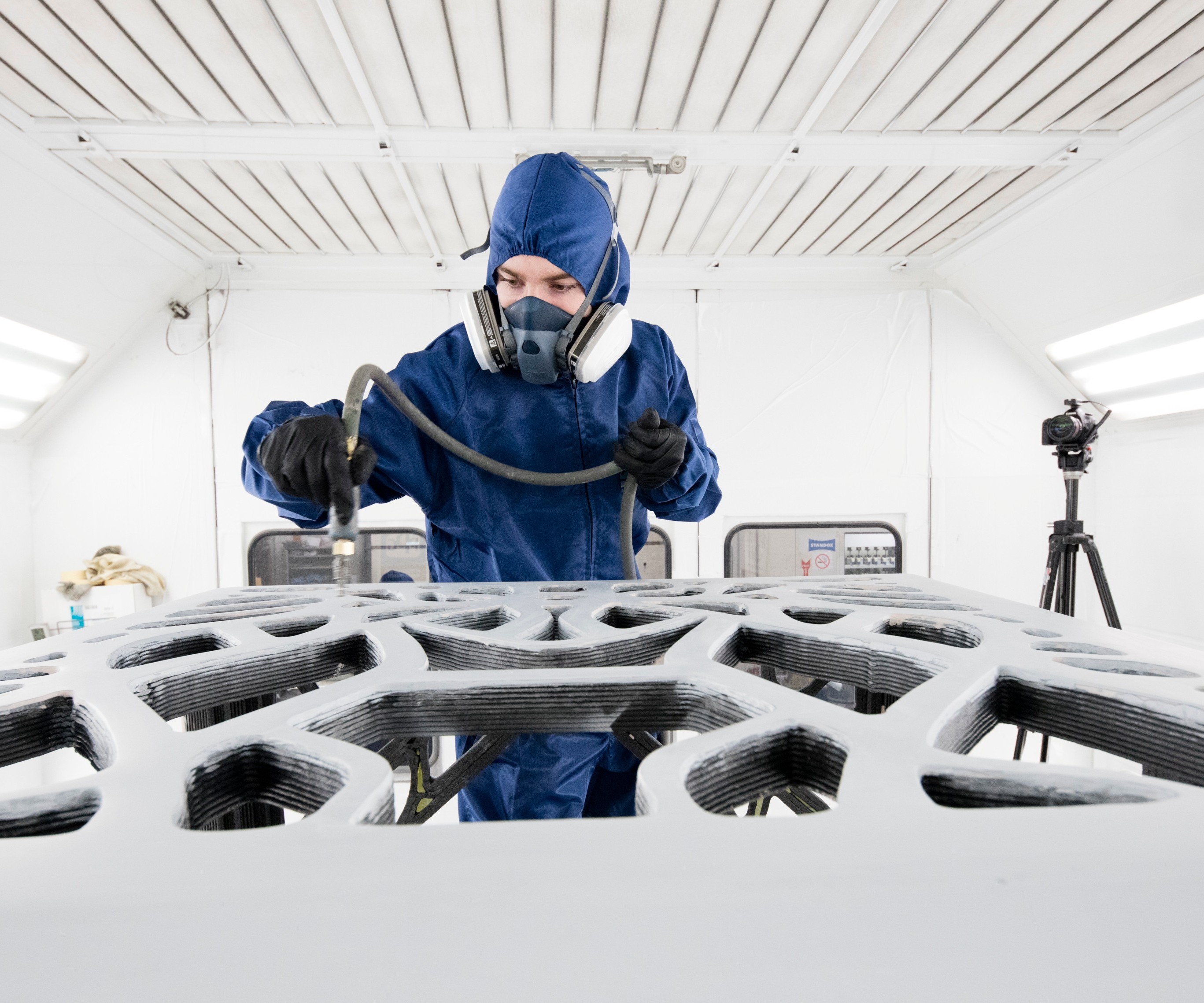
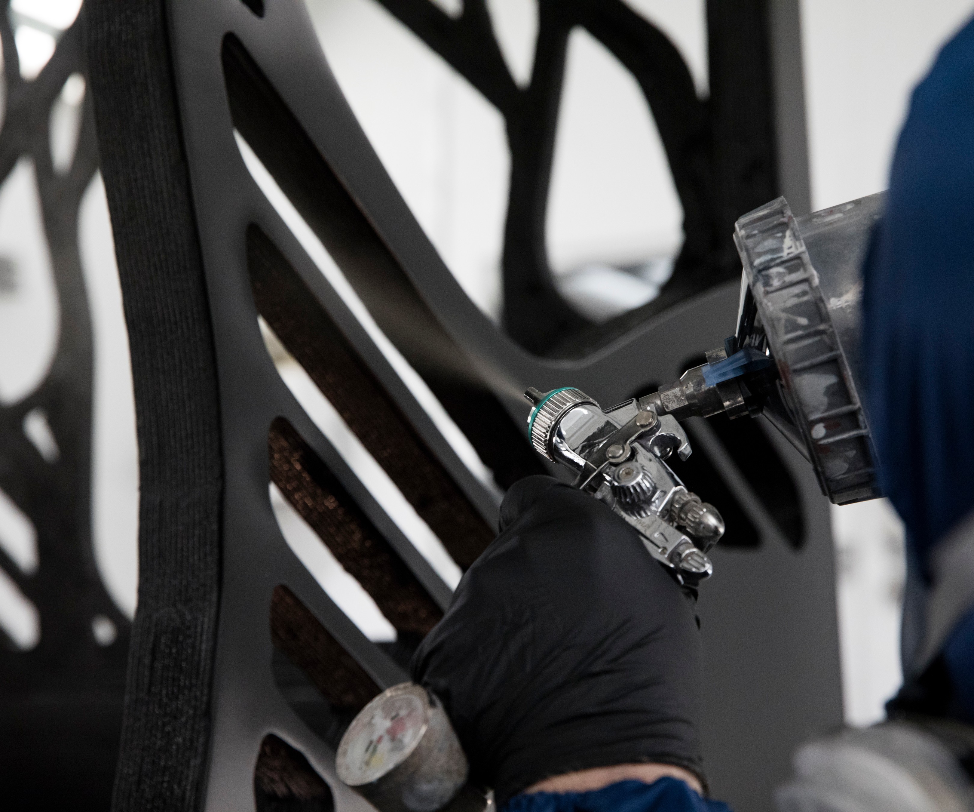
Step 4
The external surface of the cab is sprayed with the self-leveling filler/coating, which is formulated to hide the print lines and to chemically bond to the carbon fiber-reinforced ABS substrate to provide a paintable surface.
Source | Carlos Jones / Oak Ridge National Laboratory / US Department of Energy

Step 5
After spraying, the coating is dried and the surface and edges are sanded to provide a smooth, paintable surface. For precision production parts and molds, the thickness of the coating must be taken into account prior to printing to achieve the desired final thickness.
Source | Carlos Jones / Oak Ridge National Laboratory / US Department of Energy
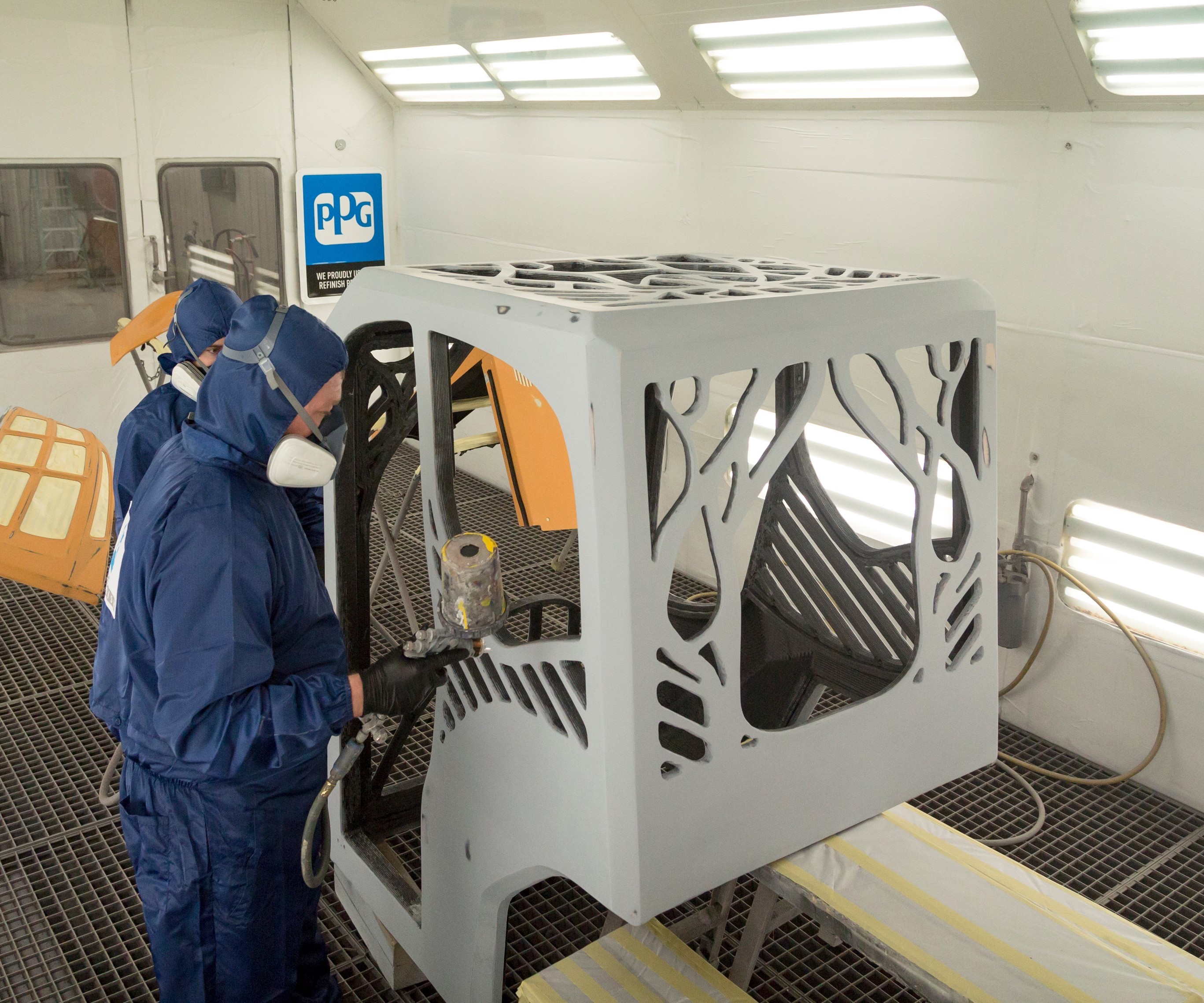
Step 6
After sanding, a primer is applied to the coated, external surface of the cab.
Source | Carlos Jones / Oak Ridge National Laboratory / US Department of Energy
Step 7
The proprietary coating facilitates easy application of paint to the carbon-fiber/ABS cab
Source | Carlos Jones / Oak Ridge National Laboratory / US Department of Energy
Step 8
In the final step, a clear-coat is applied to the paint, providing a Class A finish and gloss. Source | Carlos Jones / Oak Ridge National Laboratory / US Department of Energy


Large-format additive manufacturing (LFAM) is relatively new to the 3D printing marketplace but has quickly established a promising niche. Essentially, LFAM is a marriage of the motion systems used in today’s precision CNC-machining or laser-cutting machinery and 3D printing/extrusion heads modified for use in the larger format. Although much attention has been focused on using large-format 3D printers to build tooling for composite molding processes, they have also found use in building the finished parts themselves in one-off and very low-volume production. In either case, the technology is promising, and initial work, and the cost analyses derived from that work, suggests that large 3D printers, compared to current composite tooling and part fabrication practices, can offer significant cost savings, especially in total labor hours.
Benchmarking part-printing potential
Although development of the technology is ongoing, and the sample size of workpieces is still relatively small, an early demonstration project that entailed the printing of an excavator cab from carbon fiber-reinforced acrylonitrile butadiene styrene (ABS) provides a benchmark and insight into its capability to manufacture composite parts.


The cab was designed and manufactured by a consortium of industry and academic partners, called the Center for Compact and Efficient Fluid Power (Minneapolis, MN, US) using Cincinnati Inc.’s (Harrison, OH, US) trademarked Big Area Additive Manufacturing (BAAM) machine. The cab components were printed at the US Department of Energy’s Oak Ridge National Laboratory (ORNL) Manufacturing Demonstration Facility (Knoxville, TN, US). Together with a 7-ft (2.13m) long excavator arm, 3D-printed from carbon steel, and a 13-lb (5.9 kg) aluminum heat exchanger laser printed via a powder-bed-based process, the cab is one component of the first fully functional, hydraulically powered excavator with its key, critical components built using additive manufacturing technology. The project is referred to holistically as the Additive Manufactured Excavator (AME), and the machine was unveiled at the 2017 ConExpo/ConAGG show in Las Vegas, NV, US.
The cab was 3D printed with a ABS compound containing 20% chopped carbon fiber, supplied by Techmer PM (Clinton TN, US) and now trademarked as Electrafil ABS 1501 3DP. The resin is specially formulated for pellet-fed, large-format printing, which, depending on the application, may require higher stiffness than achievable with similar glass-filled formulations. The resin system has a reported flexural modulus of 1.8 msi, compared to Techmer’s 20% glass-filled grade, also targeted for BAAM applications, with a modulus of approximately 0.9 msi. The carbon fiber/ABS has a melt temperature in the 220-260°C range, a moisture content of 0.1% or less; and dries in approximately 4 hours at 80°C.
The 48-inch wide by 54-inch deep by 65-inch tall (1,219 mm by 1,372 mm by 1,651 mm) cab was printed in six separate parts (two sets of three) — four side panels (including a two-piece front panel comprising an upper and lower section) and a roof. The printer was Cincinnati’s Size-2 BAAM system, which has a build envelope of 240 by 90.74 by 72 inches (6,096 by 2,305 by 1,820 mm) in the x, y and z dimensions, respectively.
Rick Neff, Cincinnati’s additive manufacturing product and sales manager, says the critical components of the machine are the extruder and motion system, which facilitates fast, accurate part production. “We adapted a CNC motion system to a 3D printer, and program it with the same code we use for laser-cutting steel,” he says, noting that Cincinnati developed the machine in cooperation with ORNL. The system uses a lightweight aluminum/honeycomb gantry and brushless, magnetic linear servomotors with dynamic flow control that matches the extruder speed with motion of the head to deliver consistent bead width and placement. Nominal extruder speed is 2,500 ipm (63 m/min) in the x and y directions. Accuracy for absolute positioning and repeatability in the x and y axes is cited as ±0.005 inch (±0.127 mm).
Real-world prototype
Although the cab was built as a prototype demonstrator, Neff emphasizes actual real-world structural parameters figured into its design, because the AME was to be operational. “We didn’t just build a box with four windows,” he says, reporting that engineering students from the University of Illinois who participated in the project used CAD software to design the parts, optimize the topology and meet anticipated structural loads. A key concern in terms of loading was crush-resistant occupant protection in the event of a rollover. As a prototype, the cab was neither tested nor qualified to a formal crush-resistance standard, but the intent of it was inherent in the design. When the cab design was finished, the CAD model of its parts was evaluated for the best way to print them. Each individual solid-model part is exported as an STL file into “slicer” software developed internally at ORNL, which effectively slices the parts into discrete layers; these layers, programmed into machine code, form the base units, as it were, of the build using BAAM.
Each part was printed horizontally, on the BAMM machine bed, with wall thickness built up by laying successive beads of material over the semi-dry, solidified layers beneath it. The carbon fiber/ABS was extruded under approximately 13 MPa of pressure with a nominal bead width of about 0.25 inch (6.35 mm). Because the material requires about one minute to cool and solidify before another layer of material can be deposited over it, to avoid sag, distortion or other dislocation, the machine is programmed to avoid any machine lagtime by keeping the extruder busy elsewhere depositing beads, and then returning it to deposit another bead when a safe margin of safety for cooling has been allowed. The cab components have an average wall thickness of 1.5 inches (38.1 mm), or about 10 bead layers (see Steps 1 and 2, above).
The same, but a big difference
Small-scale 3D printing machines, using methods such as stereolithography (SLS) and fused deposition modeling (FDM) equipment, have been on the market for more than 20 years, whereas as large-format machines, BAAM is one or two current commercial options, have only been available recently, the two technologies invite comparison; the cab build highlights the similarities and differences.
For one, today’s LFAM systems use extruders modeled on or take their inspiration from the FDM systems used in the small-format 3D printer segment. The extrusion process and fundamentals of building up parts by layers are, except for scale, identical. “You can learn a lot about 3D printing from a desktop machine before you make a part on the BAAM,” Neff says. At the same time, he cautions, there are functional differences. A small-scale 3D printer, which typically is used to make models and prototype parts, extrudes a fine, thin bead of plastic, which cools and solidifies nearly instantly. There is, then, no necessity for the one-minute cooling interval noted above. This allows bridging between parts and part sections with no support structure. On the other hand, a large-format 3D printer, such as BAAM, is designed for commercial applications, so making large parts via extremely thin layers would be cost ineffective. Consequently, large 3D printers extrude a bead perhaps 25 or more times thicker. The thicker bead, however, won’t bridge much more than a very small gap, without sagging, a fact that has implications for part design (see the second photo, above, titled “3D printing and bridging gaps”).
A thicker, wider bead also precludes the printing of a part with smooth visible surfaces, necessitating finishing — machining, filling, sanding, priming and painting or other finish coating.
With that caveat, there is an exceptional upside in the potential to exploit a modelmaking/CNC machining-free way to make production tooling and a tooling-free way to make one-off and few-of-a-kind finished parts. Additive manufacturing allows you to redesign things in a way you never have before,” says Lonnie Love, a corporate research fellow at ORNL. Love, who oversaw the printing of the cab at Oak Ridge, says the slicing software is the critical component, which generates the toolpath and automates the process that enables CNC machining to become, essentially, CNC “adding.”
After printing, the parts were removed from the machine bed and the cab was assembled with a combination of snap-fit joints, screws and adhesive. The team used a rubber-hardened PLIOGRIP epoxy adhesive from Ashland (Columbus, OH, US), specially formulated for bonding plastic parts.
Once the cab was assembled, Tru-Design LLC (Knoxville, TN, US), a composite manufacturer and R&D company, and a member of the Oak Ridge Carbon Fiber Composites Consortium, carried out a detailed surface finishing process, entailing the following sequence of steps: masking, spraying of self-leveling filler/coating, sanding, applying of primer, painting and clearcoat (see photos).
PPG (Pittsburgh, PA, US) supplied the primer, paint and clearcoat. John Miller, VP of sales with Tru-Design, reports that the self-leveling filler/coating is a patent-pending material, called Tru-Design TD Coat RT, for achieving a Class A surface finish on carbon fiber-reinforced composite parts. Tru-Design, which had previously participated on a project to 3D print a Shelby Cobra body with BAAM (see for Detroit Auto Show”Shelby Cobra“ORNL ‘prints’ ), also conducted at ORNL, developed the material jointly with the Polynt-Reichhold Group (Durham, NC, US). The latter manufactures the product, which is sold exclusively by Tru-Design. Tru-Design now sells the Tru-Design TD Coat RT product for printed and molded composite tooling and parts, as well as a high-temperature version for tooling used in autoclaves.
Love calls the material a potential game-changer for achieving Class A finishes with carbon. “When the parts come off the printer they have a sort of corduroy, ribbed texture,” Love says. “In the Shelby project, we learned sanding on carbon-fiber reinforced plastic is a nightmare.”
The TD Coat RT, which cures in 4 hours at room temperature, serves a three-fold purpose: it fills the “corduroy” print lines and other surface imperfections, acts as a sealant and chemically bonds to the composite substrate. The coating provides, after a light hand-sanding, a smooth, paintable surface. Using the material, Love reports, the excavator cab surfaces were finished in a fraction of the time required for comparable surfaces on the Cobra.
For precision parts and most tooling, application of the coating must be accounted for in the thickness of the final printed part, Love says. In the case of the excavator cab, the effect of the coating on final thickness was insignificant. Of greater potential consequence, especially for the design of mating surfaces, is part shrinkage: The carbon fiber/ABS resin used to print the cab shrinks about 0.5%, a shrinkage rate similar to injection molded parts.
Going commercial in aerospace
Neff reports selling three BAAM systems to three customers, which now use them to make production tooling for aerospace composite parts. Indeed, tooling currently appears to be best near-term commercial application for LFAM. But Love believes there are certain applications in which using a large-format printer to directly manufacture one-off parts makes sense. He reports using ORNL’s BAAM machine to make furniture, including a bar counter, benches and stools, for a company pavilion at the 2016 Design Miami Show. In a unique twist to this project, the parts were made from a bio-composite, comprising bamboo fiber and PLA resin compounded by Techmer PM. The project consumed more than 10,000 lb of resin.
Large format 3D printing is admittedly in its early stages, with designers and fabricators still progressing through a learning curve while machine suppliers strive to enhance and hone features. On the wish list for Neff is off-the-shelf machine programming software, as well as a full suite of design optimization and simulation software for the additive process. Currently, he reports, design optimization relies too much on trial-and-error.
Already viable, LFAM’s wider adoption and commercial success hinges on how well it outperforms current toolmaking and fabricating practices. That, in turn, depends to a great degree on how soon and how extensively the wish lists of printer suppliers and users are granted and fulfilled.


.jpg;maxWidth=300;quality=90;format=webp)


Related Content

The state of recycled carbon fiber
As the need for carbon fiber rises, can recycling fill the gap?
Read More
Cryo-compressed hydrogen, the best solution for storage and refueling stations?
Cryomotive’s CRYOGAS solution claims the highest storage density, lowest refueling cost and widest operating range without H2 losses while using one-fifth the carbon fiber required in compressed gas tanks.
Read More
Materials & Processes: Composites fibers and resins
Compared to legacy materials like steel, aluminum, iron and titanium, composites are still coming of age, and only just now are being better understood by design and manufacturing engineers. However, composites’ physical properties — combined with unbeatable light weight — make them undeniably attractive.
Read More
Materials & Processes: Fibers for composites
The structural properties of composite materials are derived primarily from the fiber reinforcement. Fiber types, their manufacture, their uses and the end-market applications in which they find most use are described.
Read MoreRead Next

Composites end markets: Energy (2024)
Composites are used widely in oil/gas, wind and other renewable energy applications. Despite market challenges, growth potential and innovation for composites continue.
Read More
From the CW Archives: The tale of the thermoplastic cryotank
In 2006, guest columnist Bob Hartunian related the story of his efforts two decades prior, while at McDonnell Douglas, to develop a thermoplastic composite crytank for hydrogen storage. He learned a lot of lessons.
Read More
CW’s 2024 Top Shops survey offers new approach to benchmarking
Respondents that complete the survey by April 30, 2024, have the chance to be recognized as an honoree.
Read More