
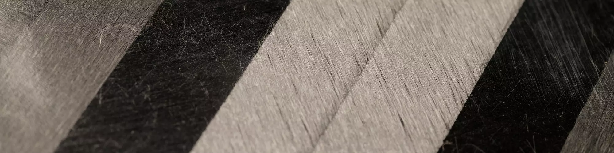


TuFF short fiber sheet material for affordable complex-shaped composite parts
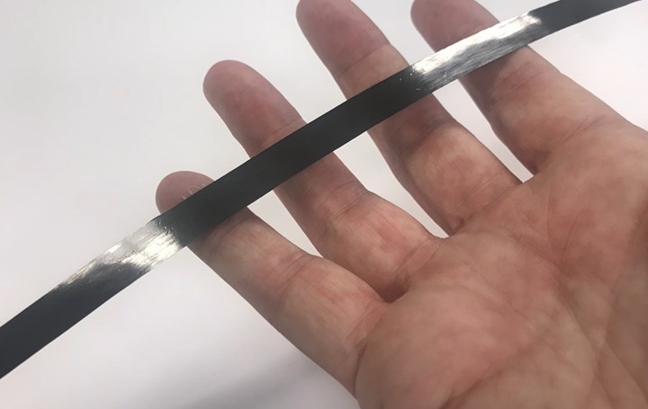
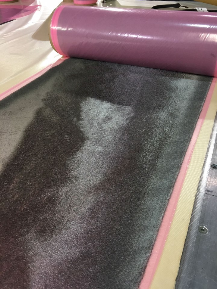
UD-CCM has developed the Tailorable Universal Feedstock for Forming (TuFF), a sheet material that attains UD prepreg-level fiber volume and properties (IM7 fiber shown here) thanks to a high degree of fiber alignment and length control, yet forms readily into complex shapes due to its in-plane stretchability. Source for all images | University of Delaware CCM
The Tailorable Feedstock and Forming (TFF) program was launched by The Defense Advanced Research Projects Agency (DARPA, Arlington, Va., U.S.) in 2015 to enable rapid, low-cost and agile manufacture of complex geometry composite parts that weigh less than 20 pounds. Composites win against metals for large, stiffened skins made with processes such as automated tape laying and fiber placement (ATL/AFP). However, more than 80% of the parts in a typical tactical military airframe are small with complex geometry. For these, machined aluminum is favored because of the high cost and complexity of composite materials and manufacturing for small parts.
“You can buy a 4- to 6-inch plate of aluminum, throw it in a CNC machining center and hit a button,” says composites industry and TFF program consultant Jeff Hendrix. “Although metal parts are cheaper to make, their additional weight and susceptibility to cracking and corrosion leads to sub-optimal performance of the system,” explains Mick Maher, the program manager in DARPA’s Defense Sciences Office who originated TFF. (Though Maher completed his five-year DARPA term in 2016, his vision for TFF is shared by current DARPA program manager Dr. Jan Vandenbrande.) Hendrix agrees but points out, “No one is going to pay double for the weight savings composites offer in these smaller parts; they must become more cost-competitive with aluminum.”


To achieve this vision, TFF is divided into two subprograms — the first for materials (feedstock) discussed here in Part 1 and the second for molding (forming) explored in next month’s Part 2:
- Tailorable Universal Feedstock for Forming (TuFF) led by the University of Delaware (UD) Center for Composite Materials (UD-CCM, Newark, Del., U.S.)
- RApid high-Performance Manufacturing (RAPM, pronounced “wrap-em”) led by The Boeing Co. (Chicago, Ill., U.S.).
The TuFF feedstock is a highly aligned, discontinuous fiber preform in thin-ply format, which can be combined with thermoplastic (TP) or thermoset (TS) resins for prepreg, or used in dry form for infusion-based processes. A patent-pending, discontinuous fiber alignment and preforming process has been demonstrated in a 5-ton/year pilot facility at UD-CCM comprising:
- Short fiber dispersion and alignment
- Automated layup and stacking
- Prepregging and tailored blank production
- TS/TP forming and liquid molding cell, to be added by the third quarter of 2020.
The alignment process is fiber agnostic, and TuFF preforms have been manufactured with aerospace-grade polyacrylonitrile (PAN) carbon fiber (e.g., IM7, T800), pitch carbon fiber, recycled carbon fiber, glass and ceramic fibers. Laminates with <1% voids and up to 63% fiber volume have demonstrated >40% biaxial in-plane strain capability during forming, enabling metals-like molding of complex geometries without darting or complex ply patterns. The pilot process line has also demonstrated closed-loop recycling and reuse of fiber from the TuFF process scrap, with the goal of enabling zero-waste manufacturing. TuFF was recognized at CAMX 2019 by the American Composites Manufacturers Assn. (ACMA; Arlington, Va., U.S.) with the Infinite Possibility for Market Growth Award, as part of its Awards for Composites Excellence (ACE) program.
Developing discontinuous fiber feedstock
Continuous carbon fiber poses two problems for TFF’s objectives: It is expensive and difficult to form into complex shapes. Short fiber offers formability, but current forms and processes, such as injection molding, do not deliver the high-fiber volume properties required (Fig. 1). There is also the issue of how to amortize high tooling and part development costs over an increasingly fragmented DoD market of more mission-specific platforms at lower volumes.
“This makes composite parts expensive for unique part/process/program certification,” adds Dr. John W. Gillespie, Jr., director of the UD-CCM and the TuFF principal investigator. The aim for TuFF, then, was to develop a material that demonstrates metal-like formability but can also be tailored to meet a range of DoD application needs and volumes.
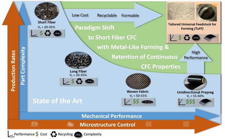
Fig. 1: Short fiber format, long fiber performance and formable for lower part cost
The goal of the DARPA-funded TuFF program is a universal material that can be tailored to meet specific part and program requirements, but still enable composites to win against machined aluminum for small parts (<10 kg) in defense applications, where the market penetration of composites remains small, even with the latest technology advances in commercial aircraft and automotive.
“The TuFF program was constructed to address several key challenges, including how to make short carbon fibers with smaller diameters to enable composites with aerospace properties,” Yarlagadda says. “The idea was to move to low-cost pitch precursors and make the short fiber directly instead of cutting continuous fiber, aiming toward IM [intermediate modulus] carbon fiber properties.” The program included Drexel University (Philadelphia, Pa., U.S.), Virginia Polytechnic Institute and State University (Blacksburg, Va., U.S.) and Clemson University (Clemson, S.C., U.S.) as subcontractors, with the latter performing most of the work on pitch fiber.
“This is a challenging problem because you’re looking at a process very different from what is used to produce continuous fiber,” Yarlagadda explains. Although multiple iterations of pitch fiber from Clemson have been evaluated, additional work beyond the DARPA TuFF project will be required to develop and mature the pitch fiber technology. Thus, the TuFF results presented here were achieved using commercial, continuous PAN fibers cut to short lengths. Cost implications are discussed below.
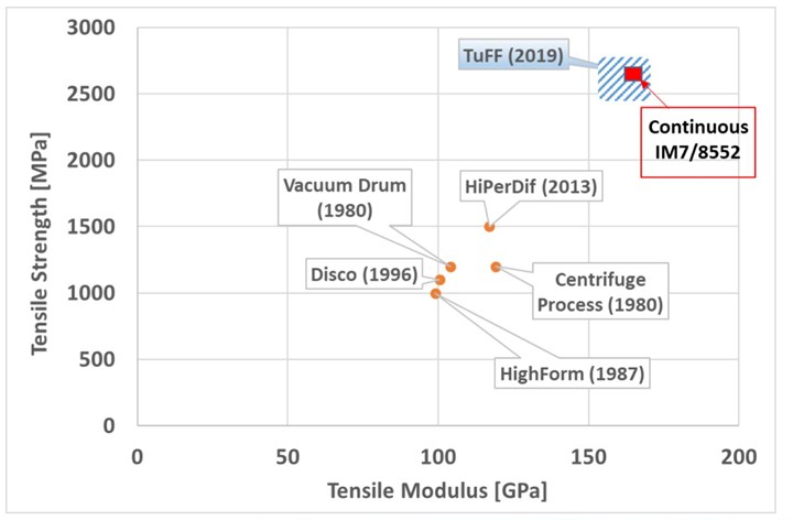
Fig. 2: History of short fiber materials
TuFF finally succeeds where previous efforts have failed due to its ability to tightly control fiber length and alignment with aspect ratios that lie within the sweet spot for formability.
Short carbon fiber solutions for affordable, formable composites have been sought for decades (Fig. 2), including DiscoTex, stretch-broken carbon fiber (SBCF) and HiPerDif (High Performance Discontinuous Fiber). For SBCF, a mechanical process breaks continuous PAN carbon fibers into lengths of 25-50 millimeters or longer (Learn More). For the 0.005-millimeter diameter IM7 carbon fiber (Hexcel, Stamford, Conn., U.S.) used, this gives an aspect ratio of 10,000. “An aspect ratio above 10,000 requires high forming forces,” explains Yarlagadda, noting the sweet spot for formability is an aspect ratio between 100 and 1,000. TuFF uses 3-millimeter-long IM7 fibers for an aspect ratio of 600.
“Technical papers were published from the late 1990s onward showing that short fibers with an aspect ratio of 100 should match the stiffness of continuous fibers, and with an aspect ratio of 1,000 they should match strength as well,” Yarlagadda says. “But there were issues with fiber alignment.”
HiPerDiF, developed by the University of Bristol (Bristol, U.K.), is capable of using a range of different carbon fiber feedstock lengths, from 1 to 12 millimeters long, that are suspended in water and deposited from nozzles onto a substrate to create an aligned fiber preform (Learn More). Thus, they have improved fiber alignment versus SBCF, but report 67% of the fibers within ±3 degrees from unidirectional. TuFF achieves >95% of fibers aligned within 5 degrees of the desired direction.
Controlled, uniform microstructure
“With this high level of fiber alignment, we can get to the same fiber volume as unidirectional prepreg,” explains Dirk Heider, assistant director of UD-CCM and also a TuFF project leader. He notes fiber volume control between 40% and 63% has been demonstrated for composites using 3-millimeter long IM7 carbon fiber.
The other key factor is fiber length control; 95% of the IM7 fibers measure 2.8 to 3.2 millimeters long (nominal 3 ±0.2 millimeters). “You want to have very consistent fiber lengths to optimize both mechanical and forming performance to achieve a repeatable process,” Gillespie explains. Heider adds that an IM7 fiber length of 3 millimeters is sufficient to give full property translation while reducing forming pressure and tooling cost. “We control the microstructure regardless of fiber type,” he observes. Yarlagadda adds, “If you have uniform microstructure, then you have a globally uniform response, resulting in consistent part thickness during forming.”
Is tow size a factor? “No,” Heider says. “You have to align at the filament level or else you don’t get this translation of properties and controlled microstructure. We receive chopped IM7 tows from an outside vendor and then filamentize by dispersing them in water. We then deposit the filaments as a sheet with a very high alignment, putting the fibers back together but in a very controlled way.” The patent-pending TuFF process produces thin-ply (8 microns thick) fiber sheets that can then be stacked into tailored layups, cut into blanks or slit into tapes. Thin-ply refers to a tow that is spread — e.g., a 5-millimeter- wide 12K high-strength (HS) carbon fiber tow is commonly spread to a 25-millimeter-wide tape (Learn More). “We have demonstrated a thin-ply tape that has very good steerability, achieving a radius of 1 inch, versus 40-50 inches for continuous fiber tapes,” Heider notes.
Heider says that with a standard modulus fiber, the diameter is roughly 7 microns (0.007 millimeters), which means a 4- to 5-millimeter fiber length for TuFF’s desired aspect ratio of 100-1,000. He also points out that composite properties depend not just on the fiber, but also on the resin and the resin-fiber interface. “We have been working with commercial fiber that is surface treated for aerospace thermoplastic and epoxy matrix resins, but not sized,” Heider says. “We have shown good bonding between our short fibers and the resin, which was reported in several papers presented at SAMPE 2019.”
Aerospace properties, metal-like formability
“We are testing the aligned short fiber material with PEI (polyetherimide) and PEKK (polyetherketoneketone) thermoplastics and Hexcel 8552 epoxy [used in HexPly unidirectional prepreg] to demonstrate aerospace-grade composite properties,” Gillespie says. Testing with PEI has been completed and shows composite properties that are equal to continuous carbon fiber across the board (Fig. 3), including tension, compression and shear as well as notched properties such as open-hole tension and compression (OHT/OHC) and bearing strength. Testing with PEKK and 8552 epoxy is ongoing and will be completed this year.
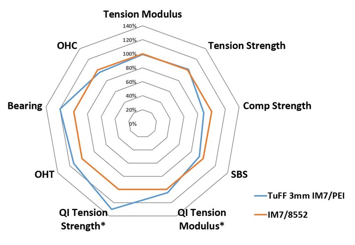
Fig.3: Attaining UD prepreg properties
TuFF has shown properties equal to UD prepreg and even an increase in certain properties for thin-ply (60 gsm/60-micron thick) IM7/PEI material compared to standard IM7/8552 epoxy prepreg in preliminary testing (see below), thanks to the thin-ply microstructure.
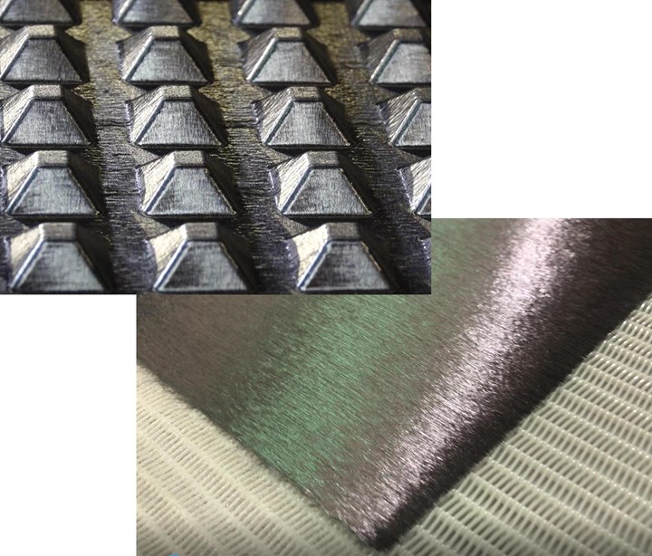
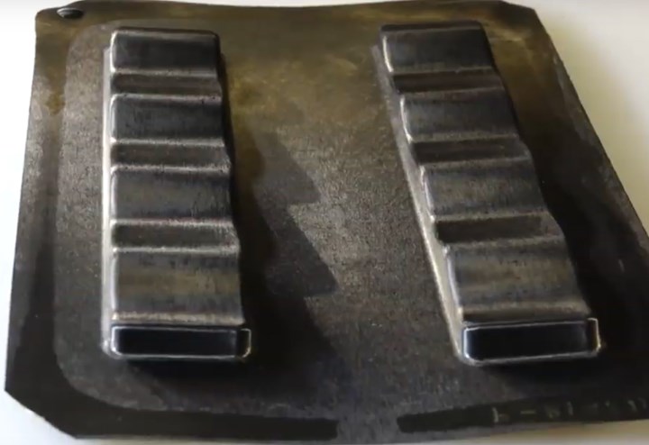
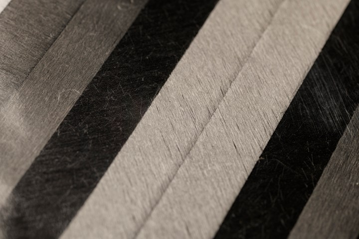
Fig. 4: Complex shapes, thin-ply tapes
TuFF’s short fiber and uniform microstructure enables forming aerospace-quality, complex shapes without high pressure or complex temperature control. The material can also be split into continuous tapes for use in AFP processing.
“We are able to produce composite laminates with less than 1% voids,” Yarlagadda says. “We have also demonstrated comparable properties to UD thermoset and thermoplastic prepregs, as well as some preliminary data for thin-ply TuFF formats.” Thin-ply reinforcements have been shown to increase load-carrying capacity and reduce crack propagation for higher damage tolerance (see Learn More). “This preliminary data shows tensile strength improvements of up to 30% due to the thin-ply microstructure,” Yarlagadda adds.
“The material is stretchable in-plane, so it’s formable like metal,” he adds. TuFF has formed part geometries with >40% biaxial strain. “We hold the boundary and shape it, very much like metal-forming processes.” TuFF formability has been demonstrated for a range of layups including 0- and 90-degree unidirectional (UD), 0/90 biaxial and quasi-isotropic. Images in Fig. 4 and in the video below (see Learn More) also demonstrate a range of complex-shaped parts. “We’ve started with thin parts because you cannot hide defects.”
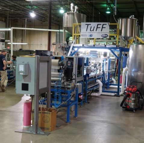
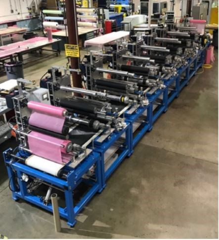
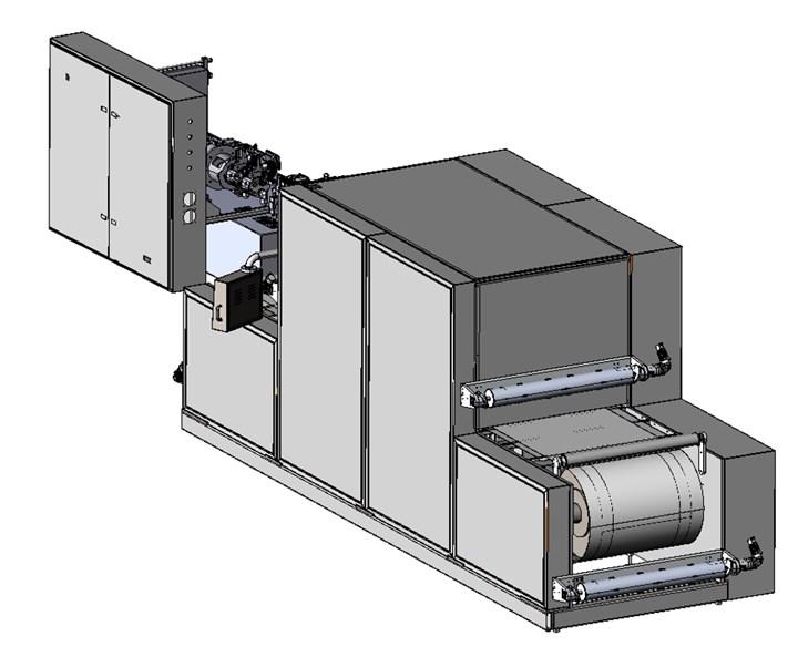
Fig. 5 – Fiber-to-parts pilot plant
UD-CCM has installed a 5 ton/yr pilot plant which produces continuous TuFF sheets and prepreg as well as tailored blanks that will be used in its flexible manufacturing cell for complex-shaped parts up to 0.9 by 1.2 meters (3 by 4 feet).
Alignment
Single TuFF thin-ply sheet (8 gsm)
Stacking
4-8 TuFF plies (30-60 gsm)
Prepregging
- Film impregnation (8 plies TuFF : 1 ply PEI)
(PEI film is 25 microns thick)
- TS prepreg equivalent : 24 TuFF plies (195 gsm)
- TP prepreg equivalent : 16 TuFF plies (130 gsm)
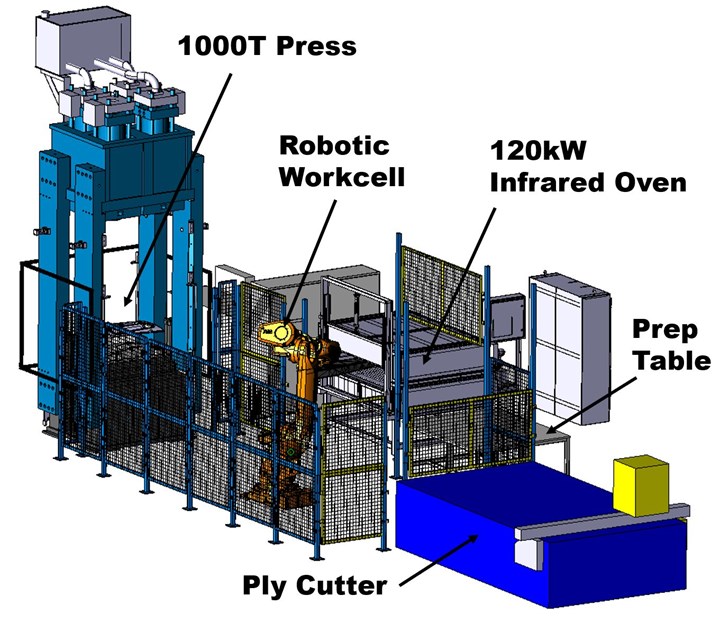
Forming cell
- Robotic workcell
- 120-kilowatt infrared oven
- 1000-ton press
- HP-RTM or wet compression molding
Fiber-to-parts pilot plant
“One of our objectives within this DARPA program was to move beyond a lab-scale system,” says Dr. John Tierney, senior scientist at UD-CCM and a TuFF co-inventor. “After several iterations, we currently have two, 24-inch-wide lines for making aligned, short-fiber sheets: a standard line and an off-axis line for producing angled fiber orientations (e.g., 45, 30, 60 degrees).” The standard sheet from these lines is a continuous, thin-ply material, 8 microns thick and roughly 8 grams/square meter (Fig. 5). The sheet is wound onto rolls, which are then loaded into an adjacent automated stacking system. Built in-house, this takes the individual rolls and stacks up to eight plies to build the desired fiber areal weight and fiber orientation layup, resulting in standard prepregs and blanks that are 30-190 grams/square meter and 30-190 microns thick.
“The third machine, for prepregging and tailored blank fabrication, is mostly off-the-shelf but customized to handle our material,” notes Yarlagadda. “Prior to this machine, we have been using a resin film process, layering our stacked sheets with resin film and then applying heat and pressure to consolidate. The semi-continuous indexing press design allows us to either make prepreg or tailored thermoplastic blanks.”
He explains that the process for making blanks is not an AFP process where tapes are applied to a rotating table. “It follows standard composite layup methods, where tailored blank design drives the layup sequence. What TuFF can do is to simplify blank geometry, eliminating complex darts and ply shapes, because the in-plane stretch capability allows complex shaping.” Heider explains that in the subsequent forming cell, which can produce parts up to 0.9 by 1.2 meters, “we’re typically using rectangular pre-consolidated blanks of specific layups and then molding those to shape, similar to sheet metal forming. We’re also creating dry blanks and molding them into shape for liquid resin infusion.” This work is being done with Composites Automation LLC, UD-CCM’s small-company incubator, also based in Newark. “The results look very promising,” Heider adds. “We can stabilize the material using a thermoplastic veil and then preform it easily, followed by infusion.”
Tierney emphasizes that this pilot plant with integrated automation and a capacity of 5 tons/year demonstrates the industrial scalability of the TuFF technology. “All of the hardware reflects what a full-scale plant looks like,” he explains. “It is currently supplying the materials needed for our materials characterization testing and forming demonstrations.”
Cost, fiber-to-part conversion, zero waste
TuFF has demonstrated its ability to meet aerospace performance with high formability, but what about low cost? “We are using continuous PAN fiber cut to short lengths,” Yarlagadda concedes. “However, there are commercial short fibers on the market from Toray, Hexcel, Teijin and others, as well as short fibers from recycled and waste stream sources. These fibers do not have the certification required for primary aerospace structures, but do have potential to significantly lower material cost for other applications.”
“Ultimately, it comes down to your fiber-to-part cost structure,” he continues. “With fabric and UD tape, you bear the cost of conversion from fiber to that form and then again to complex-geometry parts, with the latter generating significant scrap and molding risk due to complexity, defects, etc. By starting with continuous, certified fibers with subsequent cutting, we do get a bit of extra cost, but when we convert this to complex shapes, it is so much easier to form. So, there are advantages in avoiding complex patterns and layups, plus formability and lower scrap with TuFF for aerospace parts.”
Hendrix acknowledges that UD-CCM can form the kind of deep-draw parts that were a challenge for TFF’s RAPM program using continuous fiber materials (see upcoming Part 2). “TuFF enables making these parts using a half-dozen sheets versus 20 different subpreforms, which is key to achieving our cost target. They’ve also shown they can make geometries that can’t be made with traditional materials.” Yarlagadda cites the waffle part shown in the opening photo: “This is impossible with continuous fiber. How does that affect your value and business case calculations? This requires you to step back and ask how could you make parts now and what design freedom could you exploit?”
Heider returns to fiber cost and considers another factor: waste reuse. “If you don’t require certified fiber, it may be possible to use lower-cost short or recycled fiber.” Most recycled fiber is short fiber, because pyrolysis and some of the other processes require chopping before the resin can be removed from scrap prepreg and cured waste/end-of-life parts. “If you use short fiber forms as a starting point, all of your scrap can be reused, so that you essentially have a zero-waste manufacturing process,” Yarlagadda says. “This was not a focus of the DARPA TFF program, but we have shown we can recycle the TuFF material, put that fiber back through the TuFF process and get the same properties. DoD applications require certified aerospace-grade fiber, but we think the cost advantages of short fiber will still make it possible to significantly reduce cost.”
Next steps
“We want to finish the PEKK and 8552 epoxy property testing and then publish these results, as well as our work with various parts molding processes,” Gillespie says. “We have patents pending and are in the process of licensing the technology.” The DARPA TFF program officially ends in 2020, with all of the testing and results disseminated.
“When TFF was originally set up, the program was looking at why aren’t composites used more in defense and in automotive,” Gillespie says. “For automotive, it’s because they have invested in metals shaping and must re-invest for composites. But what happens when composites can be shaped like metal? Then it becomes easier to reconfigure existing production processes and leverage existing equipment.”
For Hendrix, the pressing issue is not high-volume production but how to achieve affordable weight savings at low volumes. “I don’t expect 10,000 aluminum parts to be replaced with 10,000 composite parts,” he acknowledges, “but I’ll take a couple hundred.” For that to happen, the next step is to take a handful of example parts and walk them through using these materials and processes, capable of aerospace quality, and validate the economics against machined aluminum.
In Part 2, CW will review the RAPM program, which is exploring a variety of processes in a reconfigurable manufacturing cell, featuring modular tooling and rapid heating/cooling with pixelated temperature control.


Related Content

Modular, robotic cells enable high-rate RTM using any material format
Airborne’s automated ply placement systems at Airbus, GKN Aerospace and Teijin Automotive Technologies aim to maximize flexibility and intelligent automation.
Read More
Price, performance, protection: EV battery enclosures, Part 1
Composite technologies are growing in use as suppliers continue efforts to meet more demanding requirements for EV battery enclosures.
Read More
Plant tour: ÉireComposites, Galway, Ireland
An in-house testing business and R&D focus has led to innovative materials use and projects in a range of markets, from civil aerospace to renewable energy to marine.
Read More
Plant tour: Albany Engineered Composites, Rochester, N.H., U.S.
Efficient, high-quality, well-controlled composites manufacturing at volume is the mantra for this 3D weaving specialist.
Read MoreRead Next

DARPA presents TFF program for low-cost composites for defense
Results reviewed at SAMPE 2019 show new materials and side-by-side comparisons of thermoset, thermoplastic, HP-RTM and press-forming, including PtFS molding cell.
Read More
Composites end markets: Energy (2024)
Composites are used widely in oil/gas, wind and other renewable energy applications. Despite market challenges, growth potential and innovation for composites continue.
Read More
CW’s 2024 Top Shops survey offers new approach to benchmarking
Respondents that complete the survey by April 30, 2024, have the chance to be recognized as an honoree.
Read More