


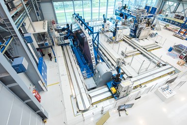
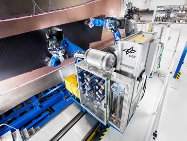
The German Aerospace Center (DLR) has developed GroFi, a multi-robot AFP/ATL manufacturing cell that aims to increase fabrication speed and efficiency for large aerospace composite parts. Source, all images | DLR
The current state of the art in automated fiber placement (AFP) and automated tape laying (ATL) of composite wings for commercial aircraft is based on a manufacturing model that assumes a mold oriented horizontally on a manufacturing floor, with a single AFP or ATL head acting on the mold from above, usually suspended by a gantry system.
Although this technology enabled the broader adoption of carbon fiber composites in aerostructures on the Boeing 787 and the Airbus A350, it likely is not sustainable for future aerocomposites manufacturing — particularly if, as expected, monthly deliveries for a next-generation single-aisle aircraft approach 100 shipsets. First, a horizontally oriented wing skin mold consumes much valuable footprint on the production floor. Second, AFP and ATL machines acting singly and serially are inherently inefficient.


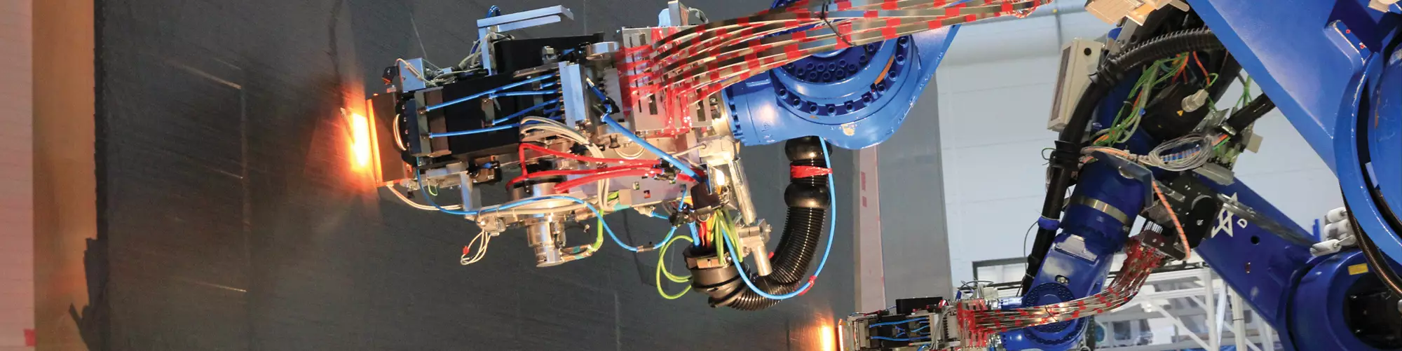
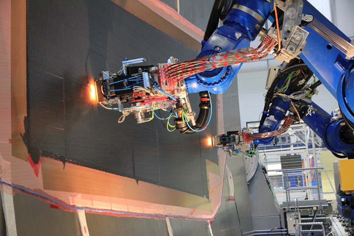
The GroFi system orients molds vertically and allows multi-axis AFP/ATL robots to move around the mold on electrified tracks. The robots work cooperatively to place material on the mold surface.
The solution to this problem is being explored by the German Aerospace Center (DLR, Stade, Germany) via its GroFi project, which launched in 2010 to develop technologies for high-rate, large-structure aerocomposites manufacturing. Christian Krombholz, research associate at DLR and coordinator of the GroFi project, says the technology has evolved to make two major changes in the AFP/ATL manufacturing strategy. In the first, the mold has been moved from its horizontal orientation and placed vertically on its edge. For the second change, AFP and ATL end effectors have been removed from the gantry, placed on multi-axis robots and multiplied. It is this multiplication of AFP/ATL machines that holds the most promise for making wing fabrication faster, more efficient and therefore more economic.
Krombholz says a wing skin fabrication cell, under the GroFi model constructed at DLR, comprises a vertically oriented wing skin mold surrounded by linear axis and turntables on which the robot units operate to place tapes and tows. Each robot unit includes the AFP/ATL head, the multi-axis robot itself, and a creel carrier that houses the carbon fiber tapes or tows. The multi-robot approach means that tapes and tows of varying quantities and widths can be deployed simultaneously, thereby increasing manufacturing capability and flexibility. To date, the GroFi system has evaluated AFP/ATL heads from Fives Cincinnati (Hebron, Ky., U.S.), Coriolis (Queven, France) and Broetje Automation (Rastede, Germany).
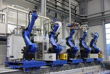
A GroFi cell includes a total of eight multi-axis robots, which allows for placement of tapes or tows in a variety of quantities and widths. Four robots would be in production as one time, with four more in ready-reserve.
In the GroFi cell DLR has constructed, five robots are available to work on any part of the mold simultaneously, moving around the molds on electrified tracks that obviate the need for cumbersome cabling. Depending on how many robots are working together on building up the laminate, the rest of the five robots are kept in ready-reserve to step in if a production robot needs replacement for lack of material, maintenance, malfunction, etc. Given the one-sided mold that DLR has deployed in GroFi, it is not difficult to imagine an even more complex and efficient cell, perhaps comprising multiple two-sided molds, with robots moving around and between each one to apply material.
However, just the deployment of multiple robots creates hurdles heretofore not encountered in composites manufacturing. “The challenge with this,” says Krombholz, “is developing the algorithms and software to program the robots.” This is not just a matter of making sure that each robot knows where it is in space relative to the other robots (and the mold) so as to avoid collision. Each robot also must work cooperatively with the others to place the correct material — tapes or tows — in the right place at the right time.
Krombholz says DLR has developed an algorithm that splits the laying operation between several robots on the same guide rail and optimizes scheduling. “The algorithm determines which robot performs which course most efficiently, taking into consideration geometric dependencies, approach paths and collision avoidance on the fly,” he says. “Path control, correction and quality control are implemented online for the production of aircraft-certified structures. This marks a huge step towards redundancy and robustness in production while speeding up the process using the given manufacturing infrastructure.”
The challenge of operating multiple robots is development of algorithms that coordinate robot behavior. Each robot must place the correct material in the correct place at the right time, and avoid collision with the other robots it’s working with. This system is targeted toward production of next-generation, single-aisle commercial aircraft wings.
The level of programming, algorithm development and machine learning required for such a system is without precedent in the composites industry and represents one of the biggest hurdles the GroFi program faces. Still, the potential benefits GroFi might convey to a commercial wing fabrication program are obvious, and not lost on the likes of a large commercial aircraft manufacturer, which is evaluating the technology to increase productivity of existing AFP / ATL plants. Meanwhile, GroFi has also stimulated more out-of-the-box thinking at DLR — a derivation of the multi-robot model.
From GroFi to Flappybot
Philipp Sämann, Dominik Delisle and Andreas Kolbe, research associates at DLR, looked at the GroFi cell and struck upon an idea that was first suggested somewhat jokingly: What if we put the mold back in its traditional horizontal position, kept the multiple AFP/ATL robots, but made them smaller and put them on wheels?
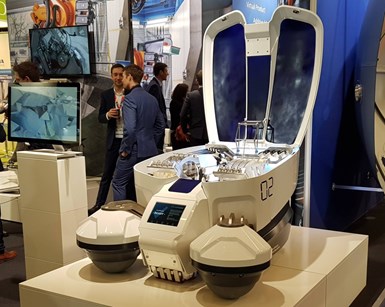
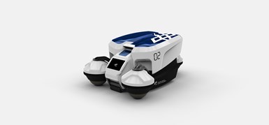
Growing out of the GroFi project at DLR is Flappybot, a three-roller, autonomous, modular AFP/ATL machine designed to drive on the the mold. Like GroFi, DLR envisions deploying multiple Flappybots simultaneously on a mold for the manufacture of large commercial aerostructures.
This technology, which is still in the early stages of development at DLR, is currently codenamed Flappybot (flexible autonomous production placement assembly robot); it takes all of the equipment and functionality of a fiber or tape placement system and encapsulates it in a modular, three-roller, self-driven, programmable, wireless robot that drives on the mold to place fiber and tape in the fabrication of a composite structure. It rides on three independently driven rollers and houses a sufficient number of spools of carbon fiber tape or tows for a laying width of 200 millimeters.
Sämann, coordinator of this technology, and his team pursued development of Flappybot and brought a mockup to JEC World 2019 in March. To reveal the concept at an early stage aims to assess market interest and to find out how the system might be evolved, modified and improved. “We had a lot of people at our stand looking at Flappybot,” Sämann says, noting that it acquired the nickname “AFP Crawler” among show attendees. “Many people see the potential,” he says.
Conceptually, the biggest hurdle to clear when thinking about Flappybot is just the very idea of a robot driving on a mold — driving on a laminate. It’s not only counter-intuitive, but it introduces a host of process control and quality concerns. DLR built a testing rig to investigate quality issues. Laminates of different thicknesses were built by conventional AFP systems; those laminates were rolled over several times with driven rollers to assess critical pressure, driving torque and wheels spin. Those laminates were then autoclave cured and tested. “We did not find that any harm was done to mechanical properties from Flappybot driving on the mold,” Sämann notes.
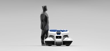
DLR says Flappybot weighs in at 350 kg, and the weight is needed to provide the compaction pressure AFP and ATL require. However, driving such a massive vehicle on a mold posses challenges. In early testing, however, DLR says the weight of the vehicle and the rollers it rides on do not degrade finished part quality.
Because of this, he says concerns were raised about Flappybot possibly breaking fibers or causing fiber misalignment. Further, there was anxiety about the rollers sticking to and “grabbing” prepreg that has already been placed. The team attempted to mitigate these risks by employing rollers that broadly distribute the mass of Flappybot. And the material used to make the rollers — rubber-coated steel — also helped reduce the propensity for sticking.
It gets complicated
Even if driving a massive robot on a mold is viable, there are other factors to consider, and most of these revolve around software and programming, says Sämann. First, DLR’s goal with Flappybot is to develop a solution that is cost-competitive with large ATL systems, particularly those used for commercial aircraft wing manufacture. Because of this, a large aerostructure would require multiple Flappybots working cooperatively. Sämann says DLR’s calculation tools determine the most efficient density of Flappybots per machining area. Given the size of a wing skin for long-haul aircraft, it would — depending on the exact configuration — take up to five units working simultaneously.
“Generating the paths (NC) that determine where the tows are placed, when and where they have to be cut, etc., is just the same as any other gantry system or articulated robot uses,” Sämann says. “It just depends on the design of the laminate. In the case of Flappybot, the software has to perform a precise path control because we have no guidance kinematics.”
However, thinking about five Flappybots working together on a wing, there is the distinct possibility of collision. “Crashing two massive units is something to avoid at any cost,” Sämann quips. As a result, his team is developing software and programming that allow for build priorities, build safety standards, tow/tape prioritization, dependencies and safety margins. This would include the use of onboard sensors to maintain safe distance from other Flappybots, along with governors to reduce speed within a given robot-to-robot distance.
“Our system is designed to decide over and over again which robot lays which tow, considering geometric dependencies in between tows and other boundary conditions such as collision prevention,” Sämann says. “The target is efficiency. The benefit is speed. Multiple robots cooperate while working on the same ply.”
Second, there is the matter of “referencing” — that is, making sure the Flappybot knows where it is on a mold. DLR is evaluating several solutions, says Sämann, including acoustic, optical, laser, induction and more. The technology chosen will likely come down to cost. In any case, there are two referencing strategy options. The first, and least complicated, is to develop a system that just tells Flappybot where it is on a particular mold. However, the most elegant solution, says Sämann, would be to reference Flappybot’s location on the mold and in three-dimensional space (i.e., the manufacturing space).
The programming and algorithm lessons being learned on GroFi have application for Flappybot as well. DLR says wing skin fabrication would require five Flappybots working simultaneously, so collision avoidance, material sequencing and other coordination will be critical.
Third, there is the matter of the rollers themselves, which, if not well controlled, could devolve to non-synchronous rotation, resulting in displaced or damaged fibers. “We want permanent all-roller drive,” Sämann says. “It makes it more challenging because we have no mechanical differential adapting each roller’s rotational speed when driving curves.” The software of the drivetrain, therefore, must calculate the real time rotational speed and direction of each roller to prevent wheelspin and displacement of fibers. That makes coding the drivetrain more extensive than just operating one roller.
DLR envisions eventual use of a simulation-based programming environment for Flappybot, similar to that used for current AFP/ATL systems. “This is where the process parameters are defined and translated to NC codes the machines/robots understand,” Sämann says.
There are other practical matters to consider as well. Chief among them is how Flappybot will be powered. Sämann notes that fiber placement requires heating of tows while laying them. A sufficiently large bank of batteries that enables extended use is heavy and bulky, thus DLR is evaluating in-situ contactless charging on the mold beside the laminate. Whatever solution will be selected, the energy capacity on board will not be the limiting factor when it comes to upscaling the part size.
And how would Flappybot behave when it runs out of fiber or tape? “The units need to track the current amount of material per spool on board,” Sämann says. “In case of running out of material during the next tow, or if there is an irregularity, it needs to go to a service station near the mold and communicate its absence to the other units.” At the service station, an operator would change the spool.
Where do we go from here?
Flappybot is not on the market, and probably needs a couple more years of developmental work before it can be commercialized. Sämann says that programming, in particular, must be evolved, fine-tuned and tested extensively. The cost and scope of this work is still being determined, and DLR is actively seeking industrial partners to help it progress the development work it has begun.
Sämann’s group is also working on fiber/tape placement head technology, as well as fiber and tape width options. The placement head, he says, would ideally come from an existing AFP/ATL equipment manufacturer to keep costs down. Width options would depend on the application and the processed material, but could range from less than 1 inch to more than 1 inch. “The aim is a plug-and-play solution for the layup head and the spool containers,” he says.
And, despite all the talk of AFP/ATL for aerostructures manufacture, Sämann says aerospace fabrication — because of qualification requirements — may not be a good starting point for Flappybot. He points to sailmaking (for racing yachts), architectural panels (for stadiums, bridges), and automotive battery covers as good initial targets. He envisions the possibility of Flappybot being deployed on-site to build highly customized composite structures that can be immediately installed. Flappybot could also be adapted for non-AFP/ATL work, including in-process or nondestructive inspection. In any case, Sämann notes, “It might be smarter to go for other applications first, which require lower payloads and energy consumption, to develop referencing, modeling, programming.”
For additional information about GroFi or Flappybot, contact Sämann via email at philipp.saemann@dlr.de.


.jpg;maxWidth=300;quality=90;format=webp)


Related Content

CW Tech Days webinar addresses emerging composites opportunities in infrastructure, construction
Attend this Dec. 1st interactive webinar sponsored by Composites One, where experts will review and evaluate the composite materials, processes and applications that should and will be considered for use in these markets.
Read More
Composite buildings go monocoque
Superior protection from the elements plus fast, affordable installation and maintenance have quickly made Orenco Composites’ DuraFiber buildings an attractive choice for water and wastewater, communications, transportation and power industry outbuildings.
Read More
Cleveland pedestrian drawbridge features FRP decking from Creative Composites Group
Lightweight molded panels with hybrid non-skid technology system make up the new double dutch-style bascule bridge completing Cleveland’s harbor loop.
Read More
Materials & Processes: Fibers for composites
The structural properties of composite materials are derived primarily from the fiber reinforcement. Fiber types, their manufacture, their uses and the end-market applications in which they find most use are described.
Read MoreRead Next

CW’s 2024 Top Shops survey offers new approach to benchmarking
Respondents that complete the survey by April 30, 2024, have the chance to be recognized as an honoree.
Read More
From the CW Archives: The tale of the thermoplastic cryotank
In 2006, guest columnist Bob Hartunian related the story of his efforts two decades prior, while at McDonnell Douglas, to develop a thermoplastic composite crytank for hydrogen storage. He learned a lot of lessons.
Read More
Composites end markets: Energy (2024)
Composites are used widely in oil/gas, wind and other renewable energy applications. Despite market challenges, growth potential and innovation for composites continue.
Read More