
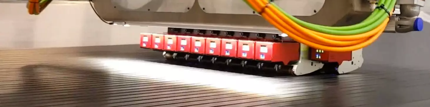


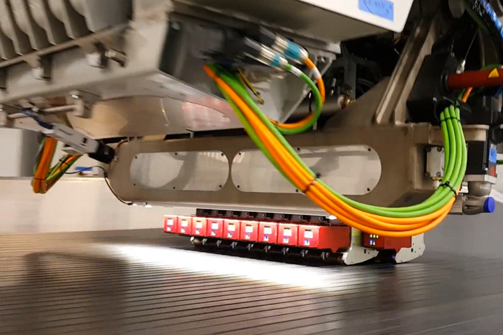
Close-up the Fives Lund Slalom ATL head. Each lane is individually controlled and actuated and allows for programmed laps and gaps. Photo Credit: Fives Lund
It is well understood that automated tape laying (ATL) and automated fiber placement (AFP) were the enabling technologies in the application of carbon fiber composites in major aerostructures for the Boeing 787 and the Airbus A350 aircraft. Prior to the development of these planes, composites had been applied in gradually increasing amounts in commercial aircraft for more than 30 years, but mainly in secondary structures using hand layup and some automated manufacturing processes.
With the 787 and the A350, however, Boeing (Seattle, Wash., U.S.) and Airbus (Toulouse, France) responded to demand for lighter weight aircraft, which accelerated adoption of composite materials and processes for use in fuselage skins, stringers, frames, wing skins, wing spars, wing boxes and tail structures. ATL and AFP led the charge, allowing each OEM, and their suppliers, to efficiently lay down large amounts of prepregged UD tapes and tows.


ATL found a place fabricating wing structures, which, being modestly contoured, took advantage of the wide format (3, 6 or 12 inches) of the tape products, which could be laid down quickly. However, what ATL offered in speed and volume it sacrificed in conformability.
AFP, on the other hand, which lays down multiple tows 0.125 to 0.5 inch wide, found a place fabricating fuselage and other more contoured structures that demand maximum flexibility and conformability. However, what ATL offered in conformability it sacrificed in speed and volume.
Further, as enabling as these technologies were, they clearly reflected the state of ATL/AFP art at the time of the planes’ initial development, almost 20 years ago now. Indeed, the production pace of the 787 and the A350 (each now less than 10/month in light of the coronavirus pandemic) is well-aligned with previous-generation ATL/AFP technologies, which are relatively slow. These technologies also depend on human operators to provide in-process visual inspection and quality control, checking for the laps, gaps, wrinkles, foreign object debris (FOD) and other flaws endemic to the automated laydown process. This quality control step represents a significant bottleneck in the manufacture of composite structures.
But as commercial aircraft manufacturers look to the future (well beyond the coronavirus pandemic) and the aircraft they will develop — particularly new single-aisle (NSA) programs to replace the Boeing 737 and Airbus A320 — shipset volumes are likely to be on the order of 60-100 per month. This demands composite materials and process capability orders of a magnitude more efficient than those used to fabricate structures for the 787 and the A350.
The Fives Lund SLALOM solution relies, in part, on individually actuated and compacted tape lanes. This enables substantially improved process control, including the ability to program laps and gaps according to allowables for the part. Source | Fives Lund
The best of both worlds
Thinking about all of this for the last few years has been Erik Lund, CEO of Fives Lund LLC and CTO of Fives Composites (Seattle, Wash., U.S.), a subsidiary of Fives Group (Paris, France), which also owns Fives Cincinnati, Fives Forest-Liné and Fives Liné Machines, which supply ATL and/or AFP machinery into the composites industry. Lund, in particular, has been contemplating ways to increase tape/tow laydown efficiency, studying and assessing the advantages and disadvantages of ATL and AFP in cooperation with the entire Fives Composites team.
Understanding ATL and AFP strengths (and weaknesses) first requires an understanding of the design allowables environment in which these processes operate. Lund points out, whether a fabricator is laying down tapes or tows, there are process-induced errors that must be tracked and measured. For example, when two tapes or tows are laid down next to each other, ideally their edges should abut, so as to provide an uninterrupted, even ply surface. However, machinery and material imperfections can create laps and gaps. Laps — short for overlaps — occur when two adjacent tapes or tows overlap each other during the laydown process. Conversely, when two adjacent tapes or tows “drift” away from each other, a gap can be created. A lap or a gap by itself is not necessarily problematic, so the width of each must be measured, and any that exceed the allowables specified for the part must be brought back into conformity, usually via manual rework.
As noted, ATL’s strengths lie in the fact that the process can quickly place large amounts of material over a large area. And as long as that area is flat or moderately contoured, tapes will not wrinkle or buckle. Further, because tapes are relatively wide, the total number of abutting tapes is relatively small, thus the opportunity for laps and gaps to develop is small compared to AFP. In this way, the ATL allowables environment is more forgiving.
Conversely, AFP, because it lays down multiple and smaller tows, can more easily steer those tows and conform material to complex and contoured surfaces. However, the opportunity for laps and gaps is greater — consider that a 24-tow AFP head alone theoretically presents 23 opportunities for laps and gaps — and thus they must be more closely monitored, often manually. Lund notes that many AFP allowables limit lap or gap violations over a given linear distance of material laid (usually 12 inches). Moreover, he says, laps and gaps that accumulate in a given area from layer to layer can also run afoul of allowables limits.
Another shortcoming of AFP is that the complex mechanical packaging in the laydown head leaves room for only so much hardware. As a result, all of the tows are compacted onto the tool surface by a single compaction roller. For wide AFP heads (24-32 tows), it can be difficult for the roller to provide uniform and consistent compaction pressure to each tow, which can affect ultimate laminate quality. For similar reasons, compaction consistency in ATL can also be a challenge, Lund contends, noting that “rework by operators, especially with 6-inch tape, can affect overall laminate quality.”
The multiple tows in AFP, on the other hand, also provide a sometimes-overlooked benefit of the process: When placing material at a non-0 or non-90 degree ply boundary angle, an AFP head has the ability to independently cut each tow at the boundary and thus create a crenulated ply boundary. Such boundary crenulations help optimize material use in a way that is not possible with ATL, which by necessity relies, says Lund, on “complicated cuts” to build an engineered ply boundary.
The solution: narrow tapes
Lund says he and others at Fives Lund and Boeing considered this complex world of fiber and tape placement and wondered if there was a middle ground to be exploited. They sought opportunities to leverage and integrate the advantages of ATL and AFP and focused on a material and process combination that is working today and shows substantial promise for next-generation, high-rate aircraft production.
“We were trying to achieve the conformability of AFP. We were also trying to get the benefit of crenulations at the boundaries,” Lund says. “At the same time, we wanted the gap tolerances and allowables of ATL. The question was, ‘What is the narrowest tape we can use that still employs tape allowables?’” The options were many, considering the narrowest tapes were 3 inches and the widest tows were 0.5 inch. However, Lund says, from an allowables and lap/gap tolerance perspective, there is a point at which a tape becomes a tow, and he wanted not to go past that point. “It took us about 30 minutes to settle on 1.5 inches as the tape width we would use,” Lund remembers. “And we have thanked ourselves for that decision. What we developed would not have been mechanically possible with anything narrower.”
Of course, the system Lund developed is not just a head that lays down 1.5-inch tapes. As a hybrid of AFP and ATL, it has features common to both. First, each 1.5-inch tape lane is individually controlled for tape supply and has its own compaction roller, actuated independently from the other lanes. This allows compaction pressure to be individually programmed and controlled by tape lane. Second, as with AFP, each tape is individually added and cut at the ply boundary, which allows for the crenulations that Lund coveted.
Third, and perhaps most significantly, the system features inline sensing technology. This system works in conjunction with each independently positioned and servo-adjustable tape lane, which Lund says can easily control spacing between tapes. In short, the system allows programmable laps and gaps. Lund calls it “dial-a-gap” and says it gives the operator the option of programming overlaps or to open up gaps to meet different gap averages and to change each lane to a specific gap width. Further, the system can see patterns, measure standard deviations and then adjust to the overall mean or even for specific regions of the laminate.
“It statistically looks at lanes per pass and draws conclusions based on accumulation of data,” Lund says. “You can then thin the laminate in certain areas if the gaps can be properly managed and controlled.” Ultimately, says Lund, such tight process control, combined with machine learning, “represents the evolution of inspection to develop data you can trust. This elevates capability and expectations and minimizes variation.”
Lund says this 1.5-inch tape machine — now commercialized as Fives Lund SLALOM — was developed in cooperation with Boeing, which owns some of the key intellectual property, including the independent compaction roller system. Fives Lund also worked closely with Boeing to qualify the 1.5-inch tape system. Three 19-lane Slalom machines have been in use for six years by Mitsubishi Heavy Industries (MHI, Tokyo, Japan) to fabricate wing skins for the Boeing 787. The three first-generation MHI machines, Lund says, add, lay and cut tapes at 0.6 meters per second. However, current technology being tested by Fives Lund has achieved aerospace tape laying tolerances and reliability with add speeds of 2.5 meters per second and lay/cut speeds of 4.5 meters per second using no heat to achieve consistent compaction. “There’s not a lot of automation this size that goes that fast regardless of application,” Lund says. “We underestimated the ultimate speed the composites would allow and had to redesign other manufacturing systems for the higher speeds and accelerations we wanted.”
What the future may hold
Looking ahead at a potential single-aisle replacement program building 60-100 planes per month, Lund says 1.5-inch tapes are a good fit for the fabrication of stringers, spars, wing skins and horizontal and vertical stabilizers. They can also be used to build flat laminates that are subsequently shaped and pressed, allowing for tailored compaction and shear considerations. Lund also acknowledges the biggest hurdle 1.5-inch tapes face is their “lack of institutionalization. There is very little history, very few channels in which to operate where 1.5-inch tape is being used.”
That said, he believes narrows tapes answer the technical and rate questions the commercial aerospace industry is posing. Lund is thinking particularly about his 1.5-inch prepregged tapes compared to competing processes, like liquid resin infusion, which uses dry fiber. Airbus, through its Wing of Tomorrow program, is evaluating dry fiber infusion to fabricate wing structures for its single-aisle replacement. Lund argues that in a single-aisle production environment where carbon fiber composite wings are being fabricated, the critical process parameter will be tool start-to-start time: “The question is, ‘How many tools do you need to meet rate?’ Tools must be measured by throughput and utilization, and dry fiber processes doesn’t free up that tool any sooner.” With a well-managed 1.5-inch tape system, Lund contends, “you should be going from freezer to cure in 2-3 days max. If you can do that, then prepreg out-time is just part of the manufacturing ‘noise.’”
Although the coronavirus pandemic has thrown a wrench into planning and development of new commercial aircraft, Lund believes the long-term outlook for commercial air travel is generally positive, and that development of next-generation materials and processes for this critical end market should and will continue at a brisk pace. “The commercial aerospace needs have driven the market for ATL and AFP, but as they recover we’re looking to other industries that have less history to overcome with this new technology.”


.jpg;maxWidth=300;quality=90;format=webp)


Related Content

Plant tour: Joby Aviation, Marina, Calif., U.S.
As the advanced air mobility market begins to take shape, market leader Joby Aviation works to industrialize composites manufacturing for its first-generation, composites-intensive, all-electric air taxi.
Read More
Cycling forward with bike frame materials and processes
Fine-tuning of conventional materials and processes characterizes today’s CFRP bicycle frame manufacturing, whether in the large factories of Asia or at reshored facilities in North America and Europe. Thermoplastic resins and automated processes are on the horizon, though likely years away from high-volume production levels.
Read More
The making of carbon fiber
A look at the process by which precursor becomes carbon fiber through a careful (and mostly proprietary) manipulation of temperature and tension.
Read More
One-piece, one-shot, 17-meter wing spar for high-rate aircraft manufacture
GKN Aerospace has spent the last five years developing materials strategies and resin transfer molding (RTM) for an aircraft trailing edge wing spar for the Airbus Wing of Tomorrow program.
Read MoreRead Next

Evolving AFP for the next generation
‘Aerospace quality at automotive pace’ is the mantra of the supply chain being developed for next-generation commercial aircraft. Automation is evolving to meet the challenge.
Read More
Strata automates Airbus A350 inboard flap production line
With two MTorres automated tape laying (ATL) machines, the UAE-based aerostructures manufacturer plans to reduce processing times for aircraft components.
Read More
From the CW Archives: The tale of the thermoplastic cryotank
In 2006, guest columnist Bob Hartunian related the story of his efforts two decades prior, while at McDonnell Douglas, to develop a thermoplastic composite crytank for hydrogen storage. He learned a lot of lessons.
Read More