
Hybrid thermoplastics give load floor impact strength
Project leads to development of new compression process for selective application of D-LFT on UD tape laminates.

Lighter, more energy-absorbing battery-electric vehicle structures
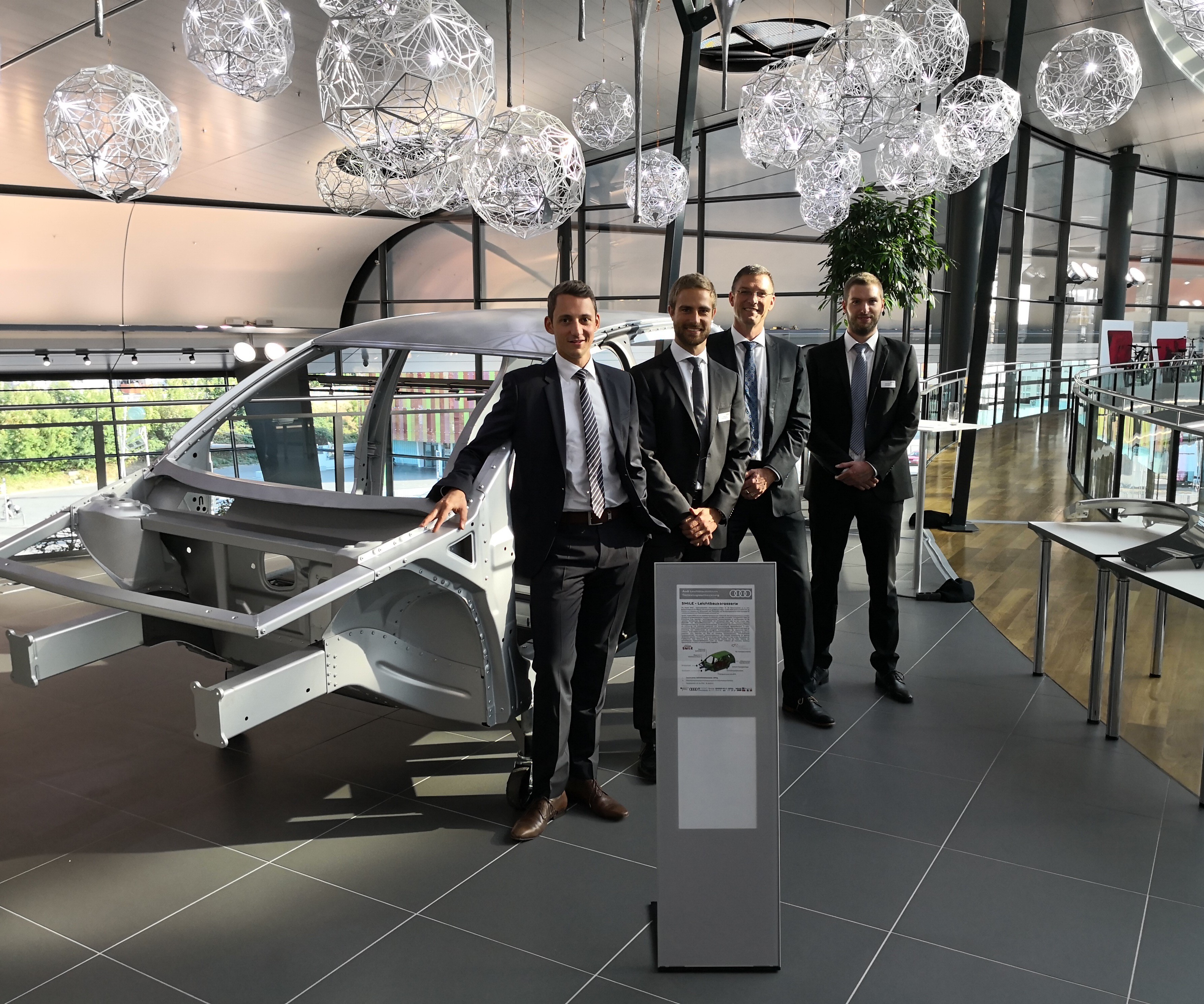
A multiyear, publicly funded research program called System integrated Multi-Material Lightweight Design for E-mobility (SMiLE) took a holistic approach to reducing mass and costs for the entire body-in-white structure (shown here) of a battery-electric vehicle by applying combinations of composites and non-ferrous metals. Some of the F-ICT members who participated in the project are (left to right): Dr.-Ing. Sebastian Baumgärtner, project leader for hybrid thermoplastic floor modules; Tobias Link, research engineer; Prof. Dr. Frank Henning, deputy head of F-ICT; and Felix Behnisch, project leader for thermoset floor modules. Source | Fraunhofer Institute for Chemical Technology.
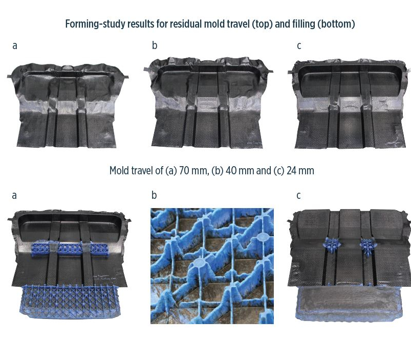
Fig. 1 Forming-Study results for residual mold travel and filling
Extensive simulation work that was subsequently verified by small- and large-part testing was done on all major aspects of the rear floor module’s design, processability, and performance. For example, several different forming studies looked at the impact of mold travel (top) and filling (bottom). Source | Fraunhofer Institute for Chemical Technology
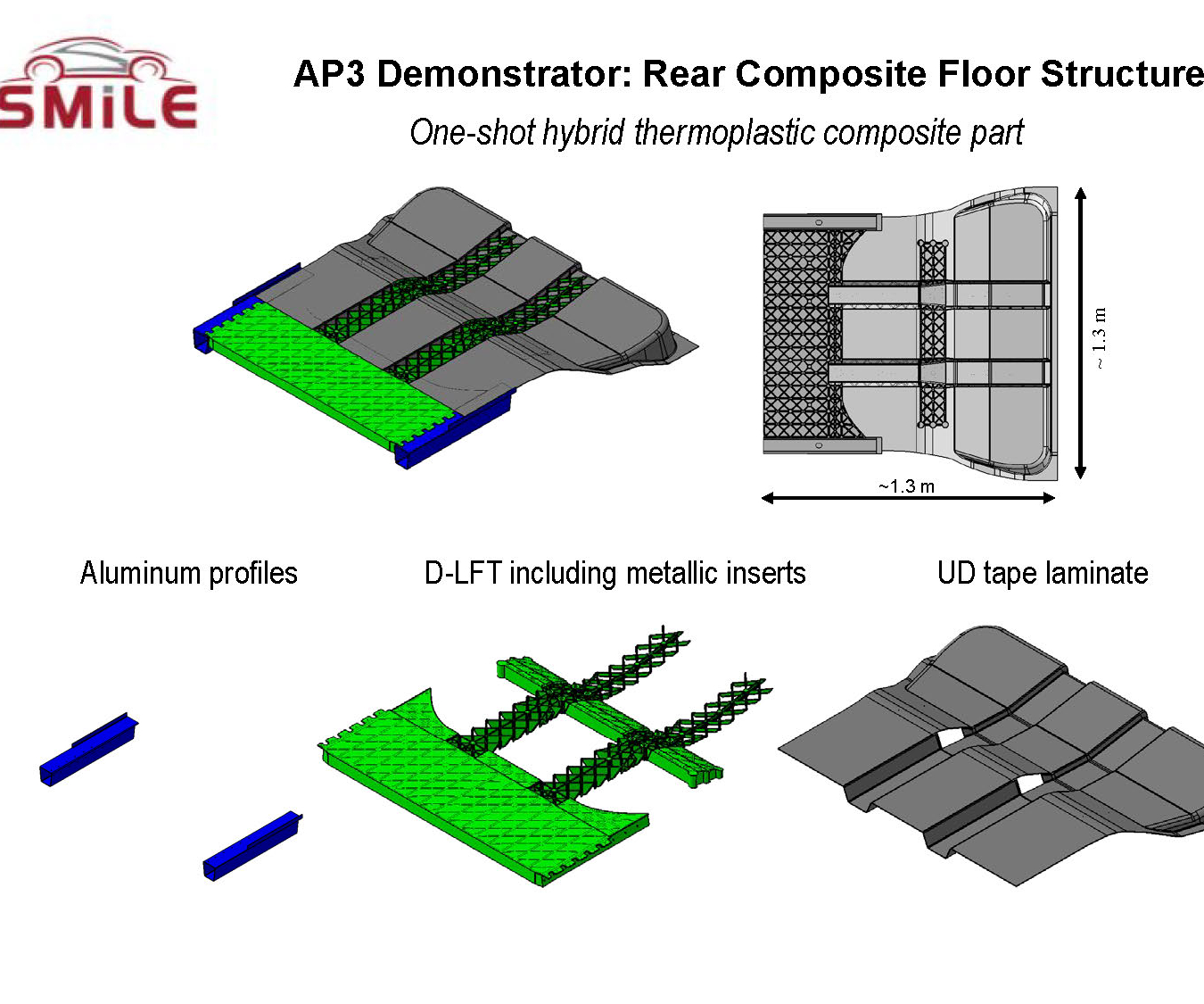
Fig. 2 Rear composite floor structure
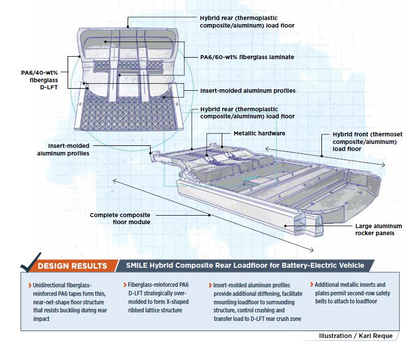
The final rear floor module demonstrator featured a thin-shell, near-net-shape structure produced from UD tapes preconsolidated into a laminate (gray) as well as D-LFT ribs (green) in X-shaped lattice structures with select use of integral metallic inserts and aluminum profiles (blue) on the axial side of the part. D-LFT ribs are 2.5-3.8 cm tall. Source | Fraunhofer Institute for Chemical Technology
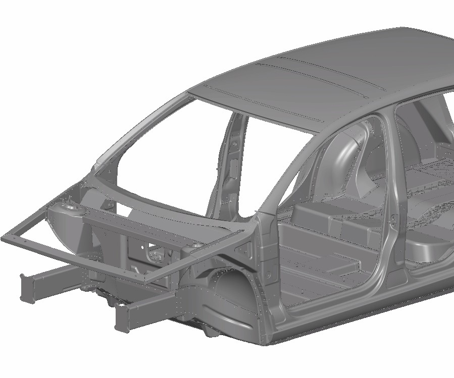
Fig. 3 Reduction in weight for BIW structures
At the conclusion of the SMiLE program, the total mass of the BIW for comparable vehicles was reduced 153.55 kg (42.39%) by using the holistic approach of applying composites and non-ferrous metals where each made sense. Although one project goal had been to reduce the BIW to 200 kg or less, as the project evolved, researchers desired better crash performance (adding composite structure) and needed to address costs (opting to switch from carbon fiber to glass fiber reinforcement for thermoplastic composites in the rear load floor), adding mass. Source | Audi AG
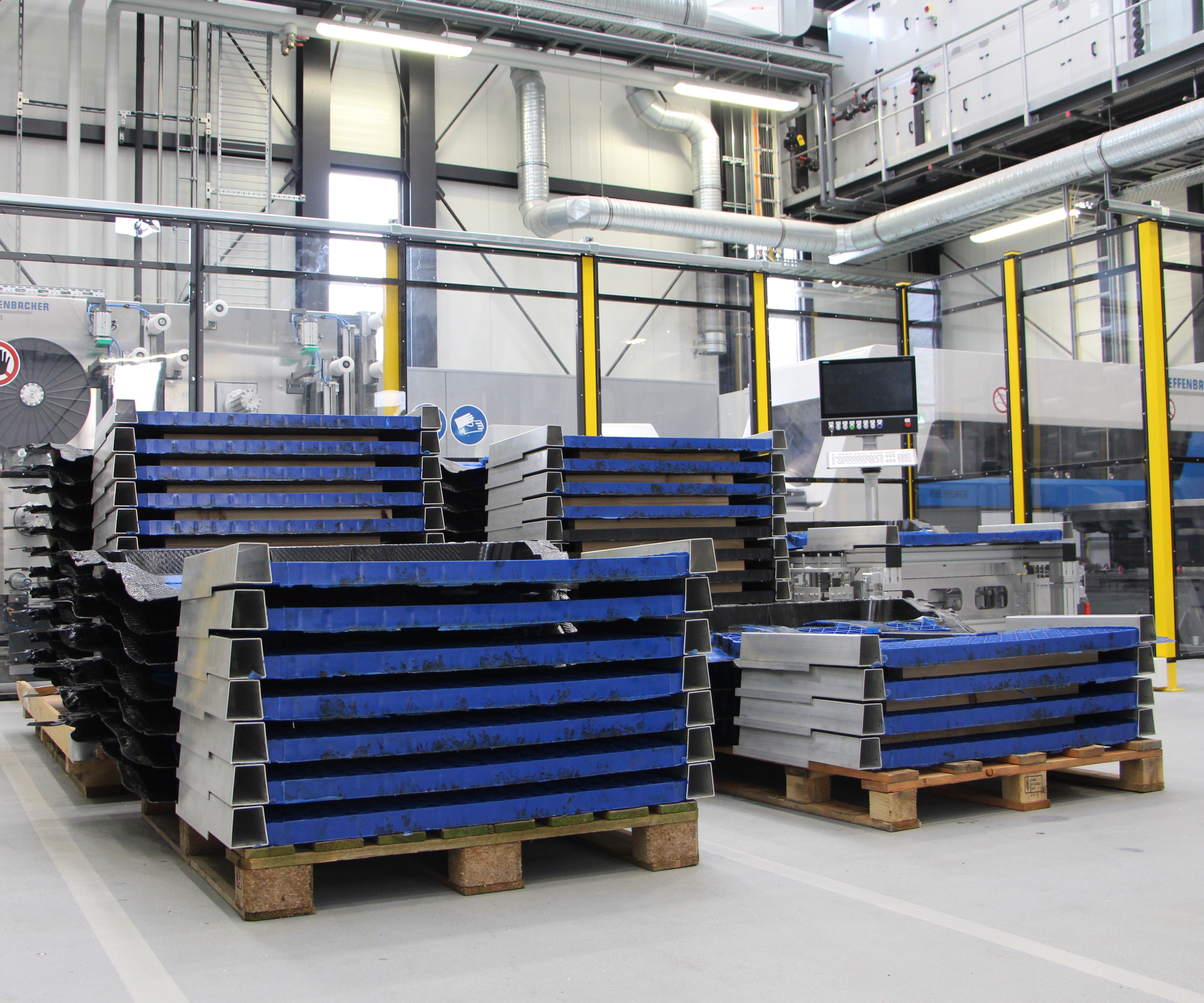
Fig. 4 Molding trials for load floor design
During the final molding trial for the rear thermoplastic composite load floor, more than 100 test parts were produced (shown here). Source | Fraunhofer Institute for Chemical Technology
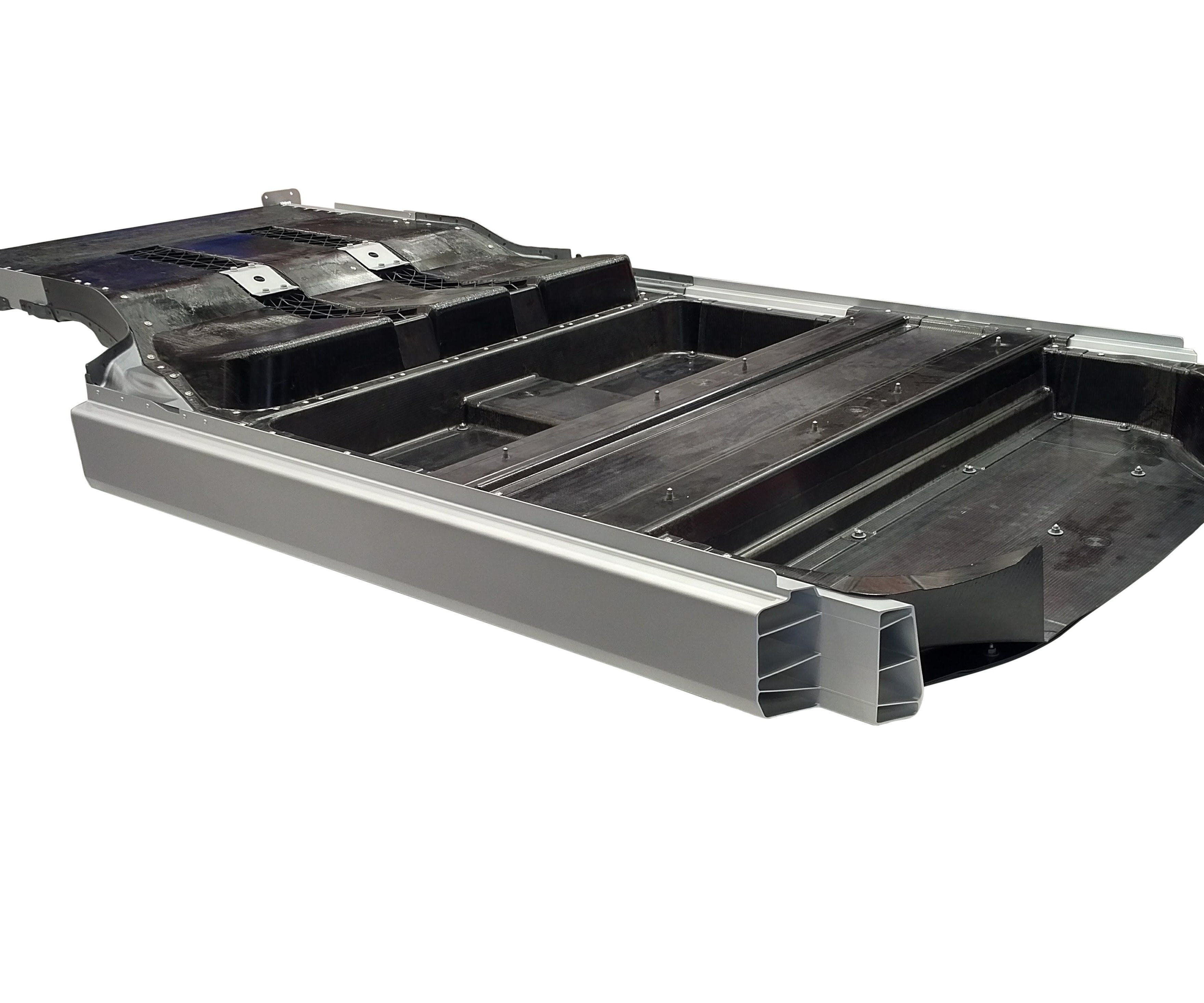
Fig. 5 Combining thermoplastics and thermosets
Some of the test parts produced during the final molding trial for the rear thermoplastic composite load floor were joined with the front thermoset composite load floor and side rockers to produce demonstrator parts (shown here) for further evaluation. Source | Fraunhofer Institute for Chemical Technology


An ambitious multi-year program by Germany’s System integrated Multi-Material Lightweight Design for E-mobility (SMiLE) consortium has developed a demonstrator automotive load floor module that is part of a larger hybrid body-in-white (BIW) structure and that shows great promise for use of composites and non-ferrous metals in a medium-volume production environment. This battery-electric vehicle’s (BEV’s) rear load floor is comprised of two types of thermoplastic composite, plus metallic profiles and inserts. It functions as the floor of the trunk and rear passenger compartment. In turn, it’s adhesively and mechanically joined to a second, hybrid/thermoset composite load floor, which is resin transfer molded (RTM’d) from carbon fiber-reinforced epoxy with metallic inserts and local sandwich structures containing polyurethane-foam cores. This structure is the floor for the front half of the vehicle and holds its batteries. The complete load floor module is bonded and screwed to aluminum rockers/side rails, which are themselves bolted to crossbeams on the vehicle’s aluminum monocoque. The entire load floor module demonstrator was designed to reduce mass and provide significant crash energy absorption for a series-production vehicle with build volumes of 300 cars/day.
Design decisions
Consortium members who worked on the rear load floor included automakers Audi AG (Ingolstadt, Germany—also leader of the entire SMiLE program) and Audi owner Volkswagen AG (Wolfsburg, Germany); Karlsruhe Institute of Technology’s Institute of Vehicle System Technology (KIT-FAST, Karlsruhe, Germany); Fraunhofer Institute for Chemical Technology (F-ICT, Pfitztal, Germany, leader for both front and rear load floor projects), and Fraunhofer Institute for Mechanics of Materials (F-IWM, Freiburg, Germany); thermoplastic composites supplier BASF SE (Ludwigshafen, Germany); machinery OEM Dieffenbacher GmbH Maschinen- und Anlagenbau (Eppingen, Germany), and toolmaker/molder Frimo Group GmbH (Lotte, Germany).


With goals to absorb higher impact energy while reducing mass and cost for both the rear and front load floors as well the larger BIW structure of which they were a part, the decision was made to produce the rear load floor using thermoplastic composites with metallic inserts. The team wanted to add trunk features and second-row seatbelt-attachment structures, but they also wanted to use the load floor to absorb significant crash energies. Normally, carmakers rely primarily on metallic profiles on the sides of metallic load floors to manage rear-crash energies on passenger vehicles. However, given the impact strength of thermoplastic composites, researchers wondered if the entire width and length of a composite load floor could be used to manage crash loads. They also wondered if higher crash energies could be absorbed.
Researchers reviewed common automotive thermoplastic composites. Polypropylene (PP) and polyamide 6 (PA6) matrices were considered but PP was eliminated for temperature reasons since the rear load floor travels with the BIW through the high-temperature electrophoretic coating (e-coat) rust-prevention process. Continuous fiber reinforcement was needed to achieve the highest stiffness and strength, so pretrial work focused on fabric-reinforced organosheet (a form of glass-mat thermoplastic (GMT) composite) and unidirectional (UD) thermoplastic prepregtapes. For many reasons, tapes were selected for further prototyping.
Researchers knew geometry of the rear load floor would be complex. Use of automated tape-laying (ATL) machines — which place UD tapes in any orientation and make windows/holes with less material than organosheet — would reduce scrap, mass and cost, and permit the most efficient use of fibers locally and globally across the part. Also, since fibers placed via ATL lie flat and parallel in each layer of the ply stack and are not woven like fabrics, there is no undulation and consequent loss of stiffness and strength.
UD tapes do have limitations, however: They are relatively expensive and have poor drapeability with almost no flow, making it difficult to fill complex geometries. These issues were overcome by selectively using discontinuous/chopped direct-long fiber thermoplastic (D-LFT) composites, which are flowable, allow high levels of functional integration/parts consolidation and are far easier to form into complex ribs without fiber bridging, yet can absorb significant crash energy. With D-LFT, it is also easier to insert metallic attachments, especially if inserts are predrilled so holes permit composite to flow through and around the metal, creating a strong bond via mechanical interlocking. Further, D-LFT is less costly than tapes or organosheet and far easier to mold in thick sections. Compounded at press side, D-LFT simplifies materials inventory management and offers high flexibility on development programs to quickly change material features — fiber length and type, fiber-volume-fraction (FVF) and matrix — as parts are made and evaluated. During production, material/process settings are controllable to achieve high levels of repeatability and reproducibility (R&R), which is why automotive has used the process for medium-to-high-volume production for almost two decades.
Because researchers wanted to keep the rear load floor thin and light and able to resist buckling while absorbing high impact loads, they conducted simulations and initial development through small-part testing with glass- and carbon fiber-reinforced tapes and D-LFT at different fiber-weight fractions (FWFs) to evaluate mechanical performance vs. filling behavior. Although carbon composites produced thinner, lighter, stiffer structures than did glass, because cost also was a concern and the front load floor already used carbon fiber reinforcement, researchers selected glass to reinforce the rear load floor during scale-up to full-size parts. Ultramid B3K PA6 D-LFT with 40-wt% fiberglass and eight layers of Ultratape B3WG12 PA6 with 60-wt% fiberglass, both from BASF, were used.
After much simulation work, the 1.3-by-1.3m rear load floor’s final design comprises a thin-shell, near-net-shape structure produced from UD tapes preconsolidated into a laminate interwoven with a thicker D-LFT crush zone (see Fig. 2). Large corrugations, also made of UD tape , with deep troughs (50 mm high by 115 mm wide) were molded along the part’s longitudinal axis for high stiffness at low mass and thickness. Additionally, two windows were formed during tape layup to allow D-LFT to penetrate through the laminate to where it was needed. Because deep corrugations are difficult to form in large laminates, it was necessary to modify both molding process and tool to produce good parts (see “How Research on an Automotive Floor Module Drove Development of a New D-LFT/Compression Molding Subprocess”). These corrugations, in combination with two charges of D-LFT that formed complex ribs in X-shaped lattice structures, generate a high moment of inertia for the area, increasing part stiffness in the thin, lightweight design while avoiding buckling in a crash. D-LFT lattices at the part’s rear formed a crush zone to absorb energy in rear crashes. Aluminum profiles were integrally molded on axial sides of the load floor and bonded to D-LFT and laminate via special surface treatments as well as holes that provide interlocking. These profiles were carefully designed to further increase part stiffness, provide good buckling behavior and transfer force into the D-LFT crush zone during a crash. They also provide attachment points for direct mounting of the rear load floor to surrounding metallic structures. Additional metallic inserts, also integrally molded into the structure, provided direct mounting for seatbelt locks.
Successful implementation
Simulation work as well as small- and large-part testing verified that the entire hybrid rear load floor could be used to manage crash loads. Further assessment revealed that this technology should be as safe as conventional metallic structures.
One larger project goal — reducing total BIW mass to 200 kg — was theoretically met during simulation and small-part development. However, as the project evolved, better crash performance was desired, which required adding mass to composite structures. In addition, cost considerations led to a switch from carbon fiber to glass fiber reinforcement for the rear load floor. The resulting rear load floor with inserts weighs 32.9 kg, while the front load floor (with inserts but without batteries) weighs 12.1 kg. For final test parts, the mass target was missed by just 4.3% to achieve higher safety and lower costs. The SMiLE BIW also would be more costly than conventional metallic systems owing to the intensive use of carbon fiber reinforcement in the front load floor.
The rear load floor project led to F-ICT’s development of a D-LFT/compression subprocess called local advanced tailored LFT, which selectively applies D-LFT material to largely UD-tape structures to produce locally complex geometries (like ribs) that cannot be made with tapes. Another F-ICT technology developed before SMiLE but used on the project is a method to rapidly heat and consolidate thermoplastic tapes via radiation-induced vacuum-consolidation, a technology now commercially available from Dieffenbacher on a machine called Fibercon.
Remarkably, the experimental process and highly complex tool produced by Frimo worked from the start and more than 100 demonstrator parts were produced for subsequent testing and demonstration. Although the team designed the molding process to be done in a single step, Dr.-Ing. Sebastian Baumgärtner, F-ICT team leader for thermoplastic processing and leader of the rear load floor project, believes that in a production environment it would be more efficient to form this complex part in two steps, with laminate preforming done in a separate tool. “We opted to try the harder one-step process first and it worked well,” Baumgärtner explains. “However, the tool was very complex and process control was not so easy. If the laminate got too hot in spots, it had a very-strong interaction with the LFT strands. To ensure good repeatability during production, it would be better to simplify things and choose a two-step process, which would be more robust.” Still, given the large size of this composite part and the complex process used to form it, the team was very pleased with the end results. “We demonstrated that we could produce an innovative and economic part that was weight and performance optimized and featured high functional integration using commercial technology,” he adds.
The complete load floor won the 2018 CCE-JEC Innovation Award in China and the German government recognized the larger SMiLE program as a Lighthouse project, meaning the technology will be important for use in future mobility design. The team is in discussion about next steps.


Related Content

Materials & Processes: Resin matrices for composites
The matrix binds the fiber reinforcement, gives the composite component its shape and determines its surface quality. A composite matrix may be a polymer, ceramic, metal or carbon. Here’s a guide to selection.
Read More
PEEK vs. PEKK vs. PAEK and continuous compression molding
Suppliers of thermoplastics and carbon fiber chime in regarding PEEK vs. PEKK, and now PAEK, as well as in-situ consolidation — the supply chain for thermoplastic tape composites continues to evolve.
Read More
TU Munich develops cuboidal conformable tanks using carbon fiber composites for increased hydrogen storage
Flat tank enabling standard platform for BEV and FCEV uses thermoplastic and thermoset composites, overwrapped skeleton design in pursuit of 25% more H2 storage.
Read More
Materials & Processes: Composites fibers and resins
Compared to legacy materials like steel, aluminum, iron and titanium, composites are still coming of age, and only just now are being better understood by design and manufacturing engineers. However, composites’ physical properties — combined with unbeatable light weight — make them undeniably attractive.
Read MoreRead Next

Composites end markets: Energy (2024)
Composites are used widely in oil/gas, wind and other renewable energy applications. Despite market challenges, growth potential and innovation for composites continue.
Read More
From the CW Archives: The tale of the thermoplastic cryotank
In 2006, guest columnist Bob Hartunian related the story of his efforts two decades prior, while at McDonnell Douglas, to develop a thermoplastic composite crytank for hydrogen storage. He learned a lot of lessons.
Read More
CW’s 2024 Top Shops survey offers new approach to benchmarking
Respondents that complete the survey by April 30, 2024, have the chance to be recognized as an honoree.
Read More