
Continuous tapes, D-LFT meet up in new compression molding process
Design research for an automotive load floor module drove development of a new compression molding process for direct-long-fiber thermoplastic (D-LFT) composites.

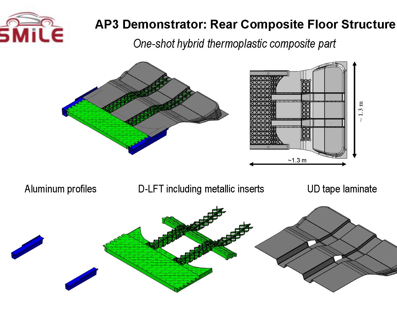
A multiyear German research program looked for ways to reduce the mass of a battery-electric vehicle’s body-in-white structure through the most efficient use of composites and non-ferrous metals. One aspect of the program looked at ways to produce a rear composite loadfloor (in both UD tape laminates with selectively overmolded D-LFT ribs, metallic inserts and aluminum profiles). To produce the part, a new D-LFT/compression molding subprocess and a very complex tool had to be developed. Additionally, a method that had been developed earlier to rapidly heat and consolidate the thermoplastic composite tape stack into a tailored-blank laminate was used to produce this novel demonstrator part. Source | Fraunhofer Institute for Chemical Technology
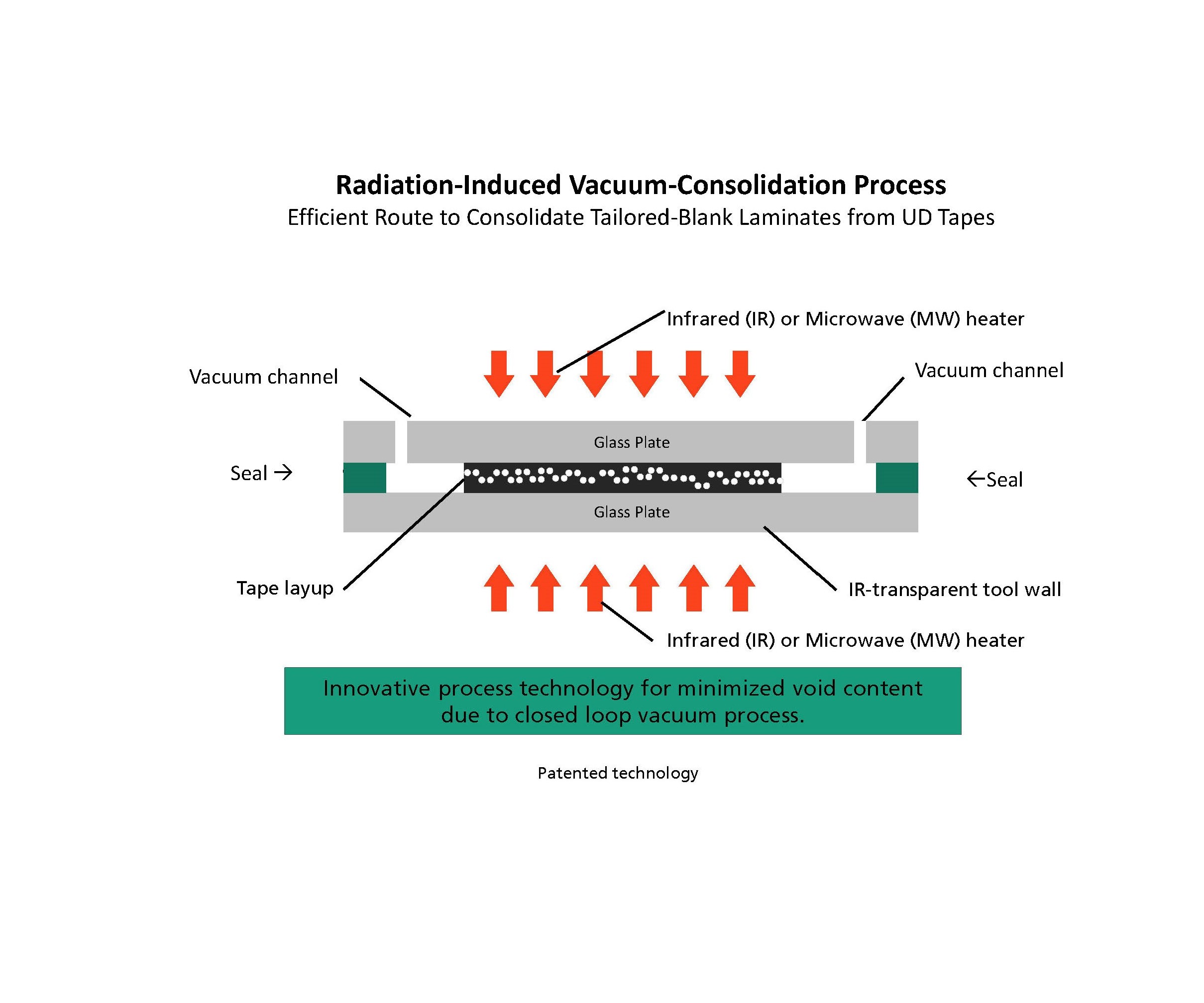
Radiaton-induced vacuum-consolidation is a technology developed by Fraunhofer ICT before the SMiLE project. It was used to consolidate the UD-tape ply stack into a tailored-blank laminate for the rear loadfloor. The technology has since been commercialized by Dieffenbacher into a machine called Fibercon. Source | Fraunhofer Institute for Chemical Technology
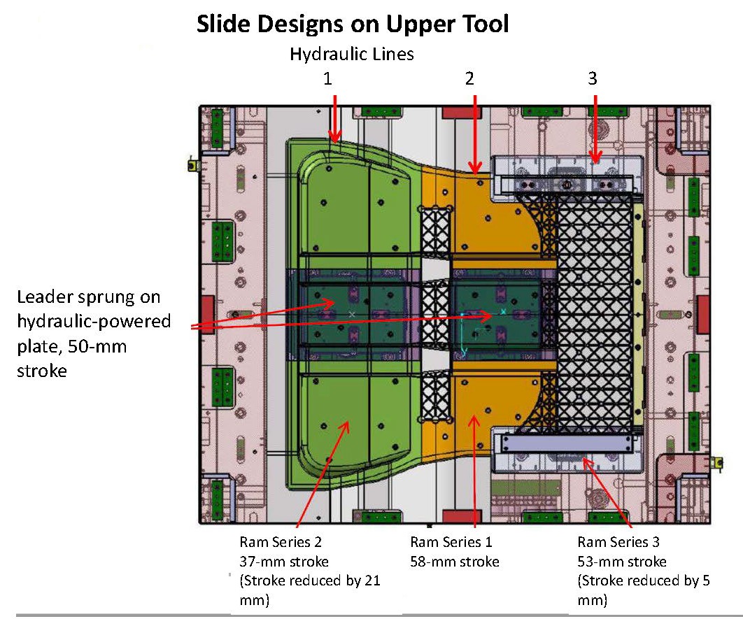
To implement the sequential forming process to preform the tape-laminate shell for the loadfloor prior to press closure, it was necessary to build a tool with six displaceable cavities using four slides. The slides activate in sequence to shape the laminate, including deep corrugations along the part’s longitudinal axis (top and bottom). Source | Fraunhofer Institute for Chemical Technology


A multiyear, publicly funded research program, overseen by Germany’s Federal Ministry of Education and Research (BMBF) and called System integrated Multi-Material Lightweight Design for E-mobility (SMiLE), combined composites and non-ferrous metals to reduce mass and costs for the entire body-in-white (BIW) structure of a battery-electric vehicle (BEV). The rear floor module was designed using two types of thermoplastic composites plus metallic profiles and inserts. (Learn more in CW’s December 2018 Focus on Design.) In order to rapidly and cost-efficiently produce this load floor, a new one-step compression molding subprocess was developed and a new technology to rapidly heat and consolidate thermoplastic tapes was used.


UD tape + D-LFT
The hybrid-composite rear load floor uses unidirectional (UD) thermoplastic tapes plus direct-long-fiber thermoplastic (D-LFT) composites. Thermoplastic tapes provided high stiffness/strength in a thin, lightweight structure capable of resisting high buckling loads in a crash; D-LFT provided the ability to form complex geometries, functional integration/parts consolidation and the ability to insert-mold metallic attachment features. Ultramid B3K polyamide 6 (PA6) D-LFT with 40-wt% fiberglass reinforcement and eight layers of Ultratape B3WG12 PA6 with 60-wt% fiberglass loading, both from BASF SE (Ludwigshafen, Germany), were used.
Although D-LFT can be injection or compression molded, and tape laminates can be injection overmolded, both materials are commonly compression molded — a well-understood automotive process with sufficient installed capacity locally and globally to support the SMiLE program’s target of 300 vehicles/day.
UD tapes and D-LFT often are combined in the same part in one of two ways: Either tapes are selectively added to load paths in predominantly D-LFT structures that need better mechanical properties — a technique called tailored D-LFT, which also can use continuous fiber rovings instead of or in combination with tapes — or tapes and D-LFT are used to cover opposite sides of a part. In the first technique, it’s easy for flowable D-LFT to push thin tapes out of position during overmolding, necessitating use of clips or other hardware inside the tool to maintain tape position. While it’s less costly to selectively use tapes in predominantly D-LFT structures, such parts are not as strong or light as those that use a higher ratio of tapes to D-LFT. With the second technique, applying tapes and D-LFT on opposite sides of a part, better functional integration/parts consolidation is achieved on the D-LFT side, and higher stiffness/strength is achieved on the UD tape side (see “Hybrid thermoplastic molding: Toughening automotive composites”), but the resulting structure still is relatively heavy and not as stiff and strong as it could be.
Given the safety-critical nature of vehicle load floors, and SMiLE researchers’ desire to use the entire thermoplastic-composite rear load floor to absorb crash energies (not just with metallic profiles mounted to axial sides of conventional all-metallic or the new hybrid-composite load floor), it was important to make the rear load floor as stiff and strong as possible. Since researchers needed to reduce both weight and cost to hit project targets, wanted to keep the load floor thin while avoiding buckling during impact, and also desired to add functionality in key locations (e.g., attachment points for second-row seatbelts), they developed a new D-LFT/compression molding subprocess where most of the load floor was thermoplastic tape (preconsolidated into a laminate prior to molding), with D-LFT selectively applied only where ribs and complex geometries were needed, but impossible to form with tape laminates alone.
The team also decided to try to produce the 1.3-by-1.3m rear load floor in a single step inside the compression-molding press. To realize all of these goals, the team needed a combination of interesting and innovative tooling and a sequential forming process.
Local advanced tailored LFT
The rear load floor’s final design is a thin-shell, near-net-shape structure produced via UD tapes preconsolidated into a laminate. Large corrugations are included along the part’s longitudinal axis for high strength at low mass and thickness. However, researchers knew these corrugations would be difficult to mold in the large laminate. To ensure good draping, simulation was used to design the mold to verify reproducible forming of the corrugations (50 mm high by 115 mm wide) and to minimize wrinkling. If they got it wrong and the corrugations did not mold correctly, the laminate could wrinkle or shift out of plane, and bond strength with the D-LFT would be poor. Virtual prototyping predicted that the best forming sequence was from the inside/center outward toward the sides, similar to what is typically done with hand layup. The only way a sequential forming process could be done in one molding step (where the laminate wasn’t preformed outside of the main press) was to use tooling action (slides).
Slides are common in very complex injection molding tools. While they are not unheard of in compression molding, they’re less common and tend to be far less complex when they are used. Researchers designed the tool with six displaceable cavities (using four slides) to form corrugations and other structures in the laminate, rather than just overmolding them in D-LFT, which otherwise would have added significant mass and thickness to the part.
Earlier work on interfacial strength at the laminate/D-LFT rib joints had shown superior bond strength was achieved if, prior to overmolding, the laminate maintained a temperature of at least 130°C — below the melting point of the PA6 matrix — and D-LFT was delivered to the tool at 280°C, above PA6’s melting point. To keep the laminate from cooling too quickly against the tool before D-LFT charges were placed, researchers laid it on fully extended ejector pins on the cavity side of the tool. As two D-LFT charges were delivered, the ejector pins lowered and the mold started to close. Next, the four slides — three of which operated using the machine’s hydraulic system, with the fourth operated via spring action — extended in sequence to form the laminate, including its deep corrugations. Once the press was fully closed, the D-LFT rib structures (in a complex X-shaped lattice) were formed. Researchers called this sequential forming technique local advanced tailored LFT.
In another departure from conventional compression tool design, the mold was constructed with shear edges only in sections where D-LFT flowed to a part edge in order to mold select charges of flowable D-LFT against the unflowable tape laminate that made up the bulk of the structure.
Radiation-induced vacuum consolidation technology
An important process step to ensure reproducible forming behavior and high mechanical performance in the final part is tape consolidation. By rapidly heating thermoplastic tape stacks just prior to forming, voids are eliminated within and between plies and excellent consolidation/fiber impregnation is achieved. To keep this from being the rate-limiting step, the process was matched to the speed of automated thermoplastic tape layup — a Fiberforge RELAY tape-laying machine from Dieffenbacher GmbH (Eppingen, Germany) was used — as well as molding cycles on the compression press, a 3,600-ton Compress Plus DCP-G 3600/3200 AS press, also from Dieffenbacher, used to form the rear load floor.
Before SMiLE, Fraunhofer Institute for Chemical Technology (F-ICT, Pfitztal, Germany) — which led development of the front and rear load floors in the larger SMiLE program, and also helped develop the local advanced tailored LFT sequential-molding process with other program partners — had developed an innovative process called radiation-induced vacuum-consolidation technology for rapidly consolidating UD-tape stacks into laminates that was subsequently applied to produce the rear thermoplastic load floor. Dieffenbacher has since commercialized the with a machine called Fibercon. The process was designed to heal impregnation defects in tapes, which allows less costly tapes to be used while minimizing voids in final parts. It involves applying large amounts of infrared (IR) heat to the top and bottom layers of the ply stack (transmission is through IR-transparent glass plates on which the ply stack rests) while holding the entire stack under vacuum. This removes air, flows the resin and fills gaps in and between tapes. The heat is only applied for a short duration, enabling the tapes to bond to each other and solidify quickly without moving the ply stack out of place. It also was designed for fast, homogeneous consolidation of the ply stack into a laminate with high and consistent properties throughout, making forming behavior reproducible and easier to simulate, and ensuring high mechanical properties in the final part. Another concern was how to maintain heat in the consolidated laminate en route to the press, to ensure good molding properties without wasting energy to reheat the laminate before forming. Once consolidated, the now-fused laminate is quickly reheated prior to being removed from the machine and rapidly moved to the press for forming.
Final process sequence
The final process sequence for the rear load floor took place on four pieces of equipment, three of which operate simultaneously in the work cell.
First, tapes were automatically laid up using orientations determined by simulation via a Fiberforge RELAY tape-laying system. An indexing table makes it easy to lay up tape in virtually any orientation on each layer of the ply stack. Individual tapes on each layer are lightly tacked to the layer below via spot welding, and the bottom layer is held in place during layup via vacuum. Since tape is individually cut for each piece of each layer, there is minimal waste and minimal post-mold trimming is needed. The system also can lay up holes/windows in the stack by trimming tape edges prior to tackdown, which reduces post-mold trimming and further reduces scrap and costs.
Next, the ply stack was moved from the Fiberforge RELAY machine to the Fibercon machine and set between that unit’s glass plates. As the unit closed, a vacuum was pulled on the stack and IR heat was projected for a short time through the top and bottom plates, rapidly heating the PA6 matrix above its melting point (~230°C), flowing resin and removing voids. The laminate was then cooled below the resin’s crystallization temperature (~180°C), consolidating individual tapes into a single laminate.
In the now-open compression press, which had just ejected its previous part, ejector pins were left out and researchers manually loaded two aluminum profiles and several metallic inserts into the tool’s upper/core side while waiting for the next round of materials to arrive.
The still-hot laminate in the Fibercon was again heated above PA6’s melting point, the unit was opened and the laminate was transferred to the open compression press. Since air is a poorer thermal conductor than steel, the laminate was then laid on fully extended ejector pins on the cavity side of the tool to help hold heat in the laminate prior to arrival of the D-LFT charges.
While tapes were being laid up and consolidated, nearby D-LFT material was being compounded using two extruders (the In-Line Compounder system from Dieffenbacher). The first extruder combined resin and additives while the second chopped fiber to desired length and then combined resin/additives with fiber to produce fully mixed, pre-weighed charges of hot D-LFT that then were delivered to the compression press. In the case of the load floor, two D-LFT charges were placed on the laminate as it was lowered to the tool by retracting ejector pins.
With the hotter D-LFT charges sitting on the cooler laminate, the press started to close as the four slides deployed in sequence to pre-shape the laminate prior to full tool closure. Sequential application of the slides prevented wrinkling of the laminate as 3D features, including corrugations, formed. Once the upper tool closed, the tape laminate was fully formed and the hot D-LFT charges were molded at 1,430 MT into ribbed-lattice structures. The complete part, with fully integrated metallic inserts, was then ejected after the press opened.
In a production environment, all materials handling would be done using gantry robots equipped with needle grippers, but for the SMiLE research program it was done by hand. For the research program, the total molding cycle was 240 seconds, slowed by molding the load floor’s thick ribs. Researchers believe that in a production environment they could get cycle times below 100 seconds with further tooling modifications, and that they could drive them even lower if the laminate was preformed prior to placement in the press.


.jpg;maxWidth=300;quality=90;format=webp)


Related Content

PEEK vs. PEKK vs. PAEK and continuous compression molding
Suppliers of thermoplastics and carbon fiber chime in regarding PEEK vs. PEKK, and now PAEK, as well as in-situ consolidation — the supply chain for thermoplastic tape composites continues to evolve.
Read More
RUAG rebrands as Beyond Gravity, boosts CFRP satellite dispenser capacity
NEW smart factory in Linköping will double production and use sensors, data analytics for real-time quality control — CW talks with Holger Wentscher, Beyond Gravity’s head of launcher programs.
Read More
Materials & Processes: Tooling for composites
Composite parts are formed in molds, also known as tools. Tools can be made from virtually any material. The material type, shape and complexity depend upon the part and length of production run. Here's a short summary of the issues involved in electing and making tools.
Read More
The state of recycled carbon fiber
As the need for carbon fiber rises, can recycling fill the gap?
Read MoreRead Next

Hybrid thermoplastic molding: Toughening automotive composites
Tailored D-LFT with continuous and discontinuous glass offers best combination of strength, moldability.
Read More
From the CW Archives: The tale of the thermoplastic cryotank
In 2006, guest columnist Bob Hartunian related the story of his efforts two decades prior, while at McDonnell Douglas, to develop a thermoplastic composite crytank for hydrogen storage. He learned a lot of lessons.
Read More
CW’s 2024 Top Shops survey offers new approach to benchmarking
Respondents that complete the survey by April 30, 2024, have the chance to be recognized as an honoree.
Read More