
Automated Preforming, Part 3: Quilted Stratum Process
CW’s tour of Cetim and the QSP line which preforms multi-thickness thermoplastic materials in 40-90 seconds for composite parts with cycle times of 1-2 minutes.


This is part three of a seven-part series about preforming. For more on this series, click the links below:
part one, part two, part four, part five, part six, part seven.


Also, don’t miss the printed version of this series:
Preforming Goes Industrial, Part 1 and Part 2.
In this blog, I describe the Quilted Stratum Process (QSP) based on my tour of the pilot production line at Cetim (Nantes, France) and also include a brief section at the end on Cetim's 3D thermoplastic filament winding technology for Class V pressure vessels, referred to as Spide TP.
When development of QSP began in 2013, the goal was to produce load- and weight-optimized multi-oriented, multi-thickness composite parts in one minute. Faster speed would be possible by using thermoplastics vs. thermosets, and would also eliminate wet, chemical processes. Fiber-reinforced thermoplastic tapes and organosheets could be sourced easily or produced in-line and would be easy to handle. They could also be ultrasonically tacked together to produce preforms and then thermoformed very quickly to produce parts with integrated inserts and overmolded plastic ribs, bosses, etc.
“Our objectives were to reduce waste and weight and to produce optimized, integrated parts at a competitive cost,” says Franck Bordellier, lead QSP development engineer at Cetim, an engineering and advanced manufacturing R&T organization.
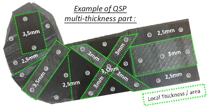
“Quilted” in the process name refers to the precut patches of thermoplastic (TP) tape, while “Stratum” indicates their orientation and layering—putting the right material in the right place—to produce net shape preforms and parts. “We also wanted to integrate molded-in holes and metallic inserts in order to eliminate secondary machining and resulting quality issues like burring,” Bordellier adds.
A QSP pilot production line was completed at Cetim in 2015. With a reported patch preform rate of 5 kg/min, the line is comprised of different modules including:
- TP tape pultrusion
- Patch cutting
- Laying and assembly of tapes into preforms
- Preheating preforms and press molding plus overmolding into parts.
Cetim’s key partners in developing QSP include composites industry press and automated equipment supplier Pinette Emidecau Industries (PEI, Chalon sur Saone, France), tooling specialist Compose (Bellignat, France), thermoplastic composites expert Loiretech (Mauves sur Loire, France), which supplied the preform heating system, and local government Region Pays de Loire.
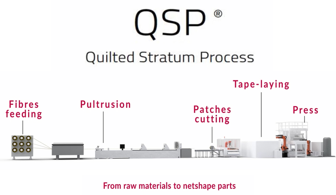
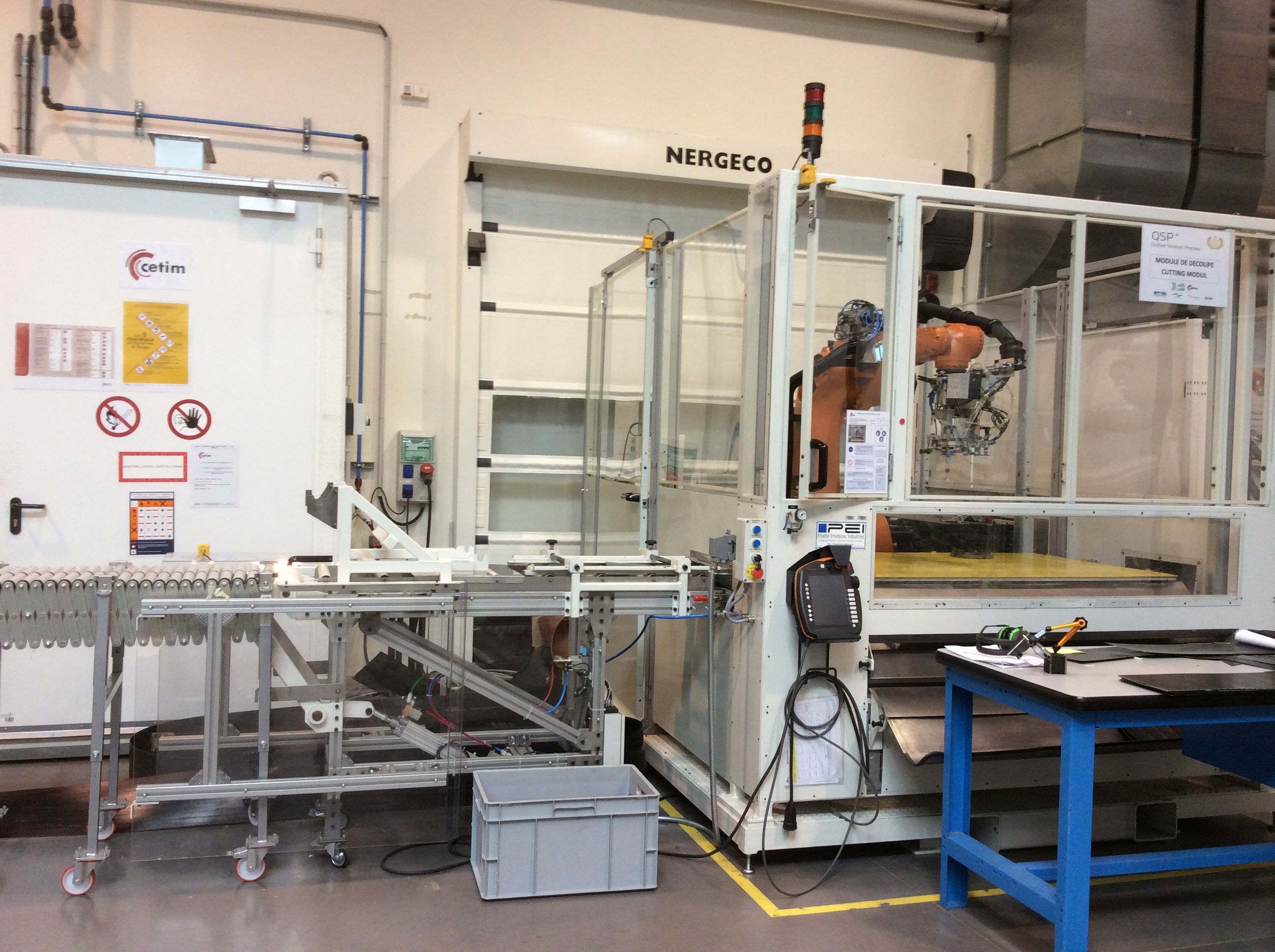
Comprised of multiple different modules, the QSP production line inputs raw materials (fibers, polymers) and outputs net shape thermoplastic composite parts in minutes. |
QSP development was led by the Cetim composites R&D facility in Nantes, with support from composites industry suppliers (Pinette Emidecau, Compose and Loiretech) and various government organizations, including the local Région Pays de Loire. |
SOURCE: Cetim
TP Tape Pultrusion
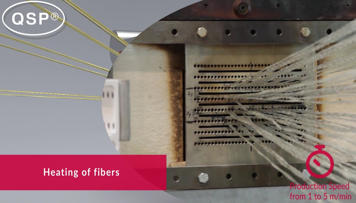
“We have developed thermoplastic pultrusion to provide tapes at the right thickness and width for QSP,” Bordellier explains. The line can pultrude glass or carbon unidirectional (UD) tape at 0.6-3.0 mm thickness and 100-300 mm width. The width being made during CW’s tour was 230 mm. “Our goal is not thin tape but to have thick tapes and profiles with built-in reinforcements,” says Bordellier. “With thin tapes, you need 3-4 layers in the preform. We’d rather have these already plied in the tape.”
He continues, “This is our solution compared to organosheet, which is too high in cost for high-volume parts. The goal is to get tape at a cost of 3 euro per kilogram. Pultrusion can reduce cost because it is a continuous process. Organosheet is 7 euro per kilogram for glass fiber-reinforced polyamide (GF/PA). If we run the line at 3 m/min, we can beat this.”
|

|

Continuous thermoplastic pultrusion process.
SOURCE: Cetim.
Cetim explored several options for how to impregnate UD fibers with a TP matrix:
- Wet process using fluid (melted) polymers;
- Commingled materials (depends on the quality of TP dispersion with fibers);
- Reaction monomers/polymers like caprolactam, laurolactam or Elium.
NOTE:
Commingled fibers/yarns can be made with powdered thermoplastic or by twisting together thermoplastic and reinforcing fibers. Coats Group (Stockley Park, UK and Marion, NC) and Concordia Fibers (Coventry, RI) are two suppliers of commingled products.Caprolactam and laurolactam (linked article, see 5th picture titled Step 1) are monomers with water-like viscosity which polymerize to form Nylon 6 and Nylon 12, respectively. Arkema’s Elium acrylic resin has been designed with low viscosity for processing like a thermoset while providing thermoformability and recyclability like a thermoplastic.
Bordellier explains that viscosity is typically 1 mPa-s for thermosets and 300-500 mPa-s for thermoplastics. (Note that 1 mPa-s = 1 centipoise, cP.) “We need viscosity between 1 and 20 mPa-s, with a maximum of 50 mPa-s,” he adds. Cetim’s pultrusion line is currently using Evolite, a high-flow thermoplastic from Solvay. “We are trialing new Evolite materials and have done a lot of tests with Solvay in collaborative projects. Right now our goal is to improve the speed of the line and perhaps to reduce tooling friction during molding.”
Bordellier stresses that QSP is not a process restricted to UD tapes, but readily accommodates a variety of materials, such as woven fabric-reinforced organosheets. However, UD tapes are an efficient means to tailor preforms for highly optimized, high-performance parts.
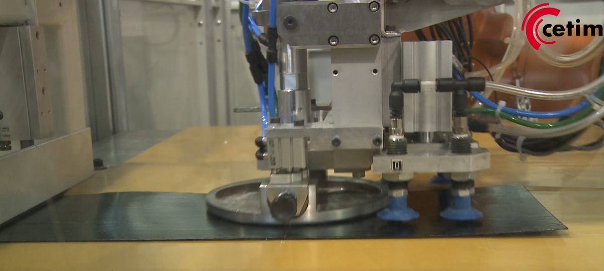
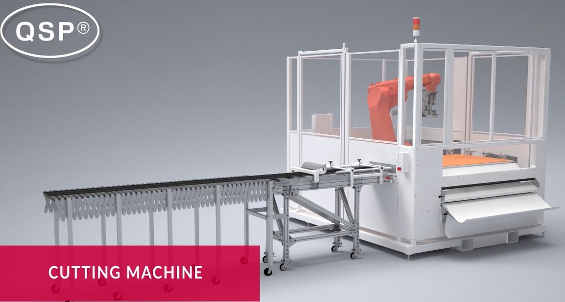
Cutting TP Patches
Continuous pultruded tape feeds into the patch cutting module. “We don’t wind the tape onto a bobbin but instead feed it directly and cut while flat,” says Bordellier. “After you have cut all of the tape patches needed, these are fed into the preform assembly module.” He notes that Pinette Emidecau supplied the cutting module cell.
|
|
|
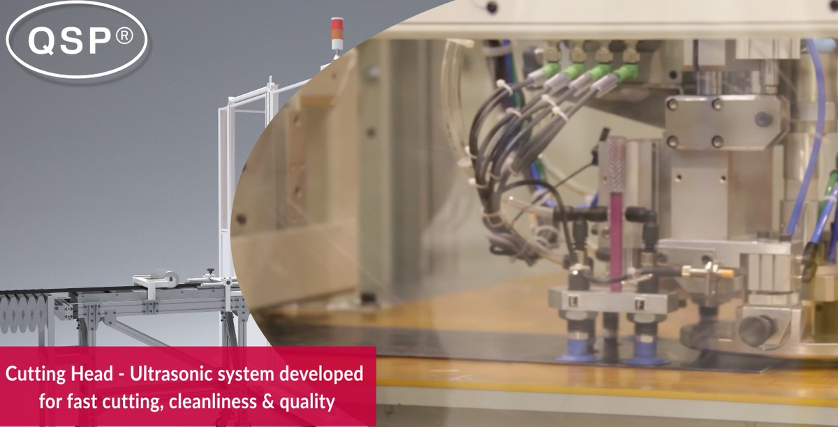
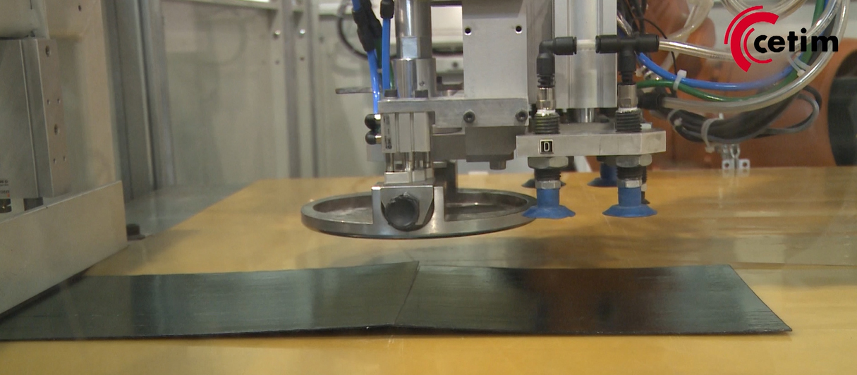
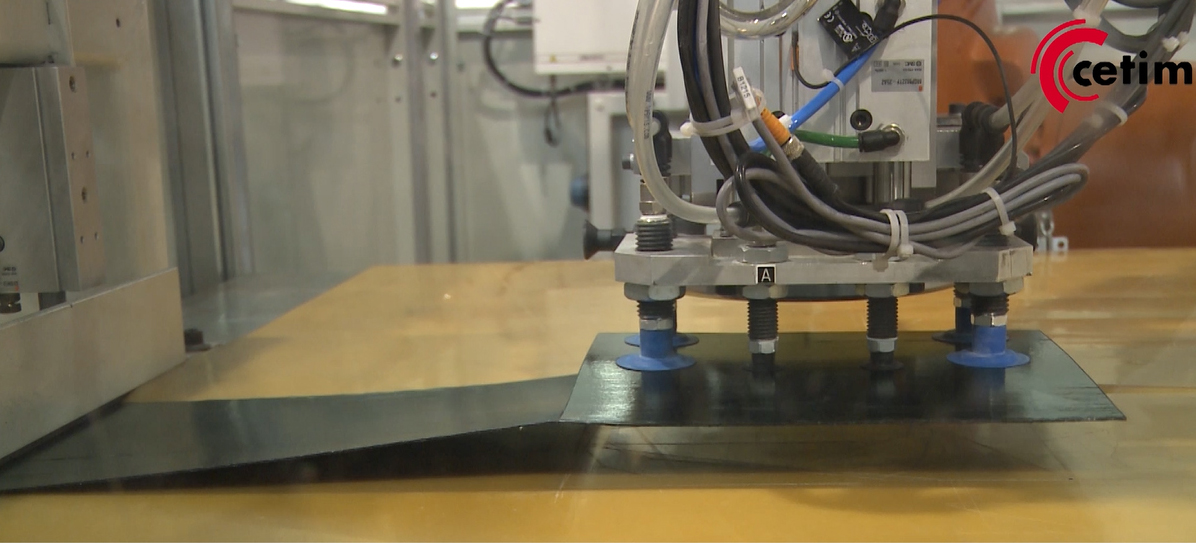
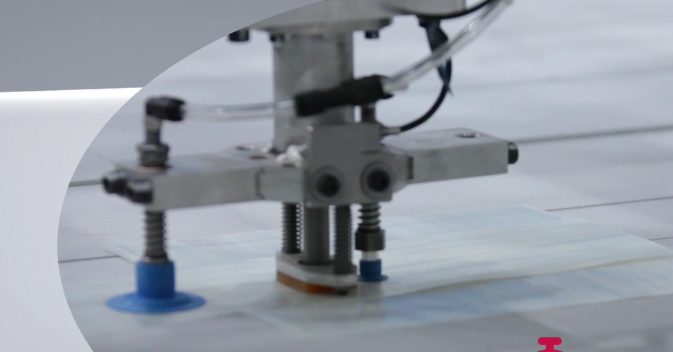
The QSP cutting module features a robotic arm with ultrasonic cutter and grippers for fast, clean, high-quality cuts and easy handling of incoming tape and transfer of cut patches. SOURCE: Cetim.
“We tested waterjet and laser, but these require subsequent drying and cleaning of the parts.” Ultrasonic cutting was chosen instead, using technology developed by Sonimat (Carquefou, France). “It is very fast, greater than 400 mm/s,” Bordellier notes, “but also clean.” He acknowledges there are some limitations regarding thickness, “Up to 1.5 mm is fine, but over that requires several cuts, which then slows the process.”
The robotic arm in the cutting module is equipped with both vacuum grippers and ultrasonic cutter. It pulls in tape, cuts at whatever angle required and then picks up the patch and deposits it into an outfeed slot for subsequent transfer into the preform assembly module or storage for later processing.
Preform Assembly
The preform assembly module is actually what the QSP initially described, with patches laid and built up into variable-thickness preforms. This part of the pilot production line, though fully covered by patents, is kept hidden within a white enclosure. (The photos below are via QSP videos.)

|
|
|

|
The QSP preform assembly module places and ultrasonically welds patches to create multi-thickness flat preforms. Multiple robots allow efficient, parallel processing. SOURCE: Cetim.
Bordellier explains that the precut patches are robotically placed and then affixed with ultrasonic welding. “It is very efficient because it is more of a parallel vs. serial build process,” he notes, adding “we don’t need a lot of tacking points to stabilize the preform or a separate compaction step.”
Preheating & Press-Forming
Flat preforms are then robotically transferred into the rapid preheating part of the process, also patented, which combines a conduction oven for heating the inside of thick preforms with an infrared (IR) oven for quick heating of outer surfaces. “The conduction oven provides maximum calories inside the preform, which allows us to put a lot of heat into higher thickness areas without degrading the lower thickness areas,” Bordellier explains. “We also place the IR oven directly outside of the press and use fast robots to achieve 5-second transfers in and out of the ovens and finally into the press. This is key because the preform cools quickly and the thermal profile during molding has a direct effect on the part performance.”
Conduction heating |
Transfer to infrared |
Infrared heating |

Heated preform into press |
Bordellier notes that conduction heating of one part is accomplished while another part is in IR heating. “The preheating is roughly two times the press cycle,” he says. “For a 1-minute press cycle, you need two minutes in preheat for a 2-mm thickness part.” Preforms are kept below the melt temperature of the thermoplastic matrix during preheat.
The single robot in this cell transfers incoming preforms in and out of first conduction and then IR heating steps and then finally into the Pinette Emidecau 500-MT press. The transfer of the preform from IR oven to the press is done by the robot with needle grippers by Schmalz (Glatten, Germany). Equipped with a 2,000-bar, 0.4-liter shot injection unit from Krauss Maffei (München, Germany), the press can thermoform and overmold simultaneously. In addition to the oil-heated platens in the press, a 200 kW rapid heat/cool induction system from RocTool (Le Bourget du Lac, France) is available and can also be used with overmolding.
Parts are demolded on the opposite side of the press by a worker but could be easily automated. Bordellier describes the line’s process control, “We have integrated a thermal camera for IR heating control, a laser system for preform placement and an optical system for quality assurance throughout the process.”

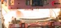
Overmolded part |
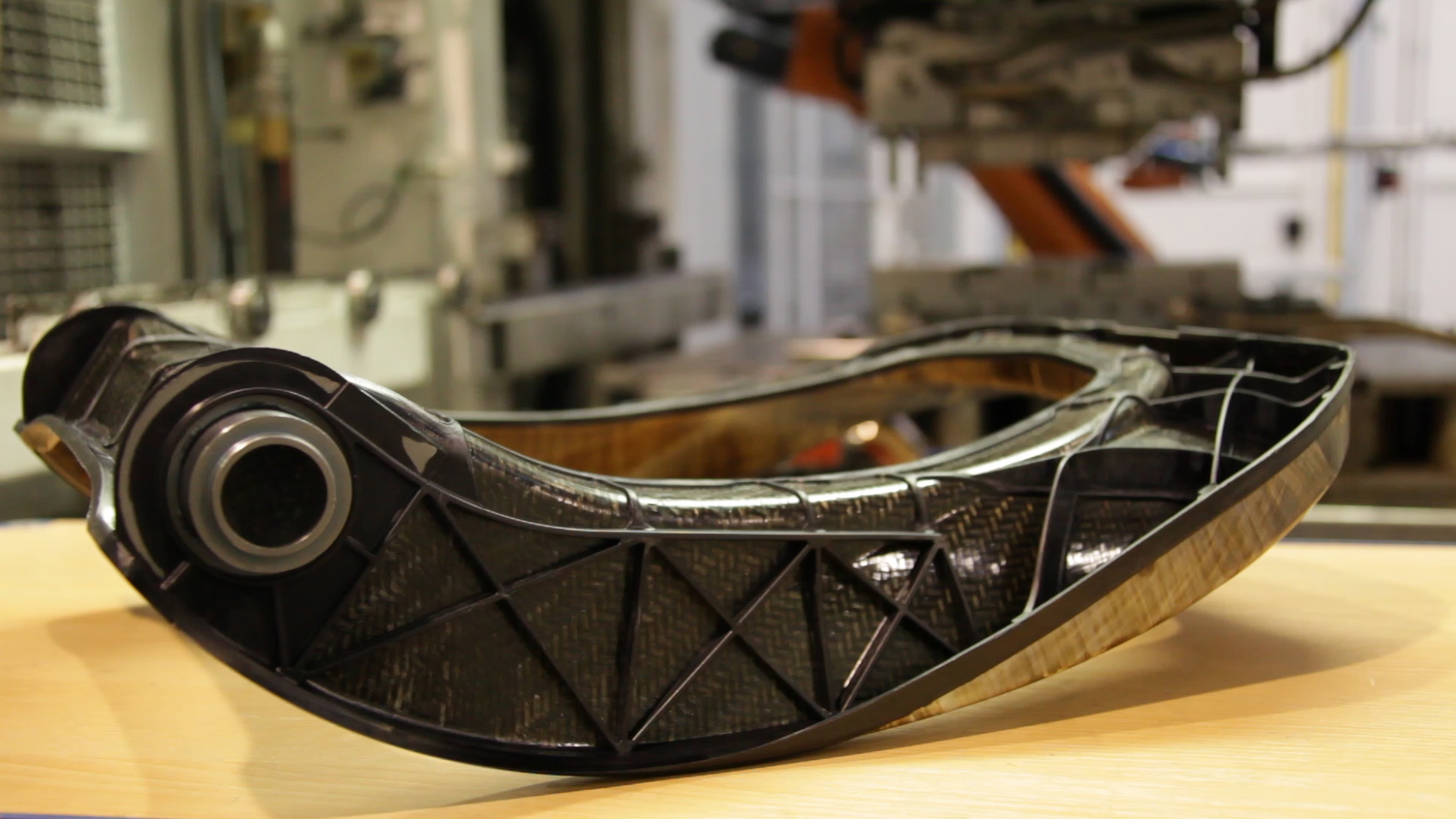
Automotive seat back (Demos Project with Faurecia) |
Multi-thickness, multi-material L-shaped demonstrator |
SOURCE: Cetim and Pinette Emidecau Industries.
Hundreds of Demonstration Parts
“We have demonstrated several hundred parts,” says Bordellier. “We can produce one preform every 40 seconds, and this preform includes 13 patches.” Here, he describes a multi-thickness, multi-material, L-shaped demonstrator which integrates 13 patches of 1.5-mm, 2-mm and 3-mm thick organosheet and UD tape. This part featured a preform built in 40 seconds, conduction-heated in 50 seconds, IR heated in 60 seconds and pressed using a two-cavity mold in 60 seconds for a total cycle time of fewer than 77 seconds per each 6-mm thick part with in-molded plastic and metal fittings and inserts.
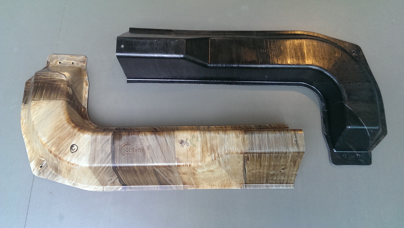
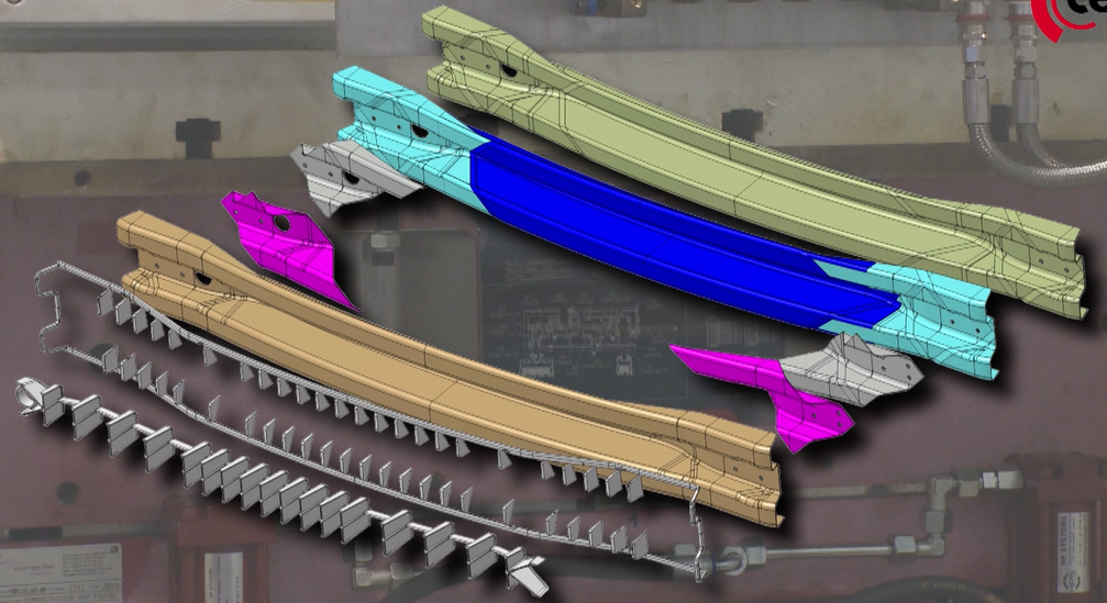
Another demonstration project is the QSP bumper beam, which reduces weight and material use by up to 25 percent and waste from 40-50 percent to 0-15 percent vs. a mono-thickness part. This also features a preform built in 40 seconds but the thicker part requires longer heating cycles. It is conduction heated in 90 seconds, IR heated in 95 seconds and pressed in 80 seconds to produce a 4.5-6-mm thick, net shape part with in-molded holes.
“This was a collaborative project with S.N.O.P. (Villepinte, France),” says Bordellier, noting that “cycle time will increase with part size and thickness. He also points out, “with the bumper beam we can build two preforms in 40 seconds, but with smaller preforms, we could build four or more in the same time period.”
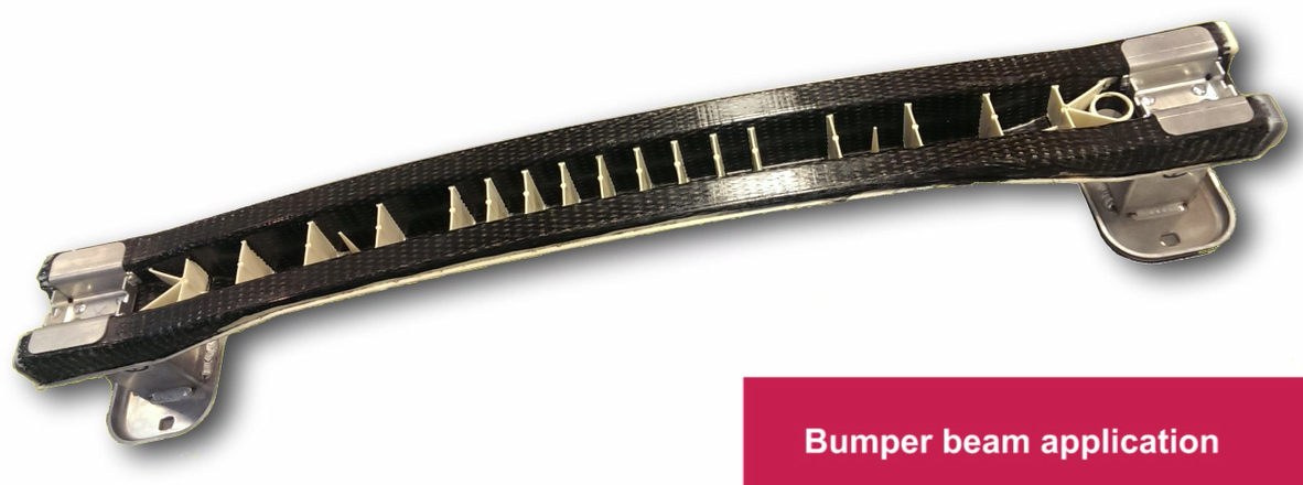
|
|
SOURCE: Cetim.
Another advantage demonstrated with the bumper beam was a 0-percent waste. “We designed the part to avoid small cutting so it is quite square in shape,” Bordellier explains. “During the design development, we made process simulations and integrated these for the final patch preform design for this part.”
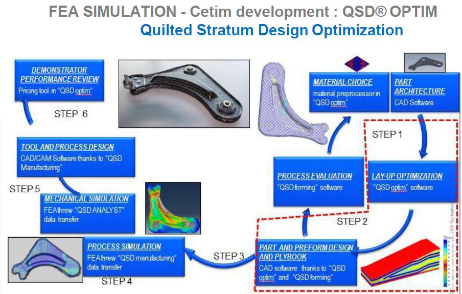
Quilted Stratum Design (QSD)
Another key aspect of QSP and also a service offered by Cetim and its partners is design. “There is currently no tool on the market to help design multi-thickness preforms,” says Bordellier, “that is, to help identify the best thickness and stiffness distribution. So we have developed QSD Optim.”
SOURCE: Cetim.
This software tool comprises two levels:
Level 1 is a macro optimization with nonhomogeneous material using OptiStruct finite element analysis (FEA) software from Altair (Troy, MI) and MATLAB software by MathWorks (Natick, MA).
Level 2 is a mesoscopic optimization with stacking sequence table using MATLAB and verification using Abaqus (Dassault Systèmes, Vélizy, France and Waltham, MA) and Altair OptiStruct, etc. to evaluate the best stacking sequence.
“We are working to automate these two steps together,” he adds, noting Cetim is exploring a partnership with Altair to put this design tool on the market.
“We are also working with process simulations, or what we call QSP Forming.” Bordellier explains that this optimization incorporates shape, thickness and ply orientation as it simulates forming of the flat preform into the final 3D part in the press. “One of our goals is to find ‘no scrap’ ply shapes,” he adds.
Other Areas of Composites Development
Composites design, analysis and simulation is, in fact, a major focus for Cetim. “We can integrate process defects enabling analysis of damage progression and damage tolerance,” says Bordellier. “We also develop process simulations to form a complete loop, for example, thermoforming analyses. You must get the right behavior during thermoforming in order to produce good parts.” He explains that in order to produce the best parts, it is first necessary to achieve the best simulation. “There is a chain between process simulation and production simulation.”
In this area, a key partner is the French office of national research into aerospace applications Onera (Palaiseau), École Centrale of Nantes (ECN)—GeM department and École Nationale Supérieur of Cachan (ENS Cachan). Cetim also has a partnership with Imperial College of London regarding the progression of damage in thermoplastic window frames for aircraft.
Cetim also excels in physical testing of composites, with its Etim SAS subsidiary offering dramatically faster mechanical property testing for production and certification. For example, a small test for certification requires only 3-5 days vs. 30 days required previously.
Cetim has also developed a thermoplastic 3D filament winding process called Spide TP in partnership with AFPT (Dörth, Germany). Bordellier says the process can produce Type V pressure vessels using carbon fiber and polyetheretherketone (PEEK) in both 2.5-m and 6-m diameters. It uses AFPT fiber placement heads and technology, a single 4-kW laser heating system and single compaction roller. Heating is controlled using a thermal camera so that it manages the laser power when the winding head slows or speeds up.
“This is filament winding, not automated fiber placement (AFP),” says Bordellier, who understands both technologies very well, with Airbus’ Flash TP system in development next door which indeed uses AFP technology from Coriolis (Queven, France). “We’ve been working on this system for 2-3 years,” he adds, noting, “consistency of tape is the key. If the thickness varies, you have quality issues.”


.jpg;maxWidth=300;quality=90;format=webp)
Related Content

Cycling forward with bike frame materials and processes
Fine-tuning of conventional materials and processes characterizes today’s CFRP bicycle frame manufacturing, whether in the large factories of Asia or at reshored facilities in North America and Europe. Thermoplastic resins and automated processes are on the horizon, though likely years away from high-volume production levels.
Read More
Materials & Processes: Composites fibers and resins
Compared to legacy materials like steel, aluminum, iron and titanium, composites are still coming of age, and only just now are being better understood by design and manufacturing engineers. However, composites’ physical properties — combined with unbeatable light weight — make them undeniably attractive.
Read More
Plant tour: Joby Aviation, Marina, Calif., U.S.
As the advanced air mobility market begins to take shape, market leader Joby Aviation works to industrialize composites manufacturing for its first-generation, composites-intensive, all-electric air taxi.
Read More
Materials & Processes: Resin matrices for composites
The matrix binds the fiber reinforcement, gives the composite component its shape and determines its surface quality. A composite matrix may be a polymer, ceramic, metal or carbon. Here’s a guide to selection.
Read MoreRead Next

Automated Preforming, Part 4: Drapability Testing
Textechno discusses how this test works, the new German test standard and its benefits for composites
Read More
Automated Preforming, Part 2: Glide Forming
Flat layups are shaped into stringers with different cross-sections, lengths, thicknesses and curvatures using a single machine at rates up to 10 mm per second.
Read More
From the CW Archives: The tale of the thermoplastic cryotank
In 2006, guest columnist Bob Hartunian related the story of his efforts two decades prior, while at McDonnell Douglas, to develop a thermoplastic composite crytank for hydrogen storage. He learned a lot of lessons.
Read More