
Tooling up for larger launch vehicles
NASA and Janicki Industries demonstrate composites’ cost advantage in tooling for fabrication of 10m/33 ft diameter payload fairing for next-generation launch vehicle.


This artist’s conception shows NASA’s future Space Launch System rising from a launch pad. Source: NASA/MSFC
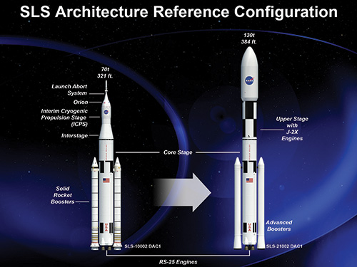
An artist’s rendering of potential Space Launch System configurations. The flexible designs share a basic core-stage and allow for different crew and cargo flights as needed, promoting efficiency, time and cost savings. The SLS payload fairing can be seen in this image, at the top of the launch vehicle on the right — the SLS at left shows the Orion crew module, which requires no fairing. Source: NASA
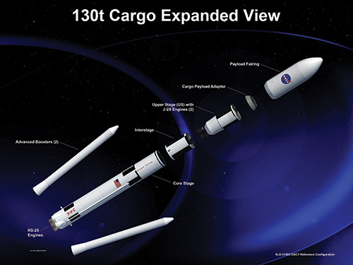
This exploded view of the SLS shows the large-diameter payload fairing at far right. Source: NASA
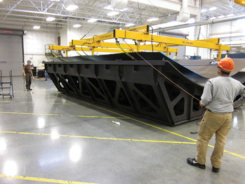
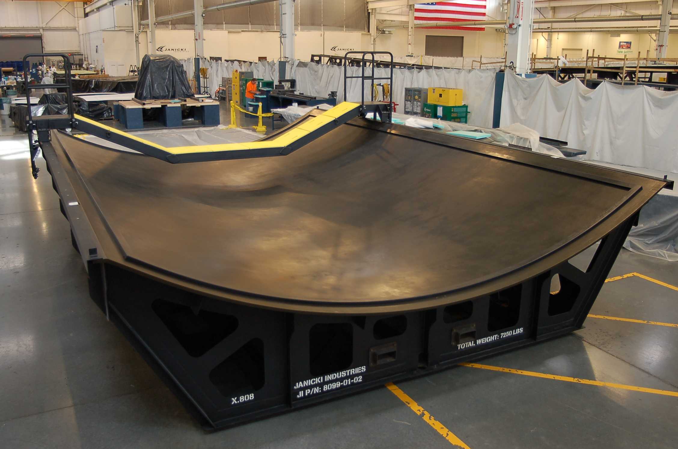
The final 1/6th-arc payload fairing segment tool alone and (in inset) complete with caul tooling and support fixtures. Source: Janicki Industries
Step 1: The finished, “high-temperature” pattern, in the mill bay after CNC machining. Source: Janicki Industries
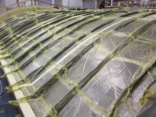
Step 2: VARTM infusion of the carbon fiber/epoxy “subsurface” facesheet. Source: Janicki Industries
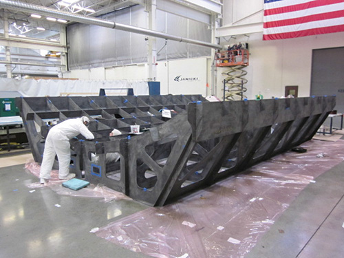
Step 3: Assembly of the VARTM carbon fiber/epoxy substructure components. Source: Janicki Industries
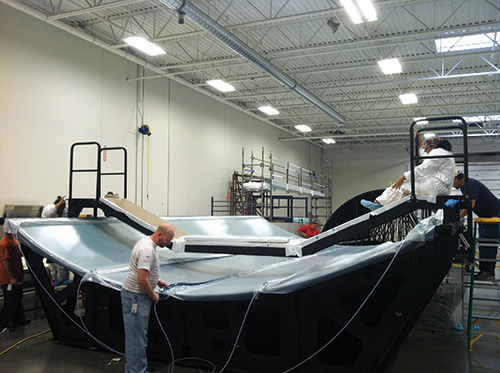
Step 4: Assembly of substructure to subsurface facesheet. Source: Janicki Industries
.jpg)
Step 5: Cure of tool substructure/subsurface assembly, in modular oven. Source: Janicki Industries
Step 6: Lay up of BMI topcoat and vacuum bag preparation for OOA cure. Source: Janicki Industries
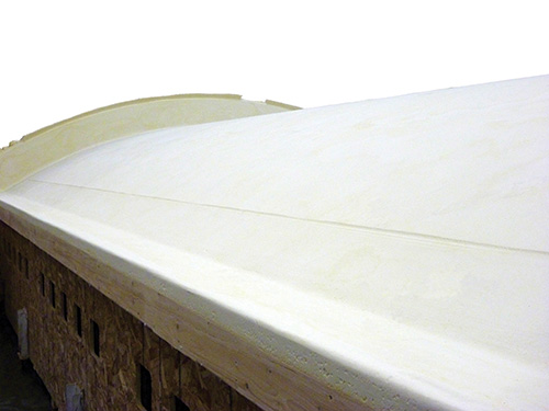
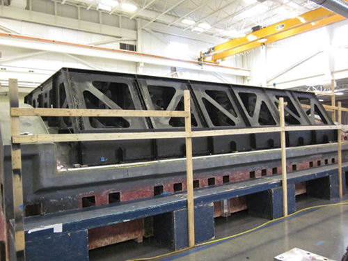
Step 7: Final configured tool, with edge bars. Source: Janicki Industries


The Space Launch System (SLS) will be the next heavy-lift launch vehicle for the National Aeronautics and Space Admin. (NASA, Washington D.C.). Composites have been chosen for both the launch vehicle structures and tooling because they offer performance and cost advantages over metals.
As part of a three-year program to develop and demonstrate composite tooling and fabrication technology, Janicki Industries (Sedro-Woolley, Wash.) began working with NASA in 2010 to design tooling for a 1/6th-arc SLS fairing segment. Each segment measures 8.5m by 5.5m (28 ft by 18 ft), and six of them will be assembled to form the barrel section of the payload fairing for the SLS launch vehicle. NASA’s objective was to demonstrate that cost-effective production of a lightweight composite structure is possible. “Our capabilities lined up well with NASA’s goals in this program,” explains Matt Robson, project manager at Janicki, “including out-of-autoclave processing, fabrication of large-scale tooling and pioneering of new processes to meet unique project demands.”


SLS payload fairing
A launch vehicle’s payload fairing protects the satellites, instruments and other cargo during ascent and gives the payload section its aerodynamic shape. Typically, payload fairings have a cylinder-cone configuration. Some fairings feature a clamshell assembly, so the fairing halves can be jettisoned after the rocket exits the earth’s atmosphere.
Boeing has made 4m and 5m (13.1-ft and 16.4-ft) diameter composite payload fairings for the Delta IV, and ATK (Clearfield, Utah) has made a 5m diameter Delta IV payload fairing using composites. RUAG Space (Zurich, Switzerland; renamed to Beyond Gravity) produces composite payload fairings for the European Ariane 5 and Vega and the American Atlas-V-500 launch vehicles. But unlike these previous vehicles, the SLS is designed to evolve. Its size and shape will change to meet a range of crew and cargo mission needs. In its initial Block 1 configuration, a 70-metric-tonne (more than 154,000-lb) SLS will launch the Orion Multi-Purpose Crew Vehicle (MPCV), as well as equipment, cargo and science experiments, for the uncrewed Mission 1 in 2017 and for Mission 2 — with as many as four astronauts — planned for 2021. The Block 2 configuration is designed to deliver almost twice the payload, at 130 metric tonnes (more than 286,000 lb), replacing the Orion MPCV with a 27.6-ft/8.4m diameter upper stage comprising a Payload Adapter and Payload Fairing.
A 10m fairing
“The Apollo program used capsules, not payloads with fairings or shrouds,” notes Dr. Jim Sutter, the materials lead for large-scale composite structures, who is evaluating OOA resins at the NASA Glenn Research Center (Cleveland, Ohio). NASA Glenn participates in agency-wide SLS composite development projects and manages payload fairing development, but six other NASA centers have made contributions. NASA Marshall Space Flight Center (Huntsville, Ala.) has taken the lead in composite manufacturing activities for most of these projects during the past five years. Sutter says the launch vehicle development history helps explain the many variations in SLS payload diameter.
The SLS began life during NASA’s Advanced Composite Technology (ACT) Project for Space Structures, headed by project manager Dr. Mark Shuart. Ares V was the heavy-lift launch vehicle at that time, with a payload capability of 117,000 lb (53 metric tonnes) to lunar orbit, or 270,000 lb (122.5 metric tonnes) to low-Earth orbit (LEO).
When the Constellation project was developed, all of the rocket components were 10m/32.8 ft in diameter, including the core stage and upper stage, so the payload fairing, which had to mate with these structures, was developed as a 10m diameter composite structure. Then NASA shut down the Constellation program. As NASA developed the Heavy Launch Vehicle (HLV), now called the Space Launch System (SLS), the diameter of the payload fairing was reduced, dictated by the payload requirements for planned missions.
“We don’t have an official launch on the books that uses a payload fairing until 2025,” says Sutter, “but that one will be an 8.4m [27.6-ft] diameter fairing because the vehicle configuration for that launch is for a 70-metric-tonne [154,324-lb] payload, not the 130-metric-tonne [286,601-lb] Block 2, which requires the 10m diameter fairing. This larger payload will only be used if missions are developed which require that volume and load capacity.” However, the lessons learned and technology developed on this 10m fairing — the most difficult to design and manufacture — will serve as a guideline for all future development efforts.
Selecting materials and processes
NASA’s specifications for the tooling said it would be used by Spirit AeroSystems (Wichita, Kan.) to build a honeycomb sandwich structure, using its gantry automated fiber placement (AFP) machine (supplied by Electroimpact, (Mukilteo, Wash.) and autoclave cure. The tool, then, had to fit within the machining envelope and Spirit’s autoclave. It also had to be capable of integration with the machining process. Specifically, the fiber placement head should be able to travel up the curved surface without encountering any interference or obstruction from the tool.
The tooling also would require support structures and fixtures to protect honeycomb-cored edges. Further, operators would need access to the interior of the part for core placement and vacuum bag preparation, and would require an inner mold line (IML) surface caul with a vacuum handling system (overhead equipment with suction cups to facilitate moving and positioning). The part — and, therefore, the tool — also would require a surface profile tolerance of ±0.508 mm (±0.020 inch). The structural design and analysis of the tooling was critical because of the myriad requirements combined with its scale: The tool’s overall dimensions would be 2.1m by 5.7m by 8.6m (6.8 ft by 18.8 ft by 28.3 ft) with a facesheet surface area of 52.1m2 (561 ft2).
“We did a full engineering analysis to make sure the tool met the deflection requirements and head load from the fiber placement machine,” Robson relates. This analysis was used to determine the minimum facesheet thickness and substructure requirements. An analysis also was required to design the complex tool surface layup.
To accommodate the size of the full 1/6th segment of the SLS payload shroud, multiple tool segments would be connected to make one large, monolithic skin segment. Robson describes, “Forward and aft flanges of the tool required roughly a 2-inch [50.8 mm] thickness to accommodate machine stock for a vacuum mating grid and index hardware features. In addition, the flange build up had to transition to facesheet hardware padups. Building a 2-inch padup into a 90º flange with integrated field padups presents flow and resin gel challenges using vacuum-assisted resin transfer molding [VARTM] because improper control of the resin can lead to porosity and/or vacuum integrity issues in the laminate.” Thus, scaled tests were conducted to prove the layup and infusion process prior to execution at full scale.
Because the final part will be made using aluminum honeycomb core, edge bars (or edge rails) were needed to prevent the high pressures exerted during autoclave cure from crushing the core along the final part’s edges. Typically, these are machined from metal, but Janicki decided not to use any metal due to the tooling’s large size and potential heat-mass issues during autoclave cure of the final part. Thus, the edge bars, and for the same reason, an IML caul plate, also were made from VARTM’d carbon fiber/epoxy.
The caul plate forms the IML on the bag side of the part to control the final part’s inner surface dimensions, which must be exact to enable accurate mating and assembly with the other payload fairing arc segments. Inexact tolerances at the IML also would make attaching details to the inside of the part difficult. The IML caul and edge bars were VARTM’d and cured on the final bismaleimide (BMI) topcoat surface of the tool.
“A lot of indexing was required for those edge bars,” Robson recalls, “because they were fabricated in multiple sections for pattern and producibility considerations, and each edge bar required a locating index set as well as deflection constraint index hardware.” There also was a scaffolding rail system that enabled workers to safely access the part from overhead, inner tool coordination holes and additional bars and structure needed to accommodate the AFP machine, all of which were designed and optimized for the coefficient of thermal expansion (CTE).
Janicki trialed different compatibility concepts, including variations in geometry, mechanical capacity and tool-mating options, eventually defining a mating concept that met with NASA approval.
It was determined that the substructure would be made using a high-temperature carbon fiber/epoxy laminate (materials proprietary to Janicki) because it met the strength and CTE requirements at a lower cost than using an autoclave carbon fiber/BMI system. BMI would be used in the tool because it matches the CTE of the part material and provides a more durable tool surface, but it would be used in the tool’s surface laminate only to minimize cost. It was also decided to cure both the tool’s substructure and surface OOA (at the time, Janicki did not have an autoclave that could accommodate the tool) using VARTM, because VARTM would easily meet the components’ requirements and achieve further cost savings.
Super-sized tooling substrate
“We started with what we call a ‘high-temperature’ pattern,” Robson recounts, “with reinforcement at strategic locations to stiffen the structure and resist movement at an initial cure temperature of 200°F [93°C].” He adds, “This pattern was very large, roughly 20 ft wide by 30 ft long [6m by 9m] — almost too large to fit through our doors.” The pattern was then CNC-machined to an accuracy of ±10 mil (±0.254 mm) and was used to lay up and infuse the tooling facesheet. The 600-ft2 (56m2) facesheet layup required 8,000 lb/3,629 kg of carbon fiber and 4,600 lb/2,087 kg of epoxy resin, but its final weight was much reduced after cure and machining.
At this point, the carbon fiber/epoxy substructure components, previously infused and assembled, were attached to the facesheet upside down. The whole assembly was transported into Janicki’s 100-ft by 24-ft by 14-ft (30m by 7m by 4m) modular oven and cured according to a proprietary schedule.
After cure, the tooling assembly was demolded and rolled over, with the facesheet up, so it could be machined using Janicki’s 100-ft by 20-ft by 8-ft (30.5m by 6.1m by 2.4m) CNC mill to correct for creep, expansion and contraction during cure. This ensured an accurate, constant-thickness surface on which Janicki could then lay up the final BMI topcoat.
BMI topcoat and OOA cure
Although Janicki had been developing OOA prepreg tooling for more than two years, the BMI prepreg layup required two to three weeks, partly due to the fact that this project was the first large-scale demonstration of the technology.
“Everything works great at a lab scale,” quips Robson. “So many more things can go wrong when you’re vacuum bagging the area of a small apartment.” Robson continues, “We did a 13-ft by 5-ft development test panel to establish the edge breathing requirements and that also helped us develop the debulking and cure cycles needed. We were also very careful to control the temperature and humidity of the environment during layup in order to control moisture.”
What’s more, Robson recalls that “the system for this project was originally intended for a 350°F [177°C] autoclave cure. So, one of our challenges was how to consolidate the BMI and get the properties required using only atmospheric pressure. Beyond that primary focus, we also refined our processing to reduce cost.”
The refinements included very tight control of the curing process. “We used thermocouple drawings, oven-map drawings and then ducting was very critical, all to manage temperature precisely. In other words,” Robson quips, “we had to manually manage the computer control of the cure because of the specifications of what the tool had to do in its final performance.”
The cure took 48 hours in a well-insulated oven. Robson adds, “The mass of this tool and the volume of space you have to heat takes a long time, so the ramps are slow.”
After curing, the tool went through final machining to scribe support tool index features and hardware, which would allow technicians to attach a variety of auxiliary tooling.
A standard timeline for a complex composite tool of this scale at Janicki is two to three months. Robson noted that using BMI added a few more weeks.
Not finished yet
Janicki’s contract included running a part on the tool to demonstrate tool performance. “We had already measured the tool’s temperature performance by installing thermocouples, and observed a ±5°F tolerance across the entire surface,” Robson recounts. The team was confident the tool would perform well.
It did. The team met, and actually exceeded, the tooling surface tolerance requirements. Laser metrology confirmed it was within +0.3022/-0.1118 mm (+0.0119/-0.0044 inch).
A final challenge was shipping the tool to Spirit AeroSystems for automated tape layup of cored payload fairing structures. “The tool qualified as a super load,” he says, “so just moving it down the road to our Hamilton facility was time-consuming.”
“The ultimate program goal is to build the full-scale cylinder and test it at NASA Marshall Space Flight Center,” says Robson. “We would love to make all of the production tooling for this program.” In the interim, Janicki has pursued a wide range of uniquely challenging composites projects and, in 2012 at its Hamilton, Wash., facility, also installed a 12-ft/3.6m diameter, 50-ft/15.2m deep autoclave capable of a maximum temperature of 550°F/288°C and pressures up to 150 psi or 10.5 kg/cm.
HPC recently took its readers along on a plant tour in “Janicki Industries: Breaking the mold." To read this article, click on its tile under "Editor's Picks" at top right.


.jpg;maxWidth=300;quality=90;format=webp)


Related Content

PRF Composite Materials introduces RP570 FR eXpress cure prepreg system
Ultra-fast, fire-retardant formulation targets snap cure press molding of structural components.
Read More
Busch expands autoclave solutions
Busch announces its ability to address all autoclave, oven and associated composites manufacturing requirements following the acquisition of Vacuum Furnace Engineering.
Read More
The state of recycled carbon fiber
As the need for carbon fiber rises, can recycling fill the gap?
Read More
Plataine unveils AI-based autoclave scheduling optimization tool
The Autoclave Scheduler is designed to increase autoclave throughput, save operational costs and energy, and contribute to sustainable composite manufacturing.
Read MoreRead Next

Janicki Industries: Breaking the mold
Once known only as a toolmaker, Janicki offers unique precision, production capability and problem solving as it pioneers leading-edge composites technology.
Read More
Composites end markets: Energy (2024)
Composites are used widely in oil/gas, wind and other renewable energy applications. Despite market challenges, growth potential and innovation for composites continue.
Read More
CW’s 2024 Top Shops survey offers new approach to benchmarking
Respondents that complete the survey by April 30, 2024, have the chance to be recognized as an honoree.
Read More