
Through-the-thickenss tensile strength testing using a curved beam
The in-plane strength properties of a composite material, axial and transverse tension and compression and in-plane shear, are usually the first to be considered in design. However, through-the-thickness (interlaminar) strength properties cannot be ignored. Through-the-thickness tensile strength, in particular, can be critical to structural performance.


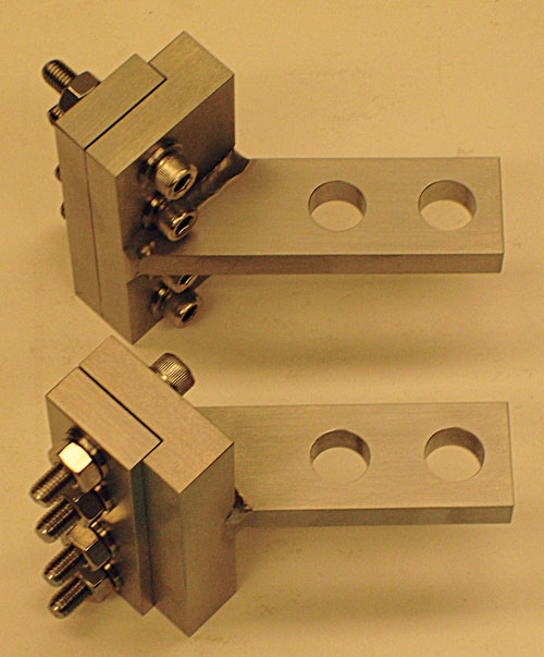
Fig. 1: Angle bend test fixture. Source: Dr. Don Adams

Dr. Donald F. Adams is the president of Wyoming Test Fixtures Inc. (Salt Lake City, Utah). He holds a BS and an MS in mechanical engineering from, respectively, the University of Illinois and the University of Southern California, and a Ph.D in theoretical and applied mechanics from the University of Illinois. Following a total of 12 years with Northrop Aircraft Corp., the Aeronutronic Div. of Ford Motor Co. and the RAND Corp., he joined the University of Wyoming, directing its Composite Materials Research Group for 27 years before retiring from that post in 1999. Dr. Adams continues to write, teach and serve with numerous industry groups, including the test methods committees of ASTM and the Composite Materials Handbook 17 (CMH-17).
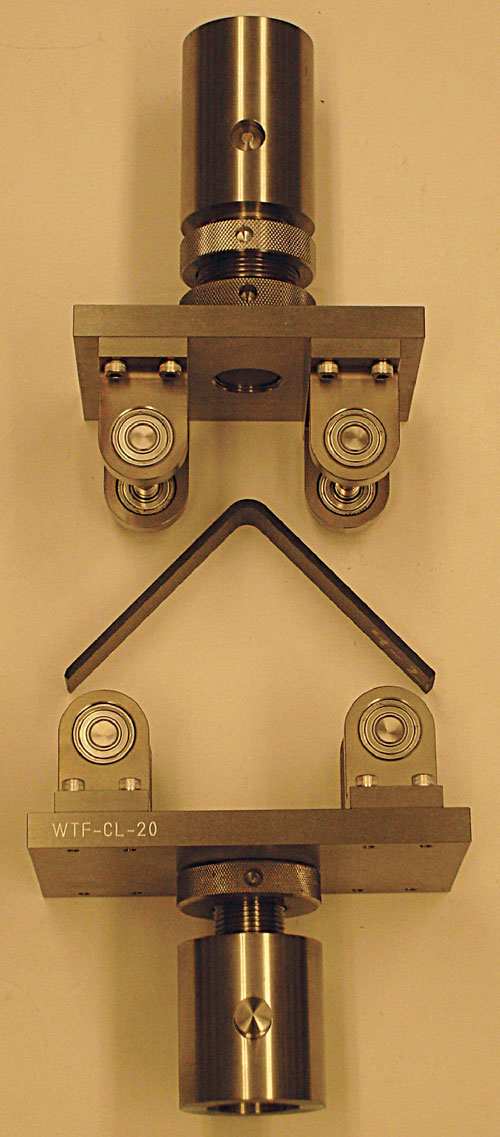
Fig. 2: ASTM D 6415 test fixture and test specimen. Source: Dr. Don Adams
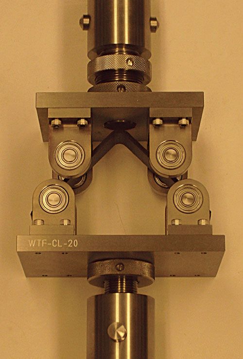
Fig. 3: ASTM D 6415 test fixture, with specimen loaded. Source: Dr. Don Adams
The in-plane strength properties of a composite material, axial and transverse tension and compression and in-plane shear, are usually the first to be considered in design. However, through-the-thickness (interlaminar) strength properties cannot be ignored. Through-the-thickness tensile strength, in particular, can be critical to structural performance. But the typical composite laminate is relatively thin, making it difficult to grip the material to perform a tensile test in this direction. There are several ways to circumvent this difficulty.
A unidirectional composite can be loaded in the in-plane transverse direction (commonly referred to as a 90° tensile test), with the assumption that this strength is at least approximately equal to the through-the-thickness strength. Defined in ASTM D 30391, this method presents at least two problems. First, it is difficult to perform a valid 90° tensile test. The material is very fragile and can be damaged during specimen preparation or as it is mounted in the testing machine. Any misalignments that occur during loading can induce bending, leading to premature failure and, as a result, low strength values. Further, the presence of induced bending is very difficult to detect. Also, the strength is sensitive to material defects, such as internal voids, and machining defects, such as nicks and induced edge cracks. The second problem is that it is risky, for design purposes, to make the potentially invalid assumption that the specimen’s through-the-thickness tensile strength is approximately equal to the in-plane strength.


A more logical approach is to perform a direct through-the-thickness tensile test on a laminate that is sufficiently thick to permit gripping. ASTM Standard D 7291, issued in 20072, governs this test method. However, because of fundamental differences in fabrication procedures, there is no assurance that the thick laminate will have the same properties as the much thinner laminate that will be used in a design. Alternatively, multiple layers of thin laminate can be adhesively bonded together to obtain a sufficiently thick panel. This is not an unreasonable approach, but it is difficult to determine what influence the multiple bond lines have on the measured strength. Unfortunately, the most intuitive solution, bonding a single thin laminate in between metal blocks and pulling it apart, isn’t an option: The mismatch in lateral (Poisson-induced) strains between the specimen and the bonding blocks can severely distort the test results.
A third approach uses a curved beam subjected to axial tensile loading. A number of test-fixture geometries have been proposed, all of which induce a combined axial tensile force and a bending moment. The specimen itself is either semicircular in shape or formed as a 90° angle with a controlled inner radius at the junction of the angle’s two legs. For either geometry, the ends of the specimen are pulled in an opening mode to induce failure in the curved section.
The most popular fixture for this test (Fig. 1) uses the same 90° angle specimen as shown in Fig. 2. The specimen legs are clamped in the holders, and tensile forces are applied, which opens up the 90° angle. The bending moment in the specimen is maximum at the bend. This moment induces a through-the-thickness tensile stress at the bend, which increases from zero at the inner and outer surfaces to a maximum near the midthickness. However, this is not the only stress present in this region of the specimen. Due to the bending moment, a maximum in-plane tensile stress occurs at the inside radius, decreasing to a maximum in-plane compressive stress at the outside radius. There also is a direct axial tensile stress due to the tensile loading. The ratio of bending to direct axial loading can be varied by changing the length of the lever arms. In any case, the stress state in the specimen region of interest is far from uniform. The concept is that because the through-the-thickness tensile strength is typically low relative to the in-plane strengths, the specimen will fail in the through-the-thickness mode first. There is presently no public standard governing this type of curved beam loading, although a number of organizations have their own in-house specifications. (The article by Jackson and Martin3 noted under “References,” below, is an excellent source of additional general information.)
Finally, there is one additional type of through-the-thickness tensile stress test method, and it is an ASTM standard, ASTM D 64154, first published in 1999. The test configuration is shown in Figs. 2 and 3. The 90° angle specimen, having a 6.4-mm/0.25-inch inside radius, is subjected to four-point bending, so that the bending moment is constant between the loading points. This differs from the tensile loading of a curved beam in that no direct axial tensile stress is induced. Thus, it produces a slightly less complex stress state than the fixture of Fig. 1, although in-plane bending stresses are still present. A valid through-the-thickness tensile failure is shown in Fig. 4.
These curved beam tests have another general deficiency in that it is difficult to fabricate a specimen that has a reasonably uniform fiber volume and minimal voids through the thickness in the region of the bend. Thus, in common with all of the other through-the-thickness tensile tests discussed here, the data scatter tends to be high, with coefficients of variation of 15 percent or more being common.
In summary, although curved beam strength testing is increasing in popularity and may be among the best methods currently available, it is still not ideal for determining a laminate’s through-the-thickness tensile strength. The search for a better method continues.
References
1 ASTM Standard D 3039-08, “Test Method for Tensile Properties of Polymer Matrix Composite Materials,” American Society for Testing and Materials, W. Conshohocken, Pa. (first issued in 1971).
2ASTM Standard D 7291-07, “Test Method for Through-Thickness Flatwise Tensile Strength and Elastic Modulus of a Fiber-Reinforced Polymer Matrix Composite Material,” American Society for Testing and Materials, W. Conshohocken, Pa. (first issued in 2007).
3Jackson, W.C, and Martin, R.H., “An Interlaminar Tensile Strength Specimen,” Composite Materials: Testing and Design (11th Volume), ASTM STP 1206, E.T. Camponeschi, Jr., ed., American Society for Testing and Materials, W. Conshohocken, Pa., 1993, pp. 333-354.
4ASTM Standard D 6415-06, “Test Method for Measuring the Curved Beam Strength of a Fiber-Reinforced Polymer-Matrix Composite,” American Society for Testing and Materials, W. Conshohocken, Pa. (first issued in 1999).


.jpg;maxWidth=300;quality=90;format=webp)


Related Content

Measuring ply-wise deformation during consolidation using embedded sensors
Strip-type shape sensor method claims real-time measurement of ply-wise deformation.
Read More
Composite test methods (and specifications) for fiber-reinforced concrete structures
While initially focused on transitioning existing standards published by the American Concrete Institute, the relatively new ASTM Subcommittee D30.10 is developing new standardized test methods and material specifications for FRP composites.
Read More
Notched testing of sandwich composites: The sandwich open-hole flexure test
A second new test method has been standardized by ASTM for determining notch sensitivity of sandwich composites.
Read More
Notched testing of sandwich composites: The sandwich open-hole compression test
A new ASTM-standardized open-hole compression test method seeks to determine the notch sensitivity of sandwich composites.
Read MoreRead Next

From the CW Archives: The tale of the thermoplastic cryotank
In 2006, guest columnist Bob Hartunian related the story of his efforts two decades prior, while at McDonnell Douglas, to develop a thermoplastic composite crytank for hydrogen storage. He learned a lot of lessons.
Read More
Composites end markets: Energy (2024)
Composites are used widely in oil/gas, wind and other renewable energy applications. Despite market challenges, growth potential and innovation for composites continue.
Read More
CW’s 2024 Top Shops survey offers new approach to benchmarking
Respondents that complete the survey by April 30, 2024, have the chance to be recognized as an honoree.
Read More