
The rise of rapid manufacturing
An outgrowth of rapid prototyping, tool-free additive fabrication technologies have the potential to form small, limited-run composite parts directly from CAD data.
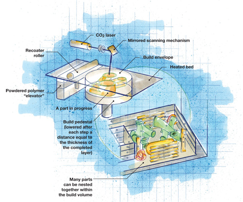
Although this diagram illustrates the laser sintering method, other methods have similar basic configurations. In both Stereolithogrpahy and Digital Light Processing, the polymer is in liquid form. Fused Deposition Modeling and 3D Printing substitute, respectively, an extrusion head and jetting print head in place of the laser system). Illustration: Karl Reque
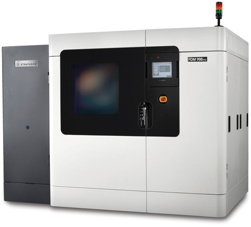
The Fortus FDM 900mc, a fused deposition modeling system from Stratasys Inc. (Eden Prairie, Minn.), performs CAD-to-part fabrication using extruded thermoplastics. Source: Stratasys Inc.
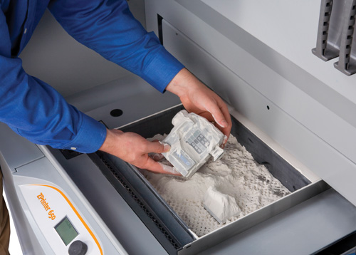
A 3-D printed video camera model is removed from a ZPrinter. Source: Z Corporation
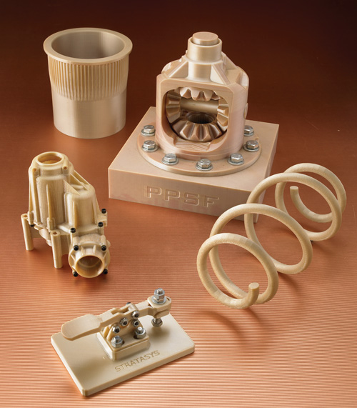
These complex parts were formed, several in one piece, from extruded PPS (polyphenylene sulfide) thermoplastic material, using the Fortus FDM 900mc system pictured above. Source: Stratasys Inc.
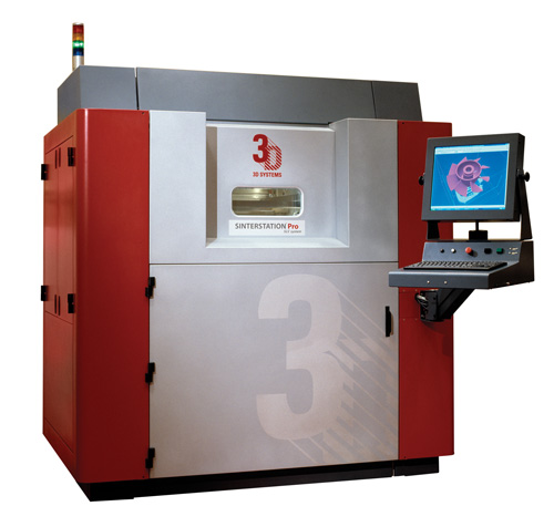
The Sinterstation Pro SLS, a laser sintering system supplied by 3D Systems (Rock Hill, S.C.), builds net-shape 3-D parts direct from CAD data, using laser-fusable powdered materials. Source: 3D Systems
Stereolithography was the build method and 3D System’s Accura Bluestone the material used to build this wind tunnel test model for a Formula 1 racing team’s brake cooling duct. Source: Renault F1
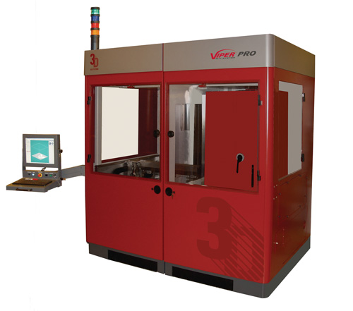
The Viper Pro, a stereolithography system supplied by 3D Systems (Rock Hill, S.C.) produces net-shape 3-D parts direct from CAD data, using laser-fusable liquid materials. Source: 3D Systems
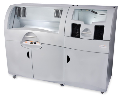
The ZPrinter 650 from Z Corporation (Burlington, Mass.) can produce single or multiple parts (stacked or nested, without support structures) in as many as five colors in a few hours. Source: Z Corporation
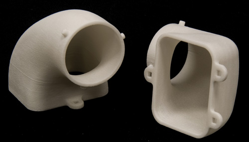
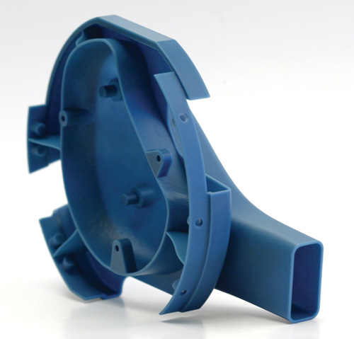
These two one-piece aerospace ducts were built using the Selective Laser Sintering process and DuraForm HST material supplied by 3D Systems (Valencia, Calif.). Note the detail captured in the parts. Source: 3D System


Cutting time and cost out of molding cycles is a priority for composites manufacturers in every market they serve. As molders approach the practical limits to process speed and cost efficiency, the focus of their efforts has increasingly sharpened on one of the slower and most costly pieces of the manufacturing puzzle — toolmaking.
Strategies for reducing the cost and shortening the fabrication cycle for tooling abound. New materials and innovative technologies are regularly introduced toward that end and covered in the pages of this magazine. One recent initiative, however, has as its goal to significantly reduce the impact of tooling on product cost by eliminating it. A step change in the development of rapid prototyping (RP) concepts that were introduced more than 20 years ago, rapid manufacturing (RM) describes a collection of similar, but separately developed additive fabrication technologies — that is, automated processes that assemble a three-dimensional (3-D) object from a series of nominally two-dimensional (2-D), cross-sectional layers of specialized materials.


The basics of additive building
All additive fabrication techniques begin with a CAD drawing. Solid-model CAD data is converted, using special software, into a file format that represents a 3-D surface as an assembly of planar triangles. Additional, and typically proprietary, software then is used to “slice” this virtual image into very thin 2-D cross-sectional patterns. This layer data is used to instruct additive fabrication machinery as it builds a 3-D physical model by “stacking” the 2-D slices.
Today, five additive fabrication methods are in use in this industry:
Stereolithography (SLA), patented in 1986, was the first fully commercial rapid prototyping technology and is still the most widely used. In the SLA process, the part model is built on a platform positioned just below the surface in a vat of liquid, photocurable polymer, usually an epoxy or acrylate resin. A low-powered ultraviolet (UV) laser, programmed with the previously created CAD slice data, traces out the first layer of the part with its highly focused UV light beam, scanning and curing the resin within the boundaries of the slice outline until the entire area within the slice cross section is solidified. An elevator then incrementally lowers the platform into the liquid polymer to a depth equal to the slice thickness, and a sweeper recoats the solidified layer with liquid polymer. The laser then traces out a second layer on top of the first. The process is repeated until the part is complete. Depending on the geometry of the part, mechanical supports may need to be built into the part during the build to contain the liquid. After removal from the vat, supports are removed from the part, which then is placed in an UV oven for additional curing.
Typical tolerances for an SLA part with an edge ranging in length to 200 mm/8 inches is ±0.1 mm/±0.004 inch and about ±0.4 mm/±0.016 inch for a part with an edge up to 500 mm/19.7 inches long.
Since 1988, 3D Systems Corporation (Rock Hill, S.C.) has been the sole manufacturer of SLA RP machines. The company currently offers a line of five machines, the newest of which, the Viper Pro, is capable of building a single part as large as 1,500 mm by 750 mm by 500 mm (59 inches by 29.5 inches by 19.7 inches) or producing multiple smaller parts with the same or different build configurations. The company says the system is capable of achieving a surface finish “normally associated with CNC machining.”
Fused Deposition Modeling (FDM), commercialized in 1990 by Stratasys Inc. (Eden Prairie, Minn.), is the second most widely used RP process. FDM builds parts of ABS (acrylonitrile butadiene styrene), polycarbonate and other resins noted for toughness. Often, it is chosen when part durability is paramount.
FDM builds a 3-D object one layer at a time. A plastic filament is unwound from a coil, supplying material to a heated extrusion nozzle, which controls the flow. The nozzle is mounted over a mechanical stage, and can be moved horizontally and/or vertically. The nozzle moves over the stage, which is coated with a support material, depositing a thin bead of extruded plastic. For ABS, the thickness of that layer is typically 0.25 mm/0.010 inch, which roughly defines the tolerance one can expect to hold on an FDM part. Successive extruded layers bond with the previous layers, then harden immediately. The entire system is contained in a chamber held at a temperature just below the melting point of the plastic. No postprocessing is required after the part is removed from the chamber.
Although Stratasys is the sole manufacturer of FDM machines in North America under the trade names Dimension and Fortus, several Asian companies are licensed to build them for sale in Asia. The company’s Fortus FDM 900mc comes with a 914-mm by 610-mm by 913-mm (36-inch by 24-inch by 36-inch) build envelope. The machine comes with Insight, a software tool that imports part files, automatically creates part slices and generates support structure data as well as material extrusion paths.
Laser Sintering (LS) was developed in the late 1980s by Austin, Texas-based DTM Corp. The technology was purchased by 3D Systems in 2001. In a method similar to that employed in stereolithography, 3D’s Selective Laser Sintering (SLS) process uses the heat of a CO2 laser to process a variety of materials in powdered rather than liquid form, including nylon, and glass fiber- or carbon fiber-filled nylons. In an enclosed unit about the size of a print shop photocopy machine, a CO2 laser and a mirrored reflector system are mounted over a build table or pedestal, which supports the part. A roller distributes a thin layer of powdered material over the pedestal surface, and then the mirror system directs the laser beam onto the powder layer. As the beam scans back and forth across the material, the laser turns on and off, selectively sintering the powder (heating the powder grains to melt or fusion temperature) in a pattern identical in size and shape to the cross-sectional slice derived from the converted CAD file. The pedestal is then lowered the distance of the layer thickness, another layer of powder is rolled over the cooled and now solidified first layer, and the sintering process is repeated, bonding the second layer to the first. The process repeats, in layers of 0.08 mm to 0.15 mm (0.003 inch to 0.006 inch) thickness, until the part is complete. Tolerances range from ±0.1 mm/±0.04 inch for a part with a 100-mm/3.9-inch edge to ±0.75 mm/±0.03 inch for a part with a 500-mm/19.7-inch edge.
The primary benefit of SLS is the produced part’s durability and the fact that SLS users may choose from the widest range of engineering-grade materials available in the RP industry. Unlike stereolithography, SLS does not require support structures during the forming process because the unused powdered material that surrounds the part provides support. Moreover, SLS requires no postcure. Disadvantages include relatively low accuracy/repeatability, poor surface finish and comparatively high porosity.
3D Systems’ line of SLS machines includes the Sinterstation Pro SLS 140 and 230 models and the Sinterstation HiQ. The SLS 230 offers the largest build volume, 550 by 550 by 750 mm (22 by 22 by 30 inches), but the HiQ is equipped with a Beam Delivery Optics system and a more powerful laser that reportedly nearly doubles vertical build speed.
In Europe, laser sintering units are manufactured by EOS GmbH (Electro Optical Systems), a Munich, Germany-based machinery manufacturer. Its EOSINT 800 machine is reportedly the first to process high-performance polymers at temperatures as high as 385°C/725°F within a build window of 1,600 by 800 by 1,370 mm (63 by 32 by 54 inches). EOS also offers Integrated Process Chain Management (IPCM) for optimization of the process flow, and software that prepares 3-D CAD data, including EOSPACE, which automatically nests parts to save space in the build envelope.
Digital Light Processing (DLP), developed by Austin, Texas-based Texas Instruments Inc., supports a line of Computer Aided Modeling Devices (CAMOD) developed by EnvisionTEC Inc. (Ferndale, Mich.). This technology, like the stereolithography platforms, uses light-curable resins, but reportedly processes them faster (about 25-mm/1-inch per hour) using a continuous process (rather than incremental layering) that involves Mask Projection, that is, projecting the entire image onto a liquid photopolymer bath rather than scanning over successively applied layers of powdered or liquid resin with a point energy source or depositing layers of material and applying heat. Further, the continuous-build technique eliminates the visible and tactile stair-stepped part surface that is characteristic of layer-based additive fabrication. EnvisionTEC’s Perfactory Xede machines use single or multiple DLP-based projectors to produce multiple parts within a comparatively small 457- by 304- by 508-mm (18- by 12- by 20-inch) build envelope. Finished parts reportedly have the same properties as engineering plastics, such as ABS, high-density polyethylene or polypropylene.
3-D Printing is the most recent entry into this market, making its debut in late 2007 when Objet Geometries (Rehovot, Israel) launched its Connex500 3D system, which builds 3-D parts by jetting successive layers of material. Designed to print one or two build materials simultaneously, the system is based on Objet’s PolyJet Matrix printing technology, an advanced version of what most are familiar with as inkjet technology. Objet Studio for Connex software manages the process, using converted CAD data to create print files.
In operation, the system funnels either one or two materials to a dedicated liquid system connected to the PolyJet Matrix block, which contains eight printing heads, each containing 96 nozzles. Two perfectly synchronized printing heads are designated for each material, including an easily removed, water-soluble, gel-like support material.
Objet coined the term Digital Material to describe the resulting “composite” layer when two materials are jetted simultaneously, permitting a wide range of specific values for tensile strength, elongation-to-break, HDT and Shore A values. The company contends the system can build parts at a rate of 12-mm to 20-mm (0.47-inch to 0.79-inch) thickness per hour with part walls as thin as 0.6 mm/0.024 inch. Layer thicknesses as small as 16µ permit smoother part surfaces. Part accuracy ranges from ±0.1 mm to ±0.3 mm (±0.004 inch to ±0.01 inch). However, net build size is currently limited to 490 by 390 by 200 mm (19.4 by 15.4 by 7.9 inches), and it is too early to gauge the impact 3-D printing is having on this market.
In the U.S., Z Corporation (Burlington, Mass.) offers a five-head system, the ZPrinter 650, with a maximum build size of 254 by 381 by 203 mm (10 by 15 by 8 inches). At a build speed of two to four layers per minute, with user selectable 0.089- to 0.102-mm (0.0035- to 0.004-inch) layer thickness, the system can produce single or multiple parts (stacked or nested, without support structures) in single or multiple colors (as many as five, one from each print head) in a few hours. Printing materials are identified as water-cured “composites,” but the company’s systems, thus far, have been targeted primarily to prototyping/modeling.
(For help in visualizing additive fabrication processes, see the artist's rendition at right. Although it illustrates the LS method, other methods have similar basic configurations. IN SLA and DLP, the polymer is in liquid form. Fused Deposition Modeling and 3D Printing substitute, respectively, an extrusion head and jetting print head in place of the laser system).
Is there RM in your future?
As the term “rapid prototyping” implies, these processes were originally intended and still enable part designers and engineers to bypass the need for prototype tooling, enabling them to make a prototype in a few hours to evaluate form and fit characteristics and, in some cases, to serve as test articles, such as those for wind tunnel evaluation of part aerodynamics. However, designers have realized that there is the potential to use additive fabrication systems to make production parts as well.
Notable RP industry consultant and analyst Terry Wohlers of Wohlers Associates Inc. (Ft. Collins, Colo.) observes that users of additive fabrication technology derived about 12 percent of their revenues from some type of manufacturing in 2008 compared with just 3.7 percent in 2003. That’s about $132 million for manufactured parts.
Although the portion of that figure that can be attributed to composite manufacturers is unknown, but likely small at this point, the trend toward rapid manufacturing appears to have special relevance for the composites industry. Equipment manufacturers, RP service bureaus and, in some cases, end-users have developed composite materials compatible with additive fabrication processes (see the sidebar entitled “Rapid manufacturing: The materials,” below), but the low production volumes that characterize some segments of the composites industry make tool-free manufacturing or, in some cases, rapid manufacturing of short-run tools, a viable option for small, often specialized niche parts.
Indeed, rapid manufacturing, as young as it is, already has acquired several inventive descriptors, including solid free-form manufacturing, e-Manufacturing and direct digital manufacturing. While it is far too early to declare this phenomenon revolutionary, additive fabrication is making inroads into composites manufacturing (see two examples in this issue, on pp. 27 & 46). Each of the technologies previously discussed are proving capable — when conditions are favorable — of offering an affordable alternative to costly, time-consuming commercialization cycles. To be sure, favorable conditions are likely to include relatively small part size. Additive fabrication machine build envelopes currently impose physical limits while the speeds at which they operate almost certainly will exclude production of large structures in the foreseeable future. That said, Wohlers believes that additive fabrication of end-use parts is “the next frontier.”


.jpg;maxWidth=300;quality=90;format=webp)


Related Content

Large-format 3D printing enables toolless, rapid production for AUVs
Dive Technologies started by 3D printing prototypes of its composite autonomous underwater vehicles, but AM became the solution for customizable, toolless production.
Read More
Plant tour: Albany Engineered Composites, Rochester, N.H., U.S.
Efficient, high-quality, well-controlled composites manufacturing at volume is the mantra for this 3D weaving specialist.
Read More
Materials & Processes: Fabrication methods
There are numerous methods for fabricating composite components. Selection of a method for a particular part, therefore, will depend on the materials, the part design and end-use or application. Here's a guide to selection.
Read More
Sulapac introduces Sulapac Flow 1.7 to replace PLA, ABS and PP in FDM, FGF
Available as filament and granules for extrusion, new wood composite matches properties yet is compostable, eliminates microplastics and reduces carbon footprint.
Read MoreRead Next

Focus on Design: The promise of rapid manufacturing
Selective Laser Sintering technology and new materials abbreviate the design phase and produce a key part for a new motorcycle racing engine.
Read More
Rapid Manufacturing, Part II: Pioneer Applications
Harbingers of what could be a significant trend, these composites manufacturers demonstrate the potential of additive fabrication and several innovative materials in tool-free manufacture of complex components.
Read More
From the CW Archives: The tale of the thermoplastic cryotank
In 2006, guest columnist Bob Hartunian related the story of his efforts two decades prior, while at McDonnell Douglas, to develop a thermoplastic composite crytank for hydrogen storage. He learned a lot of lessons.
Read More