
The craft of aircraft repair
As the use of composites on commercial and military aircraft grows, repair facilities seek more science in what remains a primarily manual art.


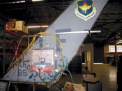
Source: Zimac LaboratoriesThe U.S. Air Force successfully demonstrated the Zimac HBS bonding system's precise control of cure profile on this F-16 tail fin repair. Five heat-source cells attached to a caul plate over the 35.5-cm/14-inch square patch are used to "shape" the heating as needed. Cells positioned around the patch act as heat dams over stringers. Thermocouples for each cell provide temperature feedback.
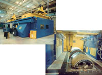
Source: American GFMAn RMH-50 6-axis ultrasonic cutter and router from American GFM, like this one that cuts graphite honeycomb core parts for the Boeing 737-NG, is a model of the Inspection and Repair Preparation Cell into which automated repair systems will be mounted and integrated.
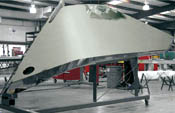
Source: Texas Air CompositesThe Boeing 737-NG winglet, a dozen of which Texas Air Composites (TAC) has repaired, suffers various impact and lightning-strike damage. TAC has invested in high-end fixtures for this component, anticipating a regular repair demand.
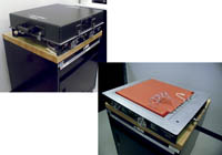
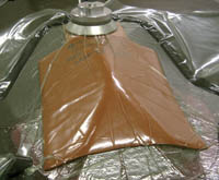
Source: U.S.A.F. 361 Training Squadron Detachment 2For prepreg repair patches, the Atec Inc. Double-Vacuum Debulking (DVD) unit reportedly produces 15 percent greater compaction than vacuum bagging alone.
Source: HEATCON Composite SystemsHEATCON's stretchable heat blanket improves heating uniformity over repair patches on complex contours.
Unlike manufacturers of composite aerospace components, who have, especially of late, sought labor-reducing means to automate production, via resin transfer molding and the like, those who repair what they build still practice a primarily manual occupation. At repair depots around the world, the tradition has been to focus less on repair technologies than on proper repair techniques and knowledgeable technicians. The advent of more composites-intensive commercial and military aircraft — most notably, the forthcoming Airbus A380 and Boeing 787 passenger jets — will fuel the need for high-quality repairs, especially on fuselages, wings and other safety-critical primary structures. While there are technological innovations now in development that promise to strengthen the science of composite repair and simplify the repair technician's task, most have yet to attain proof of concept, much less commercialization. In the meantime, those who perform composite repairs and the composites training companies that serve them are looking for ways to keep repair artisans as well prepared as possible.
"The aircraft industry is recognizing a need for better training," says Michael Hoke, president of Abaris Training Resources Inc. (Reno, Nev.). He notes as evidence the fact that enrollment in his firm's composite repair courses has increased 50 percent since 2001 and might have been much higher had it not been for the negative economic impact the terrorist attacks of September 11 that year have had on commercial airlines. Much of the growth since 2001 has come from the military, although the commercial airline sector, Hoke reports, "is starting to pick back up," as are general aviation and helicopter sectors.


In the wake of 9/11, the training facilities have begun to see the need to decentralize training operations, the best of which, until recently, have been located within the U.S. "Repair technicians from various parts of the world have found it difficult to get visas to the United States," explains Tom Lane, managing director of hot-bonding equipment supplier HEATCON Composite Systems (Europe) Ltd. (St. Ives, U.K.).
In response, Abaris and HEATCON formed a joint venture in late 2004 that will provide composite repair training sites in other countries. The first location will be within Lufthansa Resources' training facility in Cwmbram, Wales. HEATCON Abaris Training International will advise Lufthansa on the design of a composite repair shop and then start offering courses there. Another training site is likely to open in HEATCON's Shanghai, China facility.
Perfecting the manual art
Both military training centers and private training concerns like Abaris and FlightSafety International (West Palm Beach, Fla.) teach the same basic steps of manual repair. Technicians inspect components visually for surface defects, such as pinholes, erosion or small cracks. Coin tap tests can uncover potential delaminations. Ultrasonic and other nondestructive inspection (NDI) equipment further investigate suspicious areas. Sometimes the most efficient and cost-effective means for correcting damage is to replace large sections or even entire facesheets, as Delta Technical Operations (Atlanta, Ga.) reports of its engine cowl repairs ( May 2004HPCsee ). Another technique viable in thick solid laminates is to bolt in a doubler — a metal and/or precured composite reinforcing panel that restores the load-bearing capacity of the component.
For smaller repairs, technicians remove the damaged area and perform scarf sanding, where ply surfaces are removed in an even, tapered ratio of ply height to a given length. Scarfing ensures good bonding and distributed load transfer between the existing laminate and the patched area. Subsequent steps include surface preparation, core fill and application of the repair materials — either by mixing resin and working it into the reinforcing fabric for wet layup, or preparing a prepreg patch. Vacuum bagging systems, including peel plies, release film, bleeders, breathers and caul plates, are used to provide compaction. The repair patch might be cured in an autoclave or oven. Alternatively, heat from portable hot-bonding equipment can be delivered through heat blankets, lamps or hot air.
Out-of-autoclave aids
Hot bonding equipment has assumed greater importance as the use of composites in critical flight structures increases. HEATCON's Lane notes that, until recently, the basic concept for hot bonders had remained essentially unchanged since their introduction. But Patrick Kelley, manufacturing engineer at Hill Air Force Base (Utah), notes that technicians today have to perform more on-aircraft repairs. "When a full wing structure is composite, we don't remove it," he explains. "So we've got repairs that require pressure and heat for curing, but we lose the ability to place the damaged components in an autoclave." Two recent innovations have served to increase hot-bonder utility, especially in on-aircraft repair situations.
HEATCON offers a stretchable heat blanket for repair of contoured surfaces. The silicone rubber blanket can elongate up to 30 percent in any direction, Lane reports. These blankets provide even heat distribution through a grid of wound resistance wire, which is vulcanized between two sheets of silicone.
A second innovation is designed to promote greater heating uniformity in difficult-to-cure repairs. Scott MacKenzie, CTO of hot-bonder manufacturer Zimac Laboratories (Ottawa, Ontario, Canada), contends that even "when the heat source is inputting heat uniformly, temperature variation across the repair area will occur. It is a mathematical reality, a nonlinear equation, that we can't avoid." While 20 or more thermocouples may be positioned around a repair patch to provide feedback to operators about hot bonder performance, standard hot-bonding equipment typically offers only two heat-source zones, he says. While this is adequate for a vast array of repairs, he contends the temperature differences are exacerbated in repairs with complex geometries, large surface areas or in parts with attachments that create heat sinks. "Additionally, the response of the control thermocouple is proportional to the thermal time constant, which is affected by the geometry and the materials — none of which is uniform in many aircraft structures," MacKenzie continues. "So the thermocouples must be located very close to the heater to minimize time lag."
To address temperature variation, Zimac offers hot-bonding technology that provides up to 32 heat sources and up to 16 thermocouples for one job. Initially designed to apply doublers to metal bulkheads, the bonder uses both heat blankets and small heat cells appropriately. Cells can be positioned in small areas of the bulkhead, with the metal conducting the heat to the bond site. The system adjusts each heat-input cell to keep bond heating — and therefore, curing — uniform. In composite structures, which offer low thermal conductivity, Zimac uses heat cells connected to a conductive caul plate. The resulting "shaped heat process" is designed to ensure a uniform temperature response within the repair, MacKenzie says. Further, Zimac has an applied patent on a 3-D conformable, heat-conductive caul material.
European Aeronautic Defense and Space Co. (EADS, Manching, Germany) has been using the Zimac HBS hot bonder to repair damaged carbon composite structures on the Eurofighter and other aircraft. Before purchasing the Zimac system in 2000, "we had a 'home-built' system that was able to control and monitor only one heat blanket and eight thermocouples," recalls Rainer Altmann, EADS manager, workshop component repair and overhaul. With this system, EADS used only hard patches precured in an autoclave, because cure temperature of a wet layup patch on the aircraft could not be adequately controlled. "With the Zimac HBS bonding system, we can cure wet layup patches on the airplane within the tolerances required and get a fully cured patch without bubbles or defects in the bonding line or in the patch," Altmann reports.
Poor man's autoclave
Another innovation is addressing laminate compaction issues in out-of- autoclave repairs. Double-Vacuum Debulking (DVD) technology was recently introduced for prepreg repair patches at the U.S. Air Force's 361 Training Squadron Detachment 2 training center (Pensacola, Fla.). The DVD tool, which the trainers have dubbed a "poor man's autoclave," is a rigid aluminum chamber about 15 cm high and 61 cm square (6 inches high and 24 inches square) manufactured by Atec Inc. (Stafford, Texas). Typically, debulking is performed by sealing the patch plies under a conventional vacuum bagging system. When heat and pressure are applied, gasses and volatiles are released from the patch plies and are removed. Without the DVD tool, the vacuum-bag components limit debulking by pressing down on the patch plies and preventing some of the gasses from escaping, explains MSgt Mike Fleischmann, an advanced composite instructor at the training center. However, when a conventional vacuum-bagged patch is placed inside the DVD tool's chamber, the pressure inside the vacuum bag is equalized by removing the chamber's atmospheric pressure during the hot debulk cycle. "Nothing is pressing down on the patch during the hot debulk cycle, so more gas and volatiles are removed," Fleischmann notes, reporting that, as a result, an 8-ply unidirectional carbon/epoxy patch experiences 15 percent greater ply-to-ply compaction.
Besides the DVD tool, the training center uses hot bonders from WichiTech Industries Inc. (Columbia, Md.), thermal ovens from Wisconsin Oven Corp. (East Troy, Wis.), and heated vacuum tables from Watlow Winona Inc. (Winona, Minn.). While the center teaches new technologies and techniques like the DVD tool, Fleischmann says the course still emphasizes the basics: setting up and maintaining a climate-controlled facility/environment, keeping composite work areas clean, not exceeding material out-times, and closely monitoring cure times. The goal, he says, is to enable technicians at air bases throughout the world to handle complex repairs onsite, but adds that field repairs demand no less careful attention to the requirements of composite repair. "The aircraft is sitting in an open workshop, not a cleanroom environment," he points out. "Yet when repairs can be accomplished at the air base without having to send them to repair depots, the aircraft return faster to fly missions." This kind of composite repair training, therefore, supports the Air Force's wider deployment commitments under its Air Expeditionary Force mission of worldwide air superiority. Even the training center has become deployable: the training equipment fits into a single cargo van. Courses are conducted at Department of Defense (DoD) air bases throughout the U.S. and soon will be conducted at U.S. air bases overseas.
Repairs "by the book"
Training and experience are critical for technicians even on repairs for which the original equipment manufacturer (OEM) offers a complete instruction set, emphasizes Mike Campbell, quality/engineering manager at Texas Air Composites (TAC, Cedar Hill, Texas). TAC began repair operations in 2000, focusing on aircraft for regional and national commercial carriers. The company represents a growing class of independent maintenance repair organizations (MROs) that are taking over repair work previously performed by maintenance departments within commercial airlines or OEMs. A particular example of the value of training, Campbell notes, is the learning curve associated with specified repair materials. TAC personnel have found that Airbus-specified materials may handle and cure differently from Boeing-specified materials. "Once we get used to working with each material," he says, "if something doesn't go quite right, we have an idea of how to correct any problems."
OEMs specify repair techniques in Structural Repair Manuals (SRMs) prepared for each aircraft. The SRM specifies scarf technique, repair materials, patch technique and cure profile, often with few alternatives and little latitude. "There's only a few places where we can stretch and be creative," says Campbell.
One of the few areas where an MRO has the freedom to distinguish its approach from others is in tooling choices. Campbell points out that the quality of the tooling affects the amount of post-cure finishing work that must be done; therefore TAC carefully weighs labor costs against the tooling material costs. "We estimate how many times we're likely to repair a particular component type over the course of the year," he says. "If dozens of parts will be repaired on the same tool, it will be worth it to spend the money on high-quality tooling. But if only five parts will be repaired, we might make a different decision."
For the new winglet on the Boeing 737-NG commercial jetliner, which measures 2.4 m/8 ft long and 1.8m/6 ft across at the attachment point, TAC chose to invest in high-end bond, assembly and support fixtures. These are made from a variety of tooling materials including steel, high-temperature resins and prepregs. "According to the type certificate holder, we're the only company that is repairing the winglets," Campbell says. Damage to the 12 units received so far has been caused primarily by lightning strike and ground movement, both of which will continue to occur as more of these units are introduced to the fleet.
In the case of newer or more complex repairs, incomplete information in the SRM makes TAC's job more difficult. "The FAA requires manufacturers to issue instructions for continued air worthiness," explains Campbell, "but in some instances the manufacturer's data simply states, 'Contact the manufacturer for further instructions.'" This is especially problematic because OEMs are currently motivated to sell replacement parts rather than facilitate repairs of existing ones, Campbell contends. "The operators are driving the price of aircraft down so far that the OEMs are trying to recoup costs through markup of spare parts."
For repairs that extend beyond SRM instructions, TAC must first perform reverse engineering and then structurally evaluate the repair being carried out and conduct material testing as well. The FAA or an FAA-designated engineering representative (DER) must approve such repairs. When using a DER, TAC must carefully select a person to whom this function has been properly delegated by the FAA Aircraft Certification Office. Often the DER also must be experienced with the repair material and methods being used.
For the 737-NG winglet, the company had to wait for the Type Certificate Holder and Supplemental Type Certificate Holders to coordinate with each other and with TAC to develop new repairs and then wait, again, for repair approval to be issued. Campbell reports that this is not a short process, especially the first time through on a particular type of repair.
Adapting to OEMs
Differing OEM philosophies also can affect repair procedures, says Victor Welch, a mechanic at New York State Police Aviation (Albany, N.Y.). Bell Helicopter, for example, requires repair technicians to involve Bell's product support department "for anything more than a scratch," Welch points out. "Bell feels that every repair is different, so they want to be in on each one." By contrast, Sikorsky Aircraft Corp. requires that repair technicians attend its repair school and the company also provides a very extensive repair manual for its rotorcraft, but then takes a "hands-off" approach for individual repairs.
New challenges created by a growing use of composites might justify the OEMs' concerns about repair quality, Welch continues. The New York State Police transitioned to newer helicopters in 1999 and built a new hangar facility in 2001 to service the force's 13 helicopters and five small, fixed-wing aircraft, two King-Airs, one Partinavia and two Cessnas. The new helicopter fleet includes four Bell 407s, which have been built with both conventional glass-reinforced secondary structures and carbon-reinforced primary structures. "In the past," Welch reports, "repair technicians might fill damaged secondary structures with whatever materials they had on hand." For such structures, Bell still sometimes authorizes filler repairs, in which epoxy is packed into a hole and sanded smooth. "But we're much more stringent with primary structures. We are careful with layup and fabric orientation, for example," Welch says. Having previously worked on the composites-intensive HH-65A Dolphin short-range recovery helicopter for the U.S. Coast Guard, Welch ensured during the design stage of the new hangar that a composites shop and an inventory of proper repair materials would be available for critical repairs, along with suitable storage and work areas.
Recently, Welch noticed a paint crack during the annual inspection of a Bell 407, and subsequently identified underlying damage that had inadvertently occurred during the installation of the helicopter's medical evacuation equipment. "It looked like they drilled too far when installing a cup plate to hold the litter leg, and the tip of the drill bit had punctured the outside belly skin of the aircraft," he explains. After removing paint down to the skin, Welch and his crew took digital pictures and e-mailed them to Bell's product support team. Bell e-mailed repair procedures the next day, referring to and supplementing a repair scheme outlined in the SRM. Welch's crew scarfed a 7.6-cm/3-inch diameter area. A steel insert directly above the hole in the skin meant that no core replacement was required; epoxy fill sufficed. The patch was layed up and vacuum bagged with Airtech International Inc. (Huntington Beach, Calif.) materials. A WichiTech hot bonder with a 25.4-cm/10-inch heat blanket cured the patch in place. About Bell's detailed protocols, Welch concludes, "We like the security of a high-quality repair."
Switching from sandwich to solid
Abaris' Hoke believes a higher incidence of repairs on primary composite structures is likely to prompt greater emphasis on education. The Boeing 787 and Airbus A380, in particular, will present thick, solid laminates quite unlike today's predominant composite aircraft components, which are mostly sandwich-structure control surfaces, made with relatively thin face sheets and honeycomb or foam cores. The repair community can benefit from its experience with primary structures in smaller aircraft, but laminate thickness in commercial jet airframes will be much greater. "If you go from a laminate face sheet that's 0.050-inch thick to a solid carbon/epoxy laminate that's an inch thick," Hoke advises, "that's a big change." The type of damage will change, as well. For example, tool drops are less problematic for solid laminates than for sandwich structures.
Demand for repair precision escalates sharply for primary structures that are critical to flight safety and bear the greatest loads. For some time now, FlightSafety has been covering thick-laminate repair in its training courses for military aircraft, reports Fred Banke, director of maintenance training. The company is gearing up to cover thick laminates on commercial aircraft as well. One critical aspect in such repairs, he says, is backside access for heated curing. "To ensure that the thick laminate cures all the way through, we need the right hot bonder and reliable heat application methods," he says. A slower ramp rate helps ensure through-thickness heating. Technicians must also identify potential heat sinks. Banke reports that integrally heated repair molds may become more common to ensure successful thick-laminate curing.
Military aircraft repair depots are facing new challenges with thicker laminates, confirms Hill AFB's Kelley. "We know we've got laminates 3/8-inch thick coming down the line," he says, noting the difficulty these will create for hand scarfing. With laminates scarfed down 0.13 mm/0.005 inch for every 13 mm/0.5 inch away from the damaged area, technicians will have to precisely scarf-sand nearly a meter radius around the damage — not an easy feat by hand. "It takes someone with real finesse and it's very easy to make mistakes," Kelley notes. "As more critical structures are made from composites, we don't even know what some future composite repairs are going to look like."
Automation on the horizon
But a proposed project holds promise to automate these repairs. A detailed feasibility study at Tinker Air Force Base (Okla.) will demonstrate an automated Inspection and Repair Preparation Cell (IRPC), initially for repair of nose and side radomes on B-52 Stratofortress bombers and nose radomes on the KC-135 tanker aircraft used to refuel them in transit. Funding for the project is anticipated from the Commercial Technologies for Maintenance Activities (CTMA) organization, which is a collaborative effort between the DoD and the National Center for Manufacturing Sciences (Ann Arbor, Mich.), an industry R&D consortium that focuses exclusively on manufacturing technologies.
The project will incorporate nondestructive inspection (NDI), machining, laser projection and 3-D digitizing equipment into a single work cell. Digital data will be generated that accurately captures the "as-is" structural geometry of the component, and NDI technologies will locate damaged areas precisely. Using this digital data, advanced laser projection technology from Assembly Guidance Systems (Chelmsford, Mass.) will indicate on the surface of the part the locations and boundaries of the defective areas. This will permit quick visual review of the defective areas and locate the damage boundaries while other NDI technologies are employed, as needed, to acquire additional data. CNC ultrasonic cutting and high-speed routing equipment from GFM (Steyr, Austria) and its U.S. operation, AGFM Corp. (Chesapeake, Va.), will automate both removal of damaged material and surface prep. The same data will be used to generate flat patterns for an AGFM ply cutter, which will shape both plies and core. The inspection equipment also will be used to verify repair success. Importantly, the data used in the repair operation provide a digital record of the repair for future reference.
AGFM/GFM project coordinator Frank Elliott, who created the IRPC concept, has spearheaded integration work between equipment manufacturers for the inspection and repair cell. So far, AGFM has partnered with both Assembly Guidance and Dimensional Photonics International (Burlington, Mass.), which makes laser-based 3-D noncontact digitizing and inspection equipment. Beginning in 1999 with two private efforts, the Advanced Fighter Aircraft Initiative and the Aging Aircraft Repair Initiative, the GFM organization and its technology partners have been integrating their equipment with the development of both a mechanical interface — cell configuration and equipment mounting positions to optimize efficacy — and software interfaces, so that data can move freely between the technologies as the repair progresses.
The proposed Tinker AFB cell will be the first proof of concept for this repair automation project. Hill AFB's Kelley is watching closely. When repairing components that can be removed from the aircraft, his repair crew currently uses individual pieces of automated equipment, "but each step is standalone," says Kelley. Pending Tinker project outcomes, he'd like to see the cell upgraded to work on larger structures at Hill AFB, perhaps ultimately performing on-aircraft repairs.


.jpg;maxWidth=300;quality=90;format=webp)


Related Content

Plant tour: National Institute for Aviation Research, Wichita, Kan., U.S.
NIAR, located at Wichita State University in the heart of the American aerospace manufacturing industry, has evolved to become a premier hub of teaching, R&D, creativity and innovation.
Read More
Protecting EV motors more efficiently
Motors for electric vehicles are expected to benefit from Trelleborg’s thermoplastic composite rotor sleeve design, which advances materials and processes to produce a lightweight, energy-efficient component.
Read More
The basics of composite drawing interpretation
Knowing the fundamentals for reading drawings — including master ply tables, ply definition diagrams and more — lays a foundation for proper composite design evaluation.
Read More
Optimizing a thermoplastic composite helicopter door hinge
9T Labs used Additive Fusion Technology to iterate CFRTP designs, fully exploit continuous fiber printing and outperform stainless steel and black metal designs in failure load and weight.
Read MoreRead Next

CW’s 2024 Top Shops survey offers new approach to benchmarking
Respondents that complete the survey by April 30, 2024, have the chance to be recognized as an honoree.
Read More
Composites end markets: Energy (2024)
Composites are used widely in oil/gas, wind and other renewable energy applications. Despite market challenges, growth potential and innovation for composites continue.
Read More
From the CW Archives: The tale of the thermoplastic cryotank
In 2006, guest columnist Bob Hartunian related the story of his efforts two decades prior, while at McDonnell Douglas, to develop a thermoplastic composite crytank for hydrogen storage. He learned a lot of lessons.
Read More