
The Basics Of Boat Design
Naval architects reveal design, tooling and material selection guidelines for a new sportfishing powerboat.


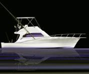
Source: Cavileer BoatworksThe Cavileer 44 hull was designed by Donald L. Blount and Assoc. for minimal draft in near-shore shallow water but fast cruising in rough seas offshore. A detailed weight estimate and laminate design helped optimize hull weight.
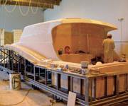
Source: Cavileer BoatworksCavileer technicians lay up the Cavileer 44 hull mold on the plug, using precut materials in foreground.
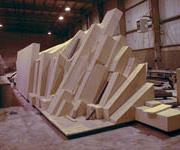
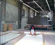
Source: DLBAFoam blocks are adhesively bonded to the hull plug's steel structure, prior to machining.
Source: DLBAThe deck plug after machining, but before surface coating is applied.
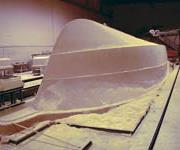
Source: DLBARobotic heads complete the machining of the hull plug.
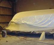
Source: DLBAThe hull plug was covered in shrink-wrap plastic and trucked to Cavileer's facility in New Jersey.
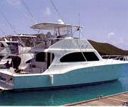
Source: Cavileer BoatworksA sportfishing powerboat has specific requirements for hull and deck design to ensure open water performance.
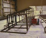
Source: DLBAThe steel support frame takes shape for the Cavileer 44''s hull plug.
According to the National Marine Manufacturers Assn. (NMMA), approximately 300,000 small powerboats were produced in the U.S. in 2003, with a total value of about $9 billion (USD). The vast majority of those vessels were made with composite materials, because of composites' quality, durability and relatively low cost compared to competing aluminum and wood. But the designs, methods and materials used in composite boat construction vary widely, from hand layup of advanced fibers for specialized racing models (for example, see CT August 2003, p. 44) to almost completely automated closed-mold processing for high-volume production, such as Genmar's VEC Technology, (CT November/ December 2000, p. 34).
How does the boatbuilder determine which materials and laminate schemes to use? What dictates the boat's design, tooling and fabrication methods? What does it really take to conceive of and produce a composite vessel with particular performance requirements for a particular market segment? In the following case study, CT delves into the design of the Cavileer 44, a 13m/44-ft "sportfish convertible" power fishing boat manufactured by Cavileer Boatworks (Lower Bank, N.J., U.S.A.). The boat's designer, naval architect firm Donald L. Blount and Assoc. (Chesapeake, Va., U.S.A.), tooling designer DLBA Robotics Ltd. (Chesapeake, Va., U.S.A.), and Cavileer's composites production experts reveal the essential principles of boat design. Several other marine composite experts weigh in, as well.


Boatbuilding Basics
"The first thing that has to be defined is how the yacht will be used," says Donald L. Blount and Assoc.'s designer Chris Swanhart. "A fishing yacht, a cruiser or a fast offshore racing boat all have different design requirements."
For starters, a sportfish yacht has unique features that set it apart from other types of vessels. Intended for the pursuit of trophy fish like marlin and tuna, it has an open cockpit large enough to accommodate several crewmembers and a "fighting chair," in which the angler sits. The chair requires extra structural support because it supports the angler's large fishing rod. To spot fish at a distance, the boat also needs a high "flybridge." It requires sufficient power for fast but comfortable cruising in offshore saltwater, yet must also maintain consistent, slow trolling speeds. Additional requirements include cabin accommodations that are comfortable, but not necessarily palatial, and lots of storage for gear, ice and fish.
The ideal size of the cockpit takes into account the size of the fighting chair and the distances required to maneuver around it, as well as sufficient space for gear. This results in a figure for the boat's overall width, or beam. Since a typical ratio of beam to length is about 33 percent, this defines the boat's overall length. "The 33 percent number is not a hard number -- it varies depending on the requirements of the owner," Swanhart explains. "For smaller boats -- less than 13.7m/45 ft in length -- the beam ratio has increased slightly in recent years to allow slightly larger cabin accommodations."
With overall dimensional estimates and a general hull form in mind, the designer's next step is a comprehensive weight estimate. An itemized list of all vessel components and their weights is drawn up, including the engines, electrical systems and interior accommodations as well as the composite hull, deck and remaining structure. While considered tedious, the estimate is essential to ensure that the design can meet speed goals with an acceptable draft (the hull depth in the water). Weight location also is key, because it affects the longitudinal center of gravity and hull performance, says Swanhart.
Naval architect Jay Miner of Delta Marine Industries (Seattle, Wash., U.S.A.) says that, for Delta yachts, at least 20 percent of the vessel's total weight is in the hull, so the best opportunities for managing weight to ensure performance can be found in fine-tuning the hull's composite laminate design. "The easiest pound to take out is the one that you never really needed in the first place," he explains. "Good engineering up front eliminates the second-guessing during layup."
The boatbuilder's fabrication process also plays a role in the weight estimate, notes marine designer Andre Cocquyt (GRPguru.com, Stuart, Fla., U.S.A.). To illustrate, he describes a boatbuilder who once weighed each of the several hulls built per week at his facility and found that they varied by nearly 10 percent -- as much as 900 lb -- in a roughly 10,000-lb structure. "The laminate design has to be very specific and resin use must be controlled as much as possible to achieve the ideal glass-to-resin ratio," he points out.
Once the target weight is determined, hull loads can be defined. This enables completion of the "scantling" design, or the layout of the boat's structure. Scantlings, which include the number and position of the stringers and bulkheads as well as the composite fiber architecture and laminate thickness, increase in complexity and importance as boat size, speed and performance requirements increase, says Swanhart. Documented calculation methods and test data for scantlings can be obtained from classification societies such as the American Bureau of Shipping (ABS) and Det Norske Veritas (DNV). However, Swanhart points out that most privately owned small fishing boats like Cavileer's aren't classed, so those methods aren't always used as the design basis, although they normally are considered. For his designs, he uses a series of in-house-developed spreadsheets to calculate loads, deflections and factors of safety to optimize the composite structural design.
Swanhart and Cavileer president John DiDonato agreed that the 44, powered by two reliable Caterpillar 700-hp diesel engines, should be able to cruise at 35 knots/40 mph. To maintain that speed in open water, the boat would need a planing hull, a structurally robust V-shape capable of withstanding not only the hydrostatic loads generated by the water it displaces but the significant hydrodynamic forces generated by impacts with heavy waves, as well. "A V-shape offers the smoothest ride in rough waves, because it tracks well and it helps to reduce vertical acceleration when the boat comes down in the water," explains Swanhart.
The design assumed local hull pressure loads of 3G vertical acceleration -- considered fairly high but plausible in open water at speed. Bulkhead and stringer locations were arranged accordingly to optimize useable engine room and living quarters without compromising the vessel's structural integrity. While torsional loads were certainly considered, Swanhart explains that at the design speed, for boats less than 30.5m/100 ft long, they aren't as critical as local hydrodynamic pressures. Loads generated by water inadvertently entering the cockpit also were calculated, and generously sized scuppers were strategically designed to ensure good drainage.
The final hull shape was developed with a surfacing software package called MultiSurf by AeroHydro Inc. (Southwest Harbor, Maine, U.S.A.). Rhino software from Robert McNeel & Assoc. (Seattle, Wash., U.S.A.) was used to develop the more intricately shaped deck parts.
Laminate Development And Material Selection
With the design factors set, Swanhart was ready to specify the materials and ply schedule. As one of a group of designers who prefer not to use wood-cored laminates below the waterline, he went with a solid fiberglass laminate for the wetted hull, using an industry-standard factor of safety of approximately 2. The decision has practical benefits, he points out, because solid laminate is easier to lay up than a cored laminate in a highly contoured V-hull keel mold. Longitudinal stringers were specified in closed-cell foam, overwrapped with hull laminate plies to form part of the hull structure.
Because the hull design was stiffness-driven, extra material was required to ensure that the solid laminate schedule would meet deflection targets. "Scantling design is essentially a spiral process," explains DLBA's Doug Blount. "You input the structural forms and materials, knowing the overall weight limits you have to meet and the loads you're designing to, and oftentimes the materials and structural framework change slightly to make all the pieces fit together."
Above the waterline, composite components were designed as sandwich panels cored with end-grain balsa from Alcan Baltek Corp. (Northvale, N.J., U.S.A.). Floor panels in the cockpit and below decks were specified with thermoplastic polyethylene honeycomb supplied by Nida-Core Corp. (Port St. Lucie, Fla., U.S.A.) to take advantage of its lower weight and better sound damping characteristics. Though more expensive in terms of material and repair cost, says Blount, cored sandwich panels have numerous advantages in boat construction, including lighter weight when compared to a solid laminate of equal stiffness. A cored sandwich also possesses superior impact and damage performance and provides better sound and vibration damping. During fabrication, however, good skin/core bonding is critical to develop the expected structural performance.
The transition point between the cored sides and the solid laminate hull, known as the "chine" area, posed a difficult design challenge. "The chine joint tends to want to act as a hinge, as the bottom of the boat flexes inward and the sides flex inward due to the external pressures," says Rob Schofield (Robert A. Schofield, Naval Architect, Melbourne, Fla., U.S.A.). "You don't want movement there, and the fabricator has to add extra laminate to resist these rotational stresses."
To counteract the "hinge" effect, Swanhart's design bevels the core edge at the chine joint, then laps the side skin plies on either side of the core into the bottom laminate, and laps the bottom laminates up the sides, to form a "taper out" structure. Schofield agrees with Swanhart's method, noting that a good rule of thumb for taper distance is 25mm/1 inch per ply.
To join the deck parts to the hull, Cavileer specified a "sandwich fit" joint, where flat edge flanges fabricated on both the deck and hull fit together, are filled with a watertight adhesive, then through-bolted with metal fasteners. An alternative approach is a "shoebox" joint, with a flange on the deck fitting over the hull like a box lid. In both cases, fasteners pass only through the flange and not through the cored laminate, says Swanhart. For through-deck attachments, like those supporting the tall aluminum fish-spotting tower, Swanhart added extra buildups to support and hold the fasteners.
Other design tweaks included extra reinforcement buildups around the strut that supports the propeller shaft as well as the rudder attachment, because of the extra loads in those areas. While unidirectional carbon fiber may be used in a few key locations, like the top surfaces of hull stringers for low-weight stiffness, Cavileer's design did not require it. Tough aramid fiber, often in a woven aramid/glass hybrid form, is used in some designs for the outer hull laminate to improve damage resistance, says Swanhart. In the case of the Cavileer 44, a woven fabric backed with chopped strand mat was selected as the primary laminate material.
"Many factors affect the exact choice of material," he states. "The availability, the price and the builder's familiarity with the product all come into play."
New combination fabrics and multiaxials, typically in fiberglass, are constantly evaluated for the company's designs. They may be specified for laminates, depending on price, because in many cases they can deliver desired strength at lower weight, by increasing the fiber-to-resin ratio. But, Schofield cautions that substitution of newer, higher- performing materials, such as multiaxials, may tempt designers to reduce laminate thickness to the point where excessive flexibility could result in cracking. "The outermost plies work the hardest and should have the highest strength," he explains. "Inner plies are less highly stressed and can be materials like mat or less-expensive bulker plies."
Tooling Considerations
With the design and materials in place, the Cavileer 44 tooling was recently completed. DLBA Robotics followed tradition and created male plugs for the hull and deck, from which female fiberglass molds are currently being produced by Cavileer. Blount points out that while it is possible to make hulls directly in a cold molding process, a fiberglass mold has a longer life and is much more suitable for a mass-production environment.
"For a prototype or one-off vessel, you can get away with jig frames, or a directly-machined female mold," he explains. "For the Cavileer 44, which is a production model, clearly both a plug and a mold were required."
The MultiSurf and Rhino design data were imported into SURFCAM software from Surfware Inc. (Westlake Village, Calif., U.S.A.) to develop the CNC tool paths, which control the company's two 7-axis robotic cutting machines (see CT, November/December 2000, p. 48). DLBA's robotic machining center has a work envelope of 25m by 4.6m by 3.2m high (82 ft by 15 ft by 10.5 ft), and the robots move along floor tracks for maximum flexibility.
DLBA used rigid, low-density, closed-cell polyisocyanurate foam adhesively bonded to an interior steel support structure to produce the Cavileer 44 hull, deck and flybridge plugs. Polyisocyanurate foam is physically and chemically compatible with styrenated resins. Easily machinable, the foam also can withstand the exothermic heat of composite cure during mold production. But as Blount points out, no one material meets every situation, and certain manufacturers will request other materials, such as tooling putties that can be sprayed or troweled. The choice of materials depends primarily on the final manufacturing process and number of parts planned. Cost, durability, storage situations (inside under cover or outside exposed to weather) or even humidity fluctuations at the facility also may play into the plug material selection.
Once machined, the foam was covered with one ply of fiberglass chopped strand mat, to protect the foam and the plug shape. The mat also provides a bonding surface for the subsequent coat of filled polyester tooling putty, typically Polyfair T27 supplied by SP (North America) of Burlington, Ontario, Canada. The cured putty surface then was machined to final dimension. DLBA gave the machined plugs a final coat of Duratec primer from Hawkeye Industries Inc. (Marietta, Ga., U.S.A.). The plugs were shipped by truck to the builder's boatyard, fully enclosed in plastic shrink-wrap, with their steel frames firmly strapped to the truck bed.
Culmination Of A Rigorous Process
Cavileer is currently fabricating molds on the plugs, using a combination 0/90 woven E-glass fabric backed with a 0.75-oz chopped strand mat, manufactured by Saint-Gobain BTI Inc. (Brunswick, Maine, U.S.A.) and supplied by marine distributor Mahogany Co. of Mays Landing Inc. (Mays Landing, N.J., U.S.A.). Eight to ten plies will make up the final tool laminate, for a total cured thickness of about 1 inch. Backup structure for the roughly 10,000-lb hull mold will consist of wood and a steel base cradle to enable transport around the boatyard.
Cavileer's DiDonato says that molds should be completed by the end of the year and layup of the first boats will begin shortly thereafter. He expects that 6 to 12 of the $750,000 boats will be fabricated each year and that the model could be offered for as long as 10 years.
Parts will be fabricated with a low-VOC gel coat supplied by Interplastic Corp. n Thermoset Resins Div. (St. Paul, Minn., U.S.A.) and a skin coat consisting of 1.5-oz chopped strand mat to prevent any print-through from the woven fiberglass. Technicians are trained in layup procedures that ensure complete wetout of the skin coat, which prevents water ingress and subsequent hull blistering. Approximately eight plies of a heavier woven E-glass/mat combination material will make up the solid hull laminate, and sandwich panel skins will be four to five plies thick, on both sides of 18.75 mm to 25 mm (0.75-inch to 1-inch) thick end-grain balsa. Cavileer uses general-purpose vinyl ester resin from Ashland Specialty Chemical Co., Composite Polymers Div. (Columbus, Ohio, U.S.A.). Parts will be vacuum-bagged and allowed to cure at room temperature
DiDonato says Cavileer likes building with hand layup methods, which are a selling point in the semi-custom yacht market. One reason is that all materials, including the reinforcements and cores, are pre-cut and kitted in boxed sets by distributor Mahogany, which greatly simplifies the fabrication process and makes the parts much more consistent than in the past, explains DiDonato. He will likely not go to a closed infusion molding process anytime soon.
"The kits have improved our quality control, they speed the process and we save time and money," he states. "We know exactly how much weight is going in, which makes the final product consistent with the design."


.jpg;maxWidth=300;quality=90;format=webp)


Related Content

RUAG rebrands as Beyond Gravity, boosts CFRP satellite dispenser capacity
NEW smart factory in Linköping will double production and use sensors, data analytics for real-time quality control — CW talks with Holger Wentscher, Beyond Gravity’s head of launcher programs.
Read More
Materials & Processes: Tooling for composites
Composite parts are formed in molds, also known as tools. Tools can be made from virtually any material. The material type, shape and complexity depend upon the part and length of production run. Here's a short summary of the issues involved in electing and making tools.
Read More
Plant tour: Albany Engineered Composites, Rochester, N.H., U.S.
Efficient, high-quality, well-controlled composites manufacturing at volume is the mantra for this 3D weaving specialist.
Read More
Materials & Processes: Fibers for composites
The structural properties of composite materials are derived primarily from the fiber reinforcement. Fiber types, their manufacture, their uses and the end-market applications in which they find most use are described.
Read MoreRead Next

Refurbished Einstein yacht demonstrates innovative composites repair and redesign
Years of creative engineering work went into resurrecting the composites-intensive IMOCA 60 racing yacht — with award-winning results.
Read More
World’s largest center console with single-skin hull
Navy RHIB concept goes commercial in the new HydraSports Custom Sueños high-performance offshore fishing boat.
Read More
CW’s 2024 Top Shops survey offers new approach to benchmarking
Respondents that complete the survey by April 30, 2024, have the chance to be recognized as an honoree.
Read More