
Testing the crashworthiness of composite structures
Dr. Donald F. Adams examines automobile crashworthiness, noting popular crashworthiness test methods for composites, and points out the lack of, and current progress toward, standardized testing for composite crash structures.
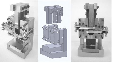
Fig 1: Current University of Utah flat coupon crashworthiness test fixture. Source: Don Adams
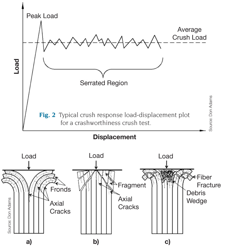
Fig. 3: Crush failure modes: a) fiber splaying, b) fragmentation, c) brittle fracture. Source Don Adams


Crashworthiness is the ability of a structure to absorb impact energy in a controlled manner so the contents of the structure survive the impact. Survival is governed by the deceleration forces induced during impact. Schoolchildren are often asked to design a package that will protect an egg dropped from a height. This popular science project is one example of designing for crashworthiness. Configuring an automobile so the human occupants survive a crash is another, more important, example.
Crashworthiness is determined by the design of the structure and by the material from which it is fabricated. Ductile metals absorb the kinetic energy of impact by deforming. In contrast, most composite materials are not ductile. They are reinforced by relatively brittle fibers. Even if those fibers are contained by a relatively ductile matrix, a composite absorbs crash impact energy primarily by delaminating, or debonding, at the fiber/matrix interface and shattering into fragments — that is, by creating large amounts of new free surface area. Thus, the design challenge is to promote a controlled breakup of the composite structure. A successful composite design can achieve impact/energy absorptions much greater than can be had with metals.


Because it is the assembled structure that ultimately must perform in service, crash tests of the complete structure — for example, the total automobile — are the ultimate test. Obviously, such tests are expensive. As an economical prelude, subassemblies can be tested first; each individual subassembly can be evaluated for performance and then redesigned and retested, if necessary. But this level of testing can be preceded by much less expensive testing of small components and laboratory-scale test specimens to more directly evaluate the energy-absorbing capacity of the materials. It is this level that we will examine here.
The energy-absorbing capacity of composite materials, particularly glass- and carbon-fiber composites, has been studied for many years. However, standard test methods do not yet exist, so most of this testing has been comparative in nature. That is, an individual laboratory develops a particular test configuration and protocol and uses it to compare a variety of candidate composite materials. One popular example is subjecting a short composite tube to axial compression.
During the past few years, however, there have been focused efforts to develop standard test methods, specifically for quantifying the energy absorption capacity of the composite material itself. These methods have taken two primary forms, namely, the testing of self-supporting shapes and the testing of flat test coupons supported as required to prevent buckling. Both forms require a failure initiator or trigger designed into the specimen geometry to create local stress concentrations that initiate the crushing process. The trigger determines where the crushing failure initiates and propagates from, which is usually located at one end of the specimen.
Tubes are the most commonly used self-supporting shape. Angle and channel cross-sectional shapes and sine wave cross sections are less common. Obviously, the specimen geometry can influence the failure mode and the energy absorption; therefore, the shape must be standardized. But this has yet to be done. Shaped specimens are kept short so that gross (Euler) buckling does not occur during the axial compressive loading. Therefore, the specimen requires minimal lateral support. In fact, no special test fixturing is required. The specimen simply rests on a flat surface.
To avoid the influences of specimen shape, a more direct measure of the composite material’s energy-absorption capability is to subject a simple flat coupon to an axial compressive force. Gross buckling of the specimen must be prevented here, too, and this requires some type of antibuckling fixture. Unintentional reinforcement of the specimen, or other influence of the fixture on apparent energy absorption, must be minimized. This typically requires an unsupported length in the zone where the crushing occurs. The resulting debris accumulation must not interfere with subsequent crushing, so the fixture also should have an open design.
A number of flat-specimen test fixtures with general characteristics have evolved in recent years. An excellent review of these developments, with photographs and sketches, has been presented by Garner and Adams.1,2 An even more recent, detailed review of crashworthiness in general has been presented by Courteau and Adams.3,4 As is typical, each new development has tended to build on prior design features. An example of the current generation of fixtures is shown in Fig. 1. The thin, rectangular specimen is clamped above the unsupported test section and is loaded on its top edge. Crushing occurs at the bottom where the specimen contacts the fixture base. (Note the serrations at the bottom of the untested specimen in Fig. 1. This is one of several types of trigger geometries currently in use.) The clamps permit the user to open the fixture easily for specimen exchange and debris removal.
In a successful test, the various parameters are controlled so the desired failure is obtained; beyond the peak force at which crushing is initiated, a relatively constant crush force is maintained as the specimen progressively fails (shown schematically in Fig. 2). The total absorbed energy is represented by the area under this load-displacement curve and, thus, a constant crush force represents a highly efficient, energy-absorbing failure mode. But this total absorbed energy is a function of the total volume of crushed material. To directly compare one material to another, then, it is desirable to calculate the specific energy absorption (SEA). This is achieved by dividing the total energy absorbed by the specimen cross-sectional area, crushed length and material density. Typical desired failure modes are indicated in Fig. 3. In all cases, the goal is to create as much new free surface as possible in the crush zone.
Based on the extensive research conducted in recent years, there is now a strong need to standardize crashworthiness testing. The development of test methods that use both self-supporting shapes and fixture-supported flat specimens has advanced to the point where one or both approaches could be standardized. Standardization would encourage the focused use of these specified test methods and reveal any remaining deficiencies in the current approaches.
Wyoming Test Fixtures Inc.
References:
1D.M. Garner and D.O. Adams, “Test Methods for Composites Crashworthiness: A Review,” Journal of Advanced Materials, 40(4), pp. 5-26, 2008.
2D.M. Garner, Crush Testing, Characterizing, and Modeling the Crashworthiness of Composite Laminates, Ph.D. Dissertation, Department of Mechanical Engineering, University of Utah, December 2009.
3M.A. Courteau and D.O. Adams, “Composite Tube Testing for Crashworthiness Applications: A Review,” Journal of Advanced Materials, 43(2), pp. 13-34, 2011.
4M. A. Courteau, Investigating the Crashworthiness Characteristics of Carbon Fiber/Epoxy Tubes, M.S. Thesis, Department of Mechanical Engineering, University of Utah, December 2011.


.jpg;maxWidth=300;quality=90;format=webp)


Related Content

JEC World 2022, Part 3: Emphasizing emerging markets, thermoplastics and carbon fiber
CW editor-in-chief Jeff Sloan identifies companies exhibiting at JEC World 2022 that are advancing both materials and technologies for the growing AAM, hydrogen, automotive and sustainability markets.
Read More
Protecting EV motors more efficiently
Motors for electric vehicles are expected to benefit from Trelleborg’s thermoplastic composite rotor sleeve design, which advances materials and processes to produce a lightweight, energy-efficient component.
Read More
CFRTP enables better, greener smartphones
Carbon Mobile’s “monocoque” design eliminates separate case, cover and frame, better protects electronics and simplifies disassembly.
Read More
Composite prepreg tack testing
A recently standardized prepreg tack test method has been developed for use in material selection, quality control and adjusting cure process parameters for automated layup processes.
Read MoreRead Next

From the CW Archives: The tale of the thermoplastic cryotank
In 2006, guest columnist Bob Hartunian related the story of his efforts two decades prior, while at McDonnell Douglas, to develop a thermoplastic composite crytank for hydrogen storage. He learned a lot of lessons.
Read More
Composites end markets: Energy (2024)
Composites are used widely in oil/gas, wind and other renewable energy applications. Despite market challenges, growth potential and innovation for composites continue.
Read More
CW’s 2024 Top Shops survey offers new approach to benchmarking
Respondents that complete the survey by April 30, 2024, have the chance to be recognized as an honoree.
Read More