Structural health monitoring: Angling for the air
Structural health monitoring (SHM) systems for composite aerostructures have been slow to deliver on their promise, but a system developed by Luna Technologies (Roanoke, Va.) is on a glide path to implementation on in-service aircraft
In development for more than a decade, structural health monitoring (SHM) systems for composite aerostructures have been slow to deliver on their promise — they’re perpetual next-generation technologies. The premise of SHM is conceptually simple: integrate a series of sensors into composite laminates and other aerostructures to detect damage that might lead to failure of the structure and then alert (electronically, in real time) an onboard or ground-based crew to the type and location of the damage. In the aerospace world, however, no technology, no matter how straightforward, is speedily adopted. Every resin, fiber, adhesive, manufacturing process and SHM system, if it is destined to fly, must endure a rigorous testing and qualification process that makes speedy implementation impossible
Into that kind of heavy head wind Luna Technologies (Roanoke, Va.) is attempting to fly its SHM technology to market. Nonetheless, the company says it’s making substantial headway and expects, eventually to, implement it on a flying aircraft.
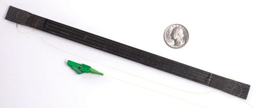
Working from technology developed at NASA Langley (Langley, Va.), Luna manufactures a dynamic distributed sensing system that uses the Rayleigh scatter of unaltered optical fiber as the sensor. With measurement rates of up to 100 Hz, cost-effective fiber sensors and significantly reduced installation time compared to equivalent foil strain gauges, this technology is designed to obtain dynamic strain data over a continuous object.
Rayleigh scatter is the light reflected from minute imperfections in an optical fiber. The scatter amplitude as a function of distance of a fiber is a unique, repeatable property of that fiber. A continuously tunable laser is used to spectrally interrogate the fiber. The reflected light from the scatter elements is then detected, demodulated and analyzed. Because the optical path difference between the reference reflector and each scatter reflection is different, the reflected signal from each scatterer is modulated by a unique frequency that is directly dependent upon the scatterer’s location in the fiber. As a fiber is subjected to environmental factors such as temperature or strain, the fiber is stretched or compressed, modifying the spacing of the scatter pattern and, thereby, its spectral response. When measured, this spectral change can be interpreted to determine the applied stimulus.
Mark Froggatt, Luna’s chief technology officer and developer of the company’s sensing technology, says optical fiber offers several advantages, including a relatively low cost (~$10/m), light weight, easy integration into composite structures and the ability to precisely measure temperature and strain at hundreds of points per meter of fiber.
Froggatt says Luna is attempting to get its technology accepted for use on flying aircraft. The starting point in this effort is implementation in design, test, verification and load frame testing, where Luna’s sensors replace foil strain gauges and the myriad wires that accompany them. Further, he notes, foil gauges typically fail at a few thousand microstrain, a value that optical fiber can easily exceed.
Dawn Gifford, Luna’s head of technology development, says the biggest advantages of the company’s fiber is easy integration with a composite structure and the ability to precisely detect and locate damage. “We’re going to sense whatever strain that fiber is experiencing at that location,” she says, adding, “We can detect the amount of strain around each defect.”
Real-world test
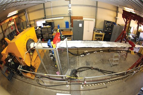
In an effort to prove that, Luna conducted a series of tests on a 9m/29.5-ft wind blade with carbon fiber spar caps, designed by Sandia National Laboratories (Albuquerque, N.M.) and manufactured at TPI Composites (Warren, R.I.). The blade featured intentional defects cast from resin prior to layup and introduced into the spar cap region of both the high-pressure and low-pressure sides of the blade at three span-wise locations. The wave height of all three defects was 3 mm/0.12 inch. Optical fibers were embedded in four layers of the composite structure. In all layers the fiber was routed in a straight line passing through points 2.54 cm/1.0 inch inboard of either end of the three defects. At approximately 1m/3.3-ft intervals, the fiber was woven into the composite material to maintain its position relative to the structure during the manufacturing process.
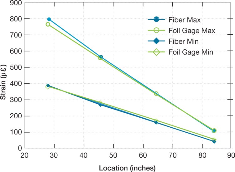
Following manufacture in Rhode Island, the blade was shipped to the National Wind Technology Center (NWTC, Boulder, Colo.) for additional instrumentation and pull, fatigue and property testing. In addition to the embedded fibers, optical fibers were bonded to the blade’s surface in areas of high and low pressure along its length. The fibers were offset from the spar cap centerline to coincide as closely as possible with foil gauges located on the centerline. Froggatt says the sensors not only pinpointed developing damage but also accurately predicted which load location would fail first.
“We want to succeed in the labs first, and then move out with the aircraft and into the air,” say Froggatt, noting that Luna also has placed its sensing technology in several military and commercial aircraft testing programs. Here, he notes, aircraft designers typically know what parts of the composite aerostructure are most susceptible to potentially damaging forces and, therefore, will place optical fiber selectively to monitor these regions more closely. In the air,
Luna’s system could be employed in either of two ways, says Froggatt. One way is to aggregate strain data from sensors via the company’s software and route it directly to the cockpit for flight-crew oversight. The other way is to aggregate and store data that could be accessed and assessed by maintenance crews on the ground between flights.
When could we see functional SHM systems on a flying aircraft? Froggatt and Gifford can’t say, but they see their recent progress and test results as promising: “Over the last few years, it has matured to become a very compelling technology,” says Froggatt.
Related Content
Scott Bader acquires Satyen Polymers, enhances commitment to Indian customers
Under the agreement, India-based Scott Bader Pvt. Ltd. will assume responsibilities for direct sales and marketing for all resin and gelcoat products, bring composites and adhesives to Indian market.
Read MoreMaterials & Processes: Tooling for composites
Composite parts are formed in molds, also known as tools. Tools can be made from virtually any material. The material type, shape and complexity depend upon the part and length of production run. Here's a short summary of the issues involved in electing and making tools.
Read MoreEpoxy-based structural film adhesive intended for aerospace, MRO
CAMX 2023: Park Aerospace is presenting its new aerospace-grade film adhesive material Aeroadhere FAE-350-1, in addition to other product offerings intended for aerospace, defense and spacecraft.
Read MorePark Aerospace launches aerospace, MRO structural film adhesive
Aeroadhere FAE-350-1 is a curing epoxy formulation designed for composite, metal, honeycomb and hybrid applications.
Read MoreRead Next
Composites end markets: Energy (2024)
Composites are used widely in oil/gas, wind and other renewable energy applications. Despite market challenges, growth potential and innovation for composites continue.
Read MoreFrom the CW Archives: The tale of the thermoplastic cryotank
In 2006, guest columnist Bob Hartunian related the story of his efforts two decades prior, while at McDonnell Douglas, to develop a thermoplastic composite crytank for hydrogen storage. He learned a lot of lessons.
Read MoreCW’s 2024 Top Shops survey offers new approach to benchmarking
Respondents that complete the survey by April 30, 2024, have the chance to be recognized as an honoree.
Read More






.jpg;maxWidth=300;quality=90)


