
Small-scale blade manufactured via bladder molding
High-compression bladder molding and modular tooling prove cost-effective for manufacture of small wind turbine rotor blades.


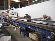
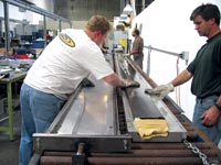
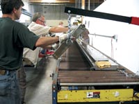
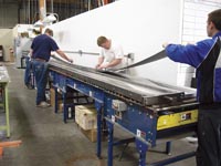
Source: AASITechnicians move the top section of the two-part blade mold into position, with the aid of two gantry cranes (one is visible at left.).
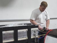
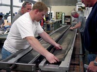
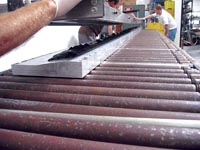
Source: AASIThe mold is loaded into the press. Air pressure is supplied to the bladder and the air spring, which has lifted the lower platen and closes the mold. The air spring hose is at shop pressure and the bladder is regulated to 65 psi.
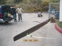
Source: AASIAASI principal Nancy Waterman and Quatro engineers prepare for blade deflection test. The load is applied at 120" from the root end. Deflection is measured along the scribed line on the pavement.
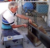
Source: AASIAASI principal Bill Leighty attaches a blade to a fixture in preparation for deflection testing.
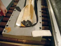
Source: AASIKen Gamble and Jason Nelson examine the surface finish of the part. The bladder and valve are visible in the foreground.
Source: AASIJason Nelson lays up root box ply group, the last and shortest group. Note the tapered tips at the drop off of each ply group.
Source: AASIThe glass and carbon layup is tucked around the latex bladder. A carbon wrap is fashioned for the tip. Tape holds the laminate closed over the bladder temporarily.
Source: AASIThe mold halves are closed. Attention is paid to aligning the pins in one mold half with their corresponding holes. A combination of round and diamond shaped pins are used to prevent rotation but allow for thermal growth.
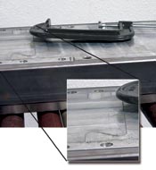
Source: AASIA closeup shows the modified dovetail joint Quatro used to join sections of the mold.
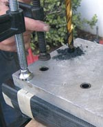
Source: AASIHoles in the root box end were drilled on a drill press and located with a drilling fixture. The woven fabric visible in the root box area for this pre-prototype was not used on actual field-tested parts.
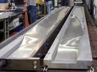
Source: AASIAluminum mold, CNC-machined in sections, assembled and polished. Joint lines are not visible.
Source: AASIThe top half of the mold is lifted off the part and tilted over after cure.
Source: AASIFull length base ply group is laid into mold.
Though the trend in wind energy today is toward more efficient energy generation through larger turbines with longer blades, organizations such as the American Wind Energy Assn. and the U.S. Department of Energy (DoE) also are working to help realize the potential for small wind turbines, with outputs of 100 kW or less. In April 2003, the DoE's Office of Wind and Hydropower announced its intention to fund small wind turbine hardware development projects that have the potential to improve the cost, reliability, and performance of small turbines for grid-connected applications, i.e., residential and small business uses, at low wind speed regimes. The goal was to achieve by 2007 the level of cost-effectiveness in Class 3 wind resources that can be achieved in Class 5 resources. The DoE defines Class 3 winds as those averaging 5.35 m/sec (12 mph) at an elevation of 10m/32.8 ft above ground level. Class 5 winds average of 6.2 m/sec (14 mph) at the same elevation. Since turbines optimized for Class 3 winds have a higher ratio of turbine swept area to drive train power rating than do turbines optimized for more energetic wind regimes, blades could account for a larger fraction of total wind turbine system capital cost.
In September of 2003, Alaska Applied Sciences Inc. (AASI, Juneau, Alaska) was awarded a DoE grant for its proposal to explore high-compression bladder molded prepreg (HCMBP) as a low-cost blade manufacturing technique. AASI owns 14 50-kW turbines on San Gorgonio pass near Palm Springs, Calif., which the company intended to use for the field testing of the HCMBP blades. California leads the United States in generation of electrical energy with wind turbines. In 2003, wind farms on its major mountain passes operated more than 11,000 turbines, running the gamut in power output from 50 to 1,500 kilowatts (kW), with approximately 2,043 megawatts (MW) of cumulative capacity -- about one third of the total U.S. capacity (6,374 MW) at that time. Although small turbines contribute a fractional percentage of the overall power output, they make up over one-third of the number of turbines on the passes.


Quatro Composites Inc. (Poway, Calif.) was selected to develop the bladder molding manufacturing process for the blades. Quatro co-owners Ken Gamble and Doug Roberts specialize in the development and production of bladder and compression-molded prepreg parts and assemblies in several markets, including medical, recreational and space. They were asked to supply tooling and dedicated curing equipment and to manufacture as many sets of blades as the funding would allow.
Quatro began the project with a blade design supplied by Salter and Assoc. (San Diego, Calif.). Ed Salter had previously designed (and owned the company that in the mid-1980s built) the wind turbines now used in AASI wind farms, and made not only the original blades for AASI turbines but also a precursor to the blade Quatro was about to build.
Salter's design called for blades 5.71m/18.75-ft long, varying in width from 30 cm/12-inches at the widest point to 15 cm/6 inches at the root and 10 cm/4 inches at the tip. Designed to withstand a wind load of 58 m/sec (130 mph), which translates into a load of approximately 727 kg/1600 lb, each blade would have an 8° twist from root to tip and a tapered wall thickness, 1.5 mm/0.060 inches at the tip gradually thickening to 9 mm/0.30 inch at the blade root. The turbines the blades were designed for are downwind turbines, which means that the blades deflect away from the tower under wind load and rebound back toward the tower at every pass through the tower shadow and during fault-response shutdown. During a fault-response or overspeed shutdown, the blades undergo an instant change in pitch while rotating, and the wind load on the blade is immediately eliminated. To keep the blades as flexible as possible (to minimize bending moments on the main turbine shaft and throughout the wind generator structure, yet also meet torsional requirements), the blade laminate for the first set of three blades consisted of one-third 0° and two-thirds ±45° unidirectional carbon fiber. When this set was field tested and determined to be stiffer than necessary, the second set was made with unidirectional E-glass replacing carbon in the 0° plies.
Quatro designed the blade's clamshell mold by first translating the CAD design file from Solidworks, the software used by Salter in the design process, into a Pro/ENGINEER file. (SolidWorks 3-D Design Software is written by SolidWorks Corp., Concord, Mass. Pro/ENGINEER is a software product of PTC, Needham, Mass.) Machine tool paths were generated for Quatro's CNC mill using Pro Manufacturing, the CAM portion of the Pro/ENGINEER software package. As is often the case, the translation step was more involved than anticipated, but nonetheless was completed in about a month, after which machining began. The 6.1m/20-ft long tool halves were milled from 6061-T6 aluminum in seven modular sections, which are joined together using modified dovetail joints. Since traditional dovetail, such as is seen in furniture, would be very difficult to machine, Quatro smoothed the sharp corners to make a joint resembling the outline of a jigsaw puzzle piece. The modular strategy kept costs down by enabling Quatro to fabricate the mold on a standard-sized mill, with standard-sized aluminum blanks. In addition, should design modifications be required at a later date, e.g., to change the length of the blade or modify the shape of the tip, the modular design also means that only some portions of the mold will have to be replaced.
After the tool segments were fabricated, they were assembled and the mold surface was hand polished to a high gloss, leaving the joint lines barely visible. The assembled mold weighs close to 341 kg/750 lb which creates the potential for considerable bending loads over its 609-cm/240-inch length. To prevent excessive loads on the mold's joints during lifting, a steel perimeter frame was built to support the assembled tool. Two gantry cranes were set up to lift and open or close the mold halves for layup, cure and disassembly, using chains that attach to lifting hooks on the mold frame. Yet, even with the steel framework present, the mold sags approximately 7 to 10 cm (3 to 4 inches) in the center, when supported at both ends.
In order to react the bladder molding pressure and supply heat to the mold, a 'fire hose" air spring press was custom-built to fit the mold. These presses are economical to build, and are designed with barely more daylight opening than the height of the mold and just enough frame stiffness to react the relatively low pressures that composite molders use. A 25.4-cm/10-inch lay-flat fire hose inflated to 655 kPa/95 psi is used to raise the lower platen of the press and keep the mold halves closed. The fire hose size and pressure along with the amount of daylight opening in the press must be taken into consideration so that the fire hose keeps the mold closed against the internal pressure of the bladder, but doesn't inflate too much and become round. This would reduce the contact area between the fire hose and the platen, causing a loss in mold closing force. The mold platens were fabricated from 19-mm/0.75-inch thick aluminum. Heat was supplied via programmable controllers to calorimetric rods embedded in the back surfaces of the platens.
The blade's laminate was built up in five groups of 12 plies each, using prepreg supplied by Aldila Inc. (Poway, Calif.). Each successive group had the same layup but a shorter length, ranging from the full length of 571 cm/225 inches down to 46 cm/18 inches. After each group was cut to shape and plied together, they were vacuum debulked for several hours to remove entrapped air. The tip end of each group (other than the full length base group) was tapered on each side to reduce stress concentrations at the ply drop off. To accommodate the bladder molding process, one half of the laminate was made net to the width of its mold, while the laminate for the other mold half was oversized, enabling technicians to wrap the edges over the bladder during layup. When the mold halves are joined, this ensures sufficient overlap at the junction of the two halves to provide adequate load transfer between the co-cured blade halves.
After the Quatro team had layed up the 12-ply prepreg stacks into each half of the mold, the bladder, coated with release, was put in place. Quatro uses custom-made latex bladders supplied by Latex Technology Inc. (LTI, San Marcos, Calif.). A bladder is formed by dipping a mandrel into liquid latex, allowing it to cool, and then removing it from the plug. Although the typical life of such a long bladder is only two to three parts, latex bladders are relatively economical and do not constitute a large part of the piece price. Because the part length was greater than that of LTI's dipping tanks, Quatro's Ken Gamble designed a proprietary telescoping mandrel which would expand as it was pulled out of the 122-cm/48-inch dip tank, bringing wet latex out of the tank to dry on the mandrel, continuing the process until the entire 6.1m/20-ft long bladder was fabricated. The finished bladder is about 1.5-mm/0.06-inch thick and has a valve mechanism fixed to the root end to inflate and deflate the bladder.
Next, the prepreg from the oversized laminate half was folded down over the bladder. A piece of woven fabric was folded over the tip of the bladder to enclose it, and extra tows of unidirectional carbon were placed in critical areas around the tip and trailing edges of the part so that the outermost fibers would be running parallel to the part edges. This improves edge cosmetics and makes it easier to sand the flash line.
At this point, the gantry cranes lifted one half of the mold into position over the over half and the mold was closed. Quatro used a combination of round and diamond-shaped pins to align the mold halves. The round pin fixes the mold in the x and y directions, but still allows rotation. The elongated diamond-shaped pins not only prevent rotation but also accommodate mold growth due to thermal expansion during the heated cure of such a long aluminum tool.
The tool was loaded into the preheated press and cured at a temperature of 140°C 285°F and a bladder pressure of 448 kPa 65 psi for 1.5 hours. According to Jason Nelson, the project's lead engineer, the mass of the mold was more than that of the platens, which made it difficult to heat the mold quickly and uniformly. "By starting the cure with the platens about 20° hotter than the final cure temperature, we were able to heat the mold up in about 15 or 20 minutes," he explains.
After cure, the blade was removed from the mold and the bladder was pulled out. Although there was concern that such a long bladder would not come out, it came out without problems. The blades were then ready for post-mold processing.
To prevent blade flutter during turbine operation, the design requires that the cross-sectional center of gravity be in front of the center of pressure, or no more than one quarter of a chord length away from the leading edge in the outboard half of the blade span. To accomplish this, a 287-cm/113-inch long leading edge D-spar (LEDS) was fabricated for the tip in an aluminum mold fabricated by Quatro. The LEDS was made with room-temperature-cure Co-poxy epoxy resin from Epoxical (S. St. Paul, Minn.) filled with steel shot and then poured into a piece of carbon fabric prepreg that had been layed up in the mold. Once the LEDS was cured, it was ready for incorporation into the blade.
"For the first set of blades, we tried a cocuring technique where we put the LEDS pieces into the mold and cured the prepreg around them," notes Gamble. To keep the bladder from tearing at the drop off of the LEDS, a piece of 10-lb polyurethane foam was molded to the same shape as the LEDS and was layed up back-to-back with the epoxy/steel shot LEDS in the blade tool. "But this approach was not acceptable," he notes. "Even though we added a buildup of extra tows of carbon at the edge of the LEDS to make a more gradual transition from solid section LEDS to thin wall of the blade, there were compaction and wrinkling problems at the drop off where the bladder couldn't reach into the radius." For the second set of blades, the cured LEDS was inserted into the open end of the blade and potted into position with the same epoxy resin used to make the LEDS. This improved compaction of the blade skin and enhanced surface cosmetics.
Next, the root box of each blade was drilled for the rotor hub mounting bolts, and the inside of the root end was potted with aluminum-filled epoxy to withstand crush loads that the blades will encounter when mounted to the hub. To keep epoxy from filling the holes during the potting process, Quatro temporarily installed release-coated bolts.
Every blade is deflection-tested, using a low-tech yet effective method. The root end of the blade is secured to a steel frame bolted into the concrete of the parking lot. A steel cable and a load cell are attached to a pickup truck at one end and to the blade at the other end, 100 inches from the root. A ratcheting wrench is used to slowly and steadily increase the tension of the steel cable, while the load cell provides a real-time readout of the load, and the pickup truck acts as an anchor. Deflection is measured using a plumb bob that hangs from the blade and traverses a measuring stick laid on the ground (see photo p. 37). For the initial destructive testing, the blade was deflected 72 cm/28.5 inches, as measured at a point 406 cm/160 inches from the root, and failed at a load of 514 kg/1130 lb. The nondestructive flap stiffness test, conducted on every blade in this initial stage of the project, calls for deflections to be measured at the tip and at 120 inches/305 cm from the root, with loads of 264 kg and 330 kg (120 lb and 150 lb), respectively. Deflections are measured and recorded, to be used in conjunction with data obtained in field testing. Torsional stiffness and resonant frequency data are also collected for each blade.
After deflection testing, the blades are prepped for painting. The parting line is sanded and smoothed, and small surface defects are filled. Then the blades are primed and painted white, using Sherwin-Williams 4800-series Prothane two-part linear polyurethane (The Sherwin-Williams Co., Cleveland, Ohio). Finally, the blades are tip weight balanced to within 20g/0.71 oz. The finished blades each weighed approximately 23 kg/50 lb before paint and hardware was attached, of which 7.7 kg/17 lb was the LEDS. As this article went to press, the second set of three blades had been mounted on one of AASI's California turbines for field testing, and design modifications had begun for the expected third set of blades.
After the third set of blades is made and field tested, Quatro will estimate the volume manufacturing selling price for this blade, which will be part of AASI's final report to the DoE. AASI principal Bill Leighty believes that this R&D project has proven that the HCBMP process is technically and economically attractive for blades 1.5m to 6m (5 ft to 20 ft) long. Smaller blades do not need the strength and stiffness of long fiber composites, and in longer blades, the requirement for internal rib stiffeners or foam may increase the cost of closed clamshell molding to a point where it is no longer competitive. But within its range, the method's advantages include a good surface finish, minimal flash line, a smooth trailing edge, efficient use of tooling and labor, minimal cleanup, good process repeatability and control of the blade weight and balance point. As a result, this quick, economical process, successfully employed over the years in many commercial products, is likely to find new application in the world of wind turbine blade manufacturing.


.jpg;maxWidth=300;quality=90;format=webp)


Related Content

Moving toward next-generation wind blade recycling
Suppliers, fabricators and OEMs across the composite wind blade supply chain ramp up existing technologies, develop better reclamation methods and design more recyclable wind blades.
Read More
Drag-based wind turbine design for higher energy capture
Claiming significantly higher power generation capacity than traditional blades, Xenecore aims to scale up its current monocoque, fan-shaped wind blades, made via compression molded carbon fiber/epoxy with I-beam ribs and microsphere structural foam.
Read More
Materials & Processes: Fibers for composites
The structural properties of composite materials are derived primarily from the fiber reinforcement. Fiber types, their manufacture, their uses and the end-market applications in which they find most use are described.
Read More
Materials & Processes: Fabrication methods
There are numerous methods for fabricating composite components. Selection of a method for a particular part, therefore, will depend on the materials, the part design and end-use or application. Here's a guide to selection.
Read MoreRead Next

Anisotropic wind blade design expected to reduce wind-energy costs
Deliberately unbalanced laminate produces smoother power input from adaptive wind blades
Read More
Carbon/glass hybrids used in composite wind turbine rotor blade design
As turbine blades grow to greater lengths, composite blade manufacturers take a long look at carbon/glass hybrids.
Read More
CW’s 2024 Top Shops survey offers new approach to benchmarking
Respondents that complete the survey by April 30, 2024, have the chance to be recognized as an honoree.
Read More