
RTM showcase: One-Piece Rudder
A transatlantic design team uses concurrent engineering to integrate rudder spars, ribs and skins in a single RTM cycle.

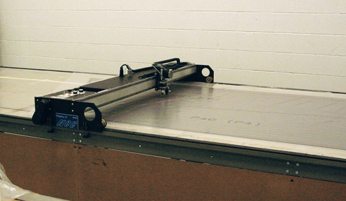
Step 3: Laminate reinforcements are cut out on this automated cutting table and then molded into net-shape preforms using ancillary tooling. Source: North Coast Composites
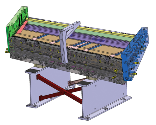
In preparation for mold manufacture, both primary and ancillary tools were designed, using CATIA V5. This screen shot shows a CAD model of the complete primary mold. Source: North Coast Composites
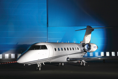
The new Gulfstream G250 business jet’s signature “Gulfstream T” tail structure features a one-piece composite rudder, codeveloped by OEM Israel Aerospace Industries and North Coast Composites (NCC, Cleveland, Ohio) and produced by NCC. Source: Israel Aerospace Industries
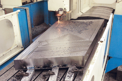
Step 1: CATIA design file data were used to program NCTM’s in-house CNC machining system to cut the tool faces. An in-process 4.5-ft by 10-ft (1.37m by 3.05m) rudder skin plate is shown. Source: North Coast Composites
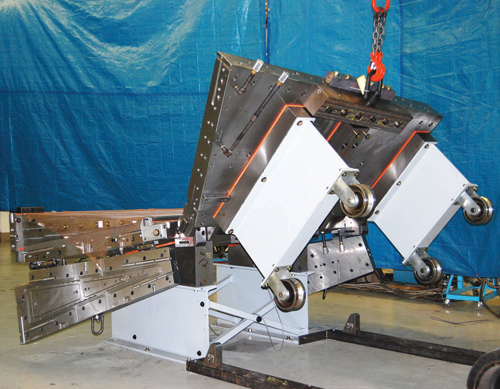
Step 4: In the completed primary mold, copper mesh lightning strike protection goes down first on the face of each mold half. After lay-up and insertion of rib preforms, located via interior tool details, the mold is closed, using an overhead hoist, and all bolts are tightened. Source: North Coast Composites
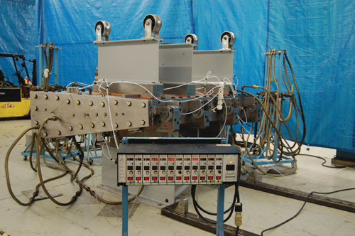
Step 5: The mold is shown prepped for injection with heated oil lines, thermocouple cables and vacuum lines attached and the mold process monitoring system (foreground) linked via an umbilical. Source: North Coast Composites
Step 2: This view shows the partially assembled primary mold. During assembly, precision-machined locators were machined and installed to ensure repeatable mold closure, cycle after cycle, without binding. Source: North Coast Composites
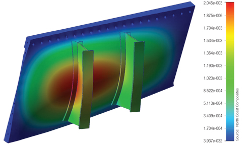
This screen shot of a rudder mold tool shows one stage of the deflection analysis completed during early mold design stages. NCTM determined to machine the primary tools from 6-inch/152.4 mm minimum-steel plate, a design decision that, under 240,000 lb (108,862 kg) of injection pressure (from injection), would limit mold deflection under pressure to less than 0.0025 inch (0.064 mm). Source: North Coast Composites
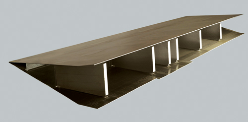
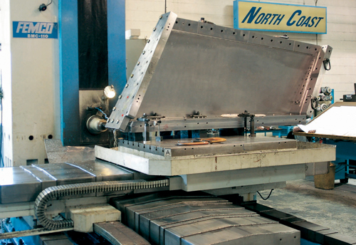
Step 6: The demolded rudder (shown here in vertical alignment and in end view) is 95 percent net-shape after demolding. The only postmold machining it requires is trimming of the three skin edges. Source: North Coast Composites


The new, super-mid-size Gulfstream G250 business jet rolled out on Oct. 6, 2009. Gulfstream Aerospace (Savannah, Ga.) and manufacturing partner Israel Aerospace Industries (IAI, Tel Aviv, Israel) developed the G250 in answer to its business jet customers’ requests for longer range (3,400 nautical miles at Mach 0.80), increased speed (Mach 0.85 maximum operating speed) and a larger cabin, without increasing hangar space requirements. The new model will eventually replace the G200, which was originally IAI’s Galaxy SPX. Gulfstream, a wholly owned subsidiary of General Dynamics (Falls Church, Va.), bought IAI’s Astra and Galaxy type certificates in 2001, then rebranded them, respectively, as the G100 and G200. IAI oversees manufacturing and assembly of the G100, the G200, and now, the G250 airframes, in Israel, while Gulfstream oversees completion, painting, marketing and product support in the U.S.
Scheduled for customer deliveries in 2011, the G250 is described as a “true Gulfstream,” thanks in part to its signature Gulfstream T tail (see photo, top right). A key part of the tail structure is its flight-critical one-piece composite rudder, which was codeveloped and is now produced by North Coast Composites (NCC, Cleveland, Ohio), a specialist in resin transfer molding (RTM) and vacuum-assisted RTM (VARTM). NCC offers single-source parts and tooling production with the assistance of its colocated partner company, North Coast Tool & Mold (NCTM).


The rudder, which measures 9.2 ft/2.8m long, 3.5 ft/1.1m wide, and 10 inches/25.4 mm thick, integrates ribs, spars and rudder skins, complete with lightning strike protection, into a co-molded, one-piece structure.
Working up a work cell
The project began when IAI solicited a bid from NCTM to supply not the part, but a turnkey RTM work cell for the rudder, which would be used for part production in Israel. IAI was impressed with North Coast’s combined RTM and tooling capabilities, and selected it for the work cell job from a list of six companies based variously in the U.S. and Europe. The initial idea of a one-piece rudder was conceived by IAI and further developed after about a year of concurrent engineering, a strategy for simultaneous — rather than the more typical linear or staged — product-design, tool-build and process-development sequence.
Because concurrent engineering is such a communication-intensive process, differences in time zones and RTM backgrounds became a challenge. “Just getting our process vocabulary and language in sync, to make sure we were all on the same page when we were hashing out process details took a lot of time and effort,” says NCTM president Rich Petrovich, noting that after IAI selected North Coast, “four to five of our guys sat down with three to four of their engineers on numerous occasions and just started firing through questions: ‘What part of this is going to be the hardest to achieve? What are the concerns? What will we need to work around? What are the cost and delivery targets, the materials, the tolerances?’” In the end, says Petrovich, this period of communication and data gathering consumed about five months. Only then did NCTM commit to build the turnkey work cell.
Specification & verification
Once the team agreed on a rough process definition, they worked on the specification for the tooling design. As project leader, NCTM’s Jay Evanovich faced several technical challenges. “We knew the outside of the tool would be steel, probably 6-inch [152.4 mm] minimum-thickness steel plate, to handle deflection issues, and we assumed the interiors would be aluminum to save weight and reduce cycle time.” However, the team soon learned that the cure temperature and time required for IAI’s specified resin system would prohibit the use of aluminum, so the tool’s internal details also would be made from steel. This change would increase mandrel weight from 400 lb to 1,200 lb (181 kg to 544 kg), and that, in turn, would alter the expected heating, tool handling and processing strategies.
The all-steel tool design was developed using CATIA V5 (Dassault Systèmes, Paris, France). The CATIA files provided the data for in-house precision CNC machining of the tool surfaces and details, using a Johnford Vertical Machining Center (VMC)-type CNC system made by Roundtop Machinery Industries (Shen Kang, Taichung, Taiwan). Deflection analyses verified that, at an injection pressure of 240,000 lb (108,862 kg), tool deflection would be limited to less than 0.0025 inch (0.064 mm), and also indicated that the tool could maintain the extremely tight part tolerance requirements: Ribs, spars and datum planes (horizontal skins) would be molded within 0.010 inch (0.254 mm) nominal, in a 38,000-lb (17,237-kg) tool where the part wall thickness would range from 0.039 inch to 0.125 inch (0.99 mm to 3.18 mm) over 120 ft² (11.2m²) of mold surface area.
Early flow analyses raised concern about injecting the IAI-specified high-viscosity resin over such a large surface area. In answer, NCTM incorporated 21 of its patented Directed Resin Injection & Venting (DRIV) inserts (see the article under "Editor's Pick's" in “Learn More,” at right) into the mold surfaces at strategic locations in both upper and lower tools so that complete wet-out of the fiber reinforcement could be achieved within the specified process window. The DRIV insert design permits air but not resin to escape the mold, reducing the likelihood of dry spots, yet leaves no tell-tale witness marks in the part surface. The insert strategy was proven effective in production of the first part, where resin flow matched that predicted by a flow analysis performed on a DRIV-equipped virtual tool.
Another level of complexity was added when NCTM suggested that a tremendous amount of production time and cost could be saved by integrating an L-shaped closeout on the end of each of the ribs into a single, comolded structure. Originally, the ribs were to be straight, molded separately, and then secondarily attached via a metal fitting to each rib. Although comolding the flange and rib added complexity to the tool, it saved production time and cost by eliminating secondary assembly. The resulting matched-metal, oil-heated resin transfer mold includes more than 65 steel tool details that are bolted together to form the surfaces for comolding the spars (complete with drain holes) and the ribs with their integrated L-flanges.
Taking time to save time
Given the mold’s complexity, postcure extraction of the complex part was not a trivial issue. Demolding would require almost complete disassembly of the tool. Numerous custom-designed precision locators were incorporated into the tool to ensure repeatable, exact placement of every steel detail, allowing technicians to disassemble the tool details during the demolding process and then reassemble them without sacrificing the dimensional integrity of successive parts.
Special attention also was paid to the safe, ergonomic handling of very heavy, large tool details. For example, specially designed hinges permit the multi-ton cover of the mold to be disengaged and rolled away easily from the lower half of the tool, facilitating layup of the part.
Petrovich points out that using oil to heat the tool offered processing economies. “It not only can heat, but if properly hooked up to a water tower or a chiller, the oil also will help to cool the mold, which reduces cycle time.” Further, an oil heating system could be used on other molds. In contrast, electric heating cartridges are dedicated to one mold and are of no use in the cooling process. Electrically heated molds require a second system for cooling. The production-ready tool would be outfitted with more than 30 umbilical cords, including oil feed lines, vent tubes, resin injection tubes and a series of O-rings to ensure vacuum integrity (see Step 5, at right).
When faced with the challenge of achieving such great precision with so many tool details, “concurrent engineering is a much slower development process,” Petrovich admits, “but it allowed us to continuously balance part design with tool design and handling issues.” More importantly, he points out that “the time spent in development was redeemed in the tool build because in-process inspections at the lowest detail level virtually eliminated the iterative fitting of tool details that is typically required.” In the end, the tool and its myriad details fit together perfectly with very little adjustment and practically no rework.
Tool proofs earn production go-ahead
Concerned about shipping a turnkey RTM work cell to Israel without proving it out first, Petrovich suggested to IAI that NCTM mold two tool proofs. IAI agreed, and sent at least 10 people on two different occasions to witness the tool-proof mold cycles. This well-advised step revealed inherent processing problems attributable to the resin and the physical size of the mold details, which NCTM then was able to solve before the mold was to be shipped. “We basically did all of the R&D trials on both the tooling and the parts production, which made it easier to manage problems with the tooling and make adjustments before they became issues in manufacturing,” Petrovich notes, adding, “We never had to ‘undo’ anything in the tooling because we had continuously ‘walked through’ the manufacturing process all along, first in analyses and then in actual prove-outs.”
The first step in tool-proof production was to release-treat the metal tools and details with Frekote 700-NC made by Henkel Corp. (Madison Heights, Mich.), selected because NCTM believes it is the least invasive for RTM processing in that it does not affect most resins. Meanwhile, plies of carbon- and glass-fiber noncrimp fabric (NCF) style reinforcements were cut on an automated cutting table from Carlson Design (Tulsa, Okla.) and kitted (see Step 3, at right).
The laminate schedules were tailored per structure, with ribs, spars and skins each having a unique layup. Ancillary tooling was used to premold the kitted layups into net-shape preforms, which then were placed in the RTM tool and held in precise position by the various steel tool details.
Copper mesh lightning-strike protection was incorporated into the skin layups, forming the first layer against the tool surface, and a completely molded-in conductive metal network for lightning-strike protection within the final skin. The mesh is very thin and requires delicate handling, especially on the 0.080-inch/2-mm radius trailing edge.
The tool was closed using special handling devices, parting line bolts were tightened and a vacuum check was performed, using a vacuum gauge and a 30-hp vacuum pump supplied by Kaeser (Coburg, Germany). After the tool was preheated for several hours, the high-temperature-cure epoxy resin was injected. After injection, technicians “burped” the DRIV vents to allow air extracted from the laminate to escape. The vents then were turned off, pressure was increased, and the vents were burped again. This sequence was repeated until all of the air was removed from the part. (The number of venting iterations and pressure increments were previously defined during mold process development.)
A datalogger was used to monitor and control 10 thermocouples; the device records heat and pressure for each part. The total injection/cure cycle lasted 13 to 16 hours due to the type of resin used, and the complete process of mold preparation, layup, shoot, cure and demold took roughly four work days.
After processing was completed, while the mold was still hot, mechanical details that were incorporated to accommodate the 0.25-inch/6.4-mm thermal expansion in the tool were adjusted so that the 38,000-lb/17,237-kg tool did not crush the 0.040-inch/1-mm thick part. The tool was cooled over the next six hours, followed by part extraction — a three-technician, five-hour process that requires disassembly of all the metal tool details. Because 95 percent of the details produce net-shape molded features, only the three skin edges require postmold machining.
Optimizing for production
One-piece rudders now are installed on aircraft and undergoing testing, and NCC is looking into process optimization. According to Petrovich, tool-proofing was a key to success: “Concurrent engineering is a balancing act between developing a mold that can be manufactured, developing a part that can be manufactured — or, in our case, refining the design — and developing the process. Although you do optimize a great deal, you can’t really fully optimize the process until after you have made a few parts.”
Notably, after IAI technicians viewed the tool-proof trials, the company decided not to ship the tool to Israel. Instead, IAI is subcontracting initial rudder production to NCC. Petrovich believes that temporary arrangement will soon become permanent. “We have made nine parts out of the final tool,” he reports, “and are now negotiating a work order for serial production on a volume basis.”


.jpg;maxWidth=300;quality=90;format=webp)


Related Content

Price, performance, protection: EV battery enclosures, Part 1
Composite technologies are growing in use as suppliers continue efforts to meet more demanding requirements for EV battery enclosures.
Read More
A new era for ceramic matrix composites
CMC is expanding, with new fiber production in Europe, faster processes and higher temperature materials enabling applications for industry, hypersonics and New Space.
Read More
PEEK vs. PEKK vs. PAEK and continuous compression molding
Suppliers of thermoplastics and carbon fiber chime in regarding PEEK vs. PEKK, and now PAEK, as well as in-situ consolidation — the supply chain for thermoplastic tape composites continues to evolve.
Read More
Plant tour: Joby Aviation, Marina, Calif., U.S.
As the advanced air mobility market begins to take shape, market leader Joby Aviation works to industrialize composites manufacturing for its first-generation, composites-intensive, all-electric air taxi.
Read MoreRead Next

New Approaches To Cost-effective Tooling
New methods, materials and philosophies add up to tooling innovations.
Read More
Composites end markets: Energy (2024)
Composites are used widely in oil/gas, wind and other renewable energy applications. Despite market challenges, growth potential and innovation for composites continue.
Read More
CW’s 2024 Top Shops survey offers new approach to benchmarking
Respondents that complete the survey by April 30, 2024, have the chance to be recognized as an honoree.
Read More