
Restoring a museum masterpiece with composites
Carbon fiber/vinyl ester reinforcement extends the structural life of architectural and art-world landmark.


As restoration steps proceeded (see image below), visible cracks in the paint coating often indicated cracking in the underlying concrete, which then required repair with new materials. Photograph by David Heald Photos copyright Solomon R. Guggenheim Foundation, New York
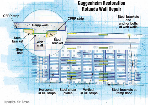
Illustration: Karl Reque
Source: Photos copyright Solomon R. Guggenheim Foundation, New York
Photograph by David Heald Photos copyright Solomon R. Guggenheim Foundation, New York
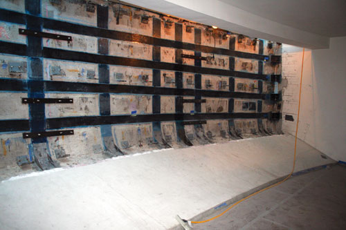
The restoration team devised a CFRP repair for the sixth floor rotunda wall that comprised vertical and horizontal strips, the layout of which (see below) was different for each of the 10 bays along the upward-spiraling 300-ft/91.4m walkway. Source: Photos copyright Solomon R. Guggenheim Foundation, New York
Design Results:
¤Carbon fiber strips restore tensile capacity to deterior-ating ramp wall yet meet architectural, aesthetic and preservation requirements.
¤Steel brackets restore continuity and load transfer from ramp wall to floor slab connection and through perpendicular web wall intersections.
¤CFRP and steel bracket system conforms to unique geometry, minimizes impact to architecture, meets 100-year service life requirements and enables project completion on time and under budget.


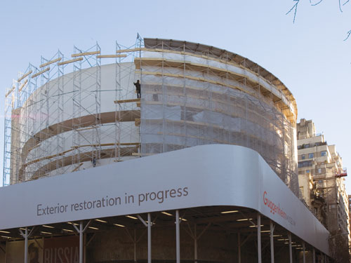
In 2005, a team of engineers, conservators and architects collaborated to extend the life of a Frank Lloyd Wright architectural masterpiece, New York City’s Guggenheim Museum, into the 22nd Century. An exhaustive 17-month analysis, including removal of 11 paint layers, laser surveys of surfaces, crack movement monitoring, and drilling for core samples of the original concrete, concluded that the museum, completed in 1959, was in good structural condition except for several issues identified in the sixth floor rotunda wall. A defect during original placement of the concrete caused discontinuities in the steel rebar on both the inside and outside faces of the wall. The restoration team had to devise a repair that would improve structural performance without changing the wall’s inherent construction or appearance. According to Glenn Boornazian, president of the team’s architectural conservators, Integrated Conservation Resources (New York, N.Y.), “Just as Frank Lloyd Wright was on the cutting edge of using materials, he forced us to think of solutions in unusual ways.” Ultimately, a carbon fiber composite, installed on the interior of the wall, met structural, preservation, timeline and cost requirements.
Defining the problem
The Guggenheim Museum’s unique design features an iconic outer spiral referred to as the ramp wall. The floor slab attached to this wall forms an interior ramp that serves as a transit path for visitors. Instead of structural columns, the ramp wall is supported by perpendicular web walls that intersect the ramp wall every 30 ft/9m. “Normally in a building we talk about columns, floors, beams and trusses,” says Jon Yeadon, assistant project manager for SCIAME Construction Co. (New York, N.Y.), the general contractor and construction manager for the project. “In this building, everything is a ramp, and the structural columns are really these web walls, which also divide the floors into bays for displaying artwork.”The 5-inch/127-mm thick concrete ramp wall was built using gunite (concrete that is pneumatically shot against special forms).The steel rebar used to reinforce this gunite wall on its interior and exterior faces was interrupted every 10 ft/3m by a steel T-section. The team believes these T-sections were used to hold the wood formwork in place during original gunite application and were cast into the wall. Be-cause the load could not be transferred through the T-section interruptions, cracks eventually formed. Reinforcement discontinuities at the base of the ramp, where it met the concrete floor, also resulted in cracking.
Devising a solution
Designated a New York City landmark and renowned as “at once art, architecture and structure,” the museum required a restoration effort that would not alter its architectural or aesthetic elements. According to Nancy Hudson, P.E., an associate with Robert Silman Associates (RSA, New York, N.Y.), “We had to preserve the historic construction materials, and ideally, any repair should be reversible. So this placed enormous constraints on what we could and could not do.” As the engineer of record, RSA was responsible for the design of the repairs according to the State of New York professional engineering laws.Another factor that had to be taken into account was wall movement. “The building expands and contracts under temperature changes,” Hudson explains, so RSA used laser measuring equipment to map the museum’s geometry and then created a finite element model to analyze its structure and loading. Wall and crack movement data were correlated with the model analysis; the goal was not to change wall behavior but instead to reinforce the localized areas of load transfer discontinuity. Hudson summarizes, “We wanted to allow the walls to continue to function as they had for 50 years. Thus, we did not want to stop the movement, but we wanted to control the forces causing the movement.”
Carbon fiber enabler
After RSA analyzed structural issues and defined the load transfer forces, the repair area was identified as 300 ft long by 16 ft high (91.4m by 4.9m), separated into 10 segments by nine perpendicularly intersecting “web walls.” According to Hudson, “We had used carbon fiber on other projects and were familiar with what it offered. We started with eight different repair schemes, some involving carbon fabric, some precured carbon plates and rods and others relied on steel solutions or added more concrete. We had to put all materials on the table.” Concrete would have added weight. “Rigid steel plates were considered,” says Yeadon, but could not easily be conformed to the wall’s shape, which is not only curved but leans outward slightly from vertical and slopes to follow the ramp. Hudson comments that an easy solution would have been to wrap the outside of the walls with carbon fabric or to install a lot of steel bracing on the interior. However, neither of these met the balance demanded between architectural, aesthetic, preservation and structural needs. The team chose, instead, to apply carbon fabric to the interior of the wall, using steel only where necessary to address local issues. This, says Hudson, “allowed the carbon fabric to be hidden behind interior finishes so that the strengthening effect was achieved while the interior and exterior aesthetic was preserved.” Thin and lightweight, the carbon fiber-reinforced plastic (CFRP) added little thickness or mass and, says Hudson, also helped RSA to meet the reversibility requirement: “Although it would be a fairly aggressive process, the CFRP system can be removed if that is ever deemed necessary, which is why it was applied in bands and not just a layer of fabric over the entire wall surface.”At this point, a variety of structural reinforcement contractors were explored. Structural Preservation Systems (SPS), part of Structural Group (Hanover, Md.), stood out due to its in-house design capability. As Yeadon explains, “The engineering facet of SPS enabled the collaborative design/build process that was actually used in developing the carbon FRP system.” SPS has completed more than 800 projects using carbon fiber, with the majority taking place in the 10 years since the American Concrete Institute (ACI, Farmington Hills, Mich.) passed ACI-440, an industry design and construction standard for FRP strengthening of concrete. The restoration team provided a performance specification that included wall drawings, stress diagrams and a proposed general layout of the carbon fiber bands. SPS’s engineers then selected the CFRP material and the band thickness and width. They also specified adhesive and surface preparation, developed an appropriate laminate design and refined the overall CFRP band layout, which was different for each of the 10 bays along the wall span due to the building’s geometry.
Applying the CFRP system
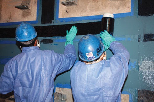
SPS designed the repair to use V-Wrap C-180 18 oz/yd² (580 g/m²) unidirectional fabric from specialty reinforcement systems supplier VSL (Hanover, Md., also part of Structural Group) and made from Toray 700 ksi carbon fiber (Toray Carbon Fibers America, Flower Mound, Texas). According to SPS VP of sales Jay Thomas, “We wanted very high strength so that we could minimize the amount of fiber needed. This was driven by the restoration team’s goal of disturbing the concrete as little as possible.”Before the strips could be applied, significant surface preparation was required. Unlike its smooth exterior (the side against the wooden form), the wall’s interior surface was too rough, a result of pneumatically “shooting” the gunite. Thomas explains, “This surface had to be smoothed — not an easy job on 7,000 psi concrete, which is basically like marble in hardness. It is also important to open up the concrete pores so that the resin absorbs into it, forming a mechanical attachment.”
After the wall surface was smoothed with grinders, a styrene-free, no-VOC/no-HAP vinyl ester resin selected for use with the V-Wrap was thickened with cabosil and applied to the wall as a thixotropic primer to fill imperfections and act as a tack coat for the CFRP strips. Then the wallpaper-like V-Wrap strips were saturated with the same, but unthickened, resin using SPS-built saturating machines that were scaled-down and built from aluminum for easy transport and use at construction sites. Strips 30-ft/9m long and 6- to 8-inches (152-mm to 203-mm) wide were applied both horizontally and vertically to form a grid (see illustration, at right). Strips were allowed to cure to a tack-free state at room temperature for eight hours or were quickly UV-cured, depending upon location and construction schedule.
Bridging load gaps
Although the carbon fiber composites achieved the goal of re-establishing the wall’s tensile capacity, Thomas points out, “The other challenge we faced was how to provide load transfer through the intersecting web walls. The carbon fiber could not be continued through these intersecting walls.” Steel brackets and anchor bolts were used to restore continuity and load transfer through the web wall intersections. Thomas describes the solution: “First a hole was drilled through the bisecting web wall, and then a high-tension bolt was installed into that hole. Next, the steel brackets were attached to the bolt on both sides of the wall and then adhered to the carbon fiber bands.” Thus, the load would be transferred along the wall through the carbon fiber, then into the bracket through the wall via the bolt and finally back out to the carbon fiber via the opposing bracket (as in the diagram at right). Steel brackets also reinforce the connection between the bottom of the ramp wall and the ramp floor slab, and steel braces at the top of the ramp wall help the structure resist wind load yet still allow wall movement.To ensure that the composite repair conformed to ACI-440 guidelines, SPS performed bond tests. Square 1.5-inch (38.1-mm) dollies equipped with a female thread were glued to the composite. A portable pull-off adhesion tester was used to measure the force required to pull the dolly away from its substrate. The tests averaged more than double the ACI-440 required minimum of 200 psi (14 kg/cm²).
In addition, RSA hired an independent inspector who used acoustic tap testing on cured areas to detect any delaminations or air inclusions. Yeadon confirms, “As SPS applied the CF repair, the inspector periodically checked for air voids behind the CFRP strips using tap testing. He did actually find a few, which were immediately repaired.”
A Wright outcome
Under a tight schedule, the project had to be completed between Memorial Day and Labor Day in 2007, the only open window between scheduled art exhibits. According to Hudson, carbon fiber was the key: “I can’t think of any other material that would have conformed to the curvature and satisfied the variety of different installation and molding requirements.”“The carbon fiber system caused the least amount of impact from a preservation standpoint [and] delivered the 100-year service life demanded,” Thomas adds. “We arrived with fabric and buckets of resin instead of a crane and tons of steel. The CFRP system was faster, quicker and more cost-effective.We not only met our deadline but also came in under budget.”


.jpg;maxWidth=300;quality=90;format=webp)


Related Content

The making of carbon fiber
A look at the process by which precursor becomes carbon fiber through a careful (and mostly proprietary) manipulation of temperature and tension.
Read More
The lessons behind OceanGate
Carbon fiber composites faced much criticism in the wake of the OceanGate submersible accident. CW’s publisher Jeff Sloan explains that it’s not that simple.
Read More
One-piece, one-shot, 17-meter wing spar for high-rate aircraft manufacture
GKN Aerospace has spent the last five years developing materials strategies and resin transfer molding (RTM) for an aircraft trailing edge wing spar for the Airbus Wing of Tomorrow program.
Read More
Plant tour: Joby Aviation, Marina, Calif., U.S.
As the advanced air mobility market begins to take shape, market leader Joby Aviation works to industrialize composites manufacturing for its first-generation, composites-intensive, all-electric air taxi.
Read MoreRead Next

CW’s 2024 Top Shops survey offers new approach to benchmarking
Respondents that complete the survey by April 30, 2024, have the chance to be recognized as an honoree.
Read More
Composites end markets: Energy (2024)
Composites are used widely in oil/gas, wind and other renewable energy applications. Despite market challenges, growth potential and innovation for composites continue.
Read More
From the CW Archives: The tale of the thermoplastic cryotank
In 2006, guest columnist Bob Hartunian related the story of his efforts two decades prior, while at McDonnell Douglas, to develop a thermoplastic composite crytank for hydrogen storage. He learned a lot of lessons.
Read More