
Proving performance in EV powertrains
Simulation-driven development replaces aluminum with thermoplastic composites in gearbox housing.

Reducing weight while maintaining performance
ARRK/P+Z Engineering, ARRK Shapers and ARRK LCO Protomoules brought together powertrain, metals and composites expertise to redesign and prototype this EV gearbox housing using continuous carbon fiber-reinforced PA6 organosheet overmolded with short glass fiber-reinforced PA6 molding compound. The simulation-driven approach produced a design that saved weight while maintaining a rigid, efficient and quiet transmission housing.
Source for all images | ARRK Group
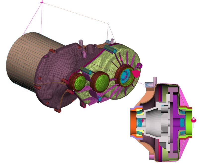
Fig. 1 A Simulation-driven development
ARRK Engineering used multiple simulations to develop this hybrid fiber-reinforced thermoplastic composite gearbox housing including FEM for dimensioning and evaluation of concepts.
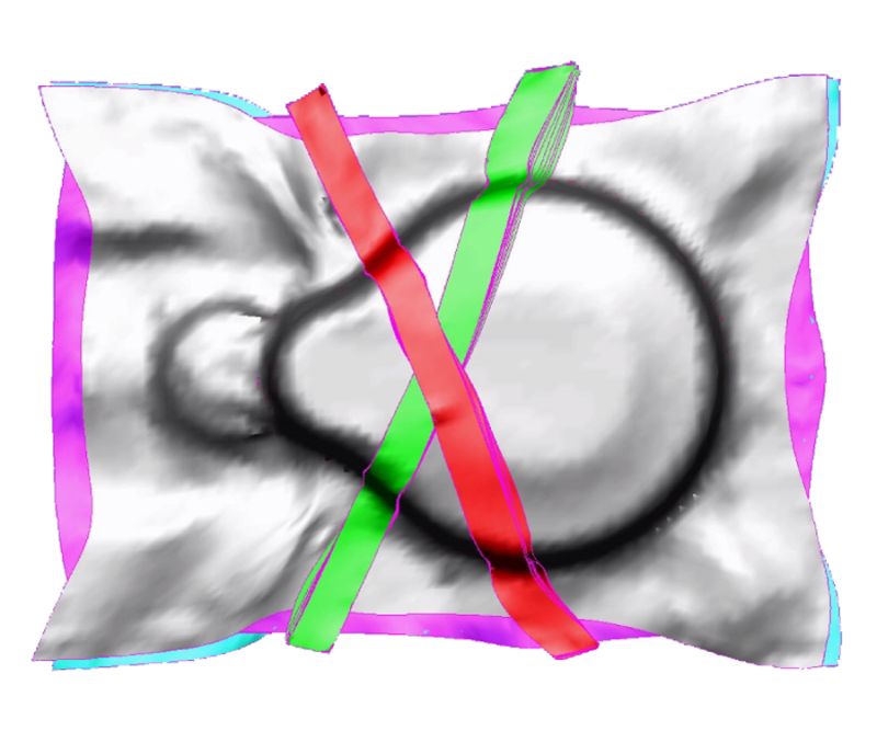
Fig. 1 B Simulation-driven development
ARRK Engineering worked with partner ESI Group to simulate stamping of the organosheet and UD tape preform using PAM-FORM software.
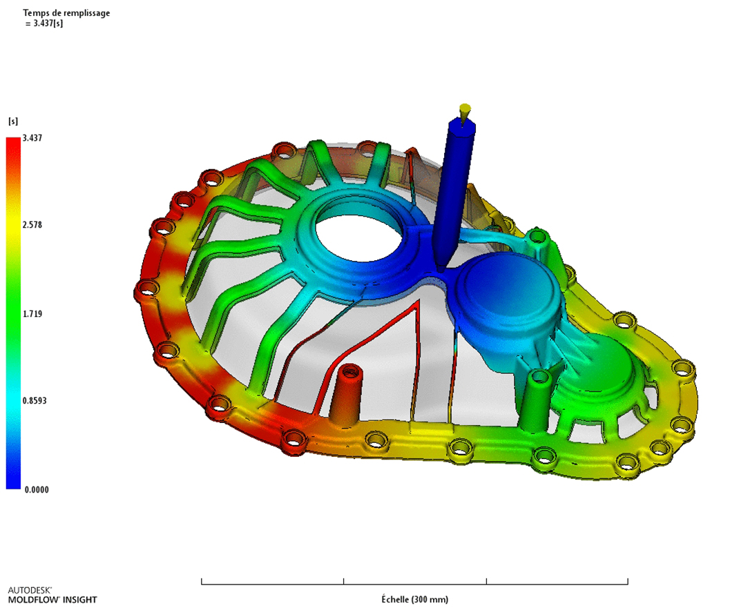
Fig. 1 C Simulation-driven development
Overmolding of the stamped preform was also simulated using MoldFlow and Moldex3D software to virtually prototype the part before investing in tooling.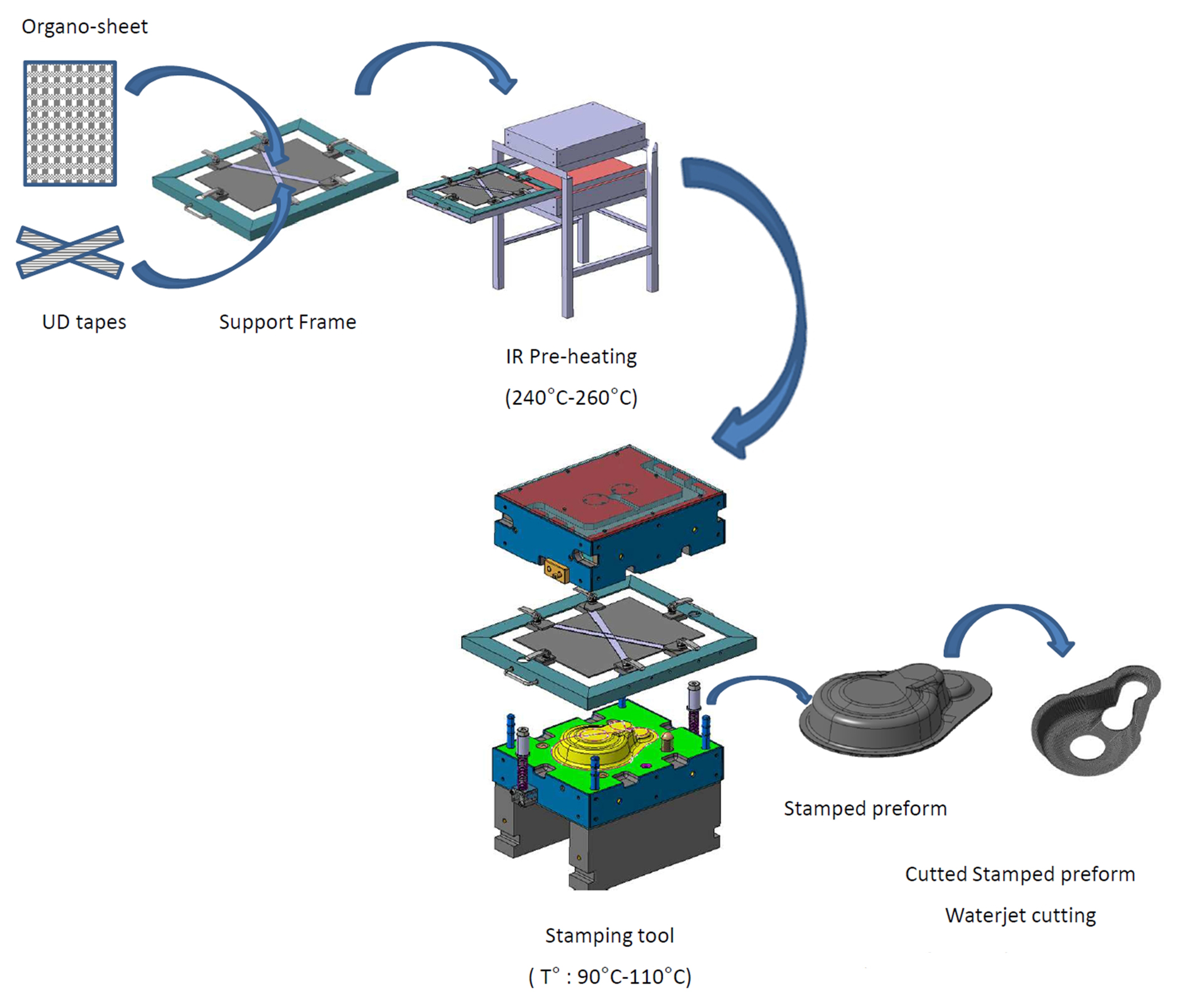
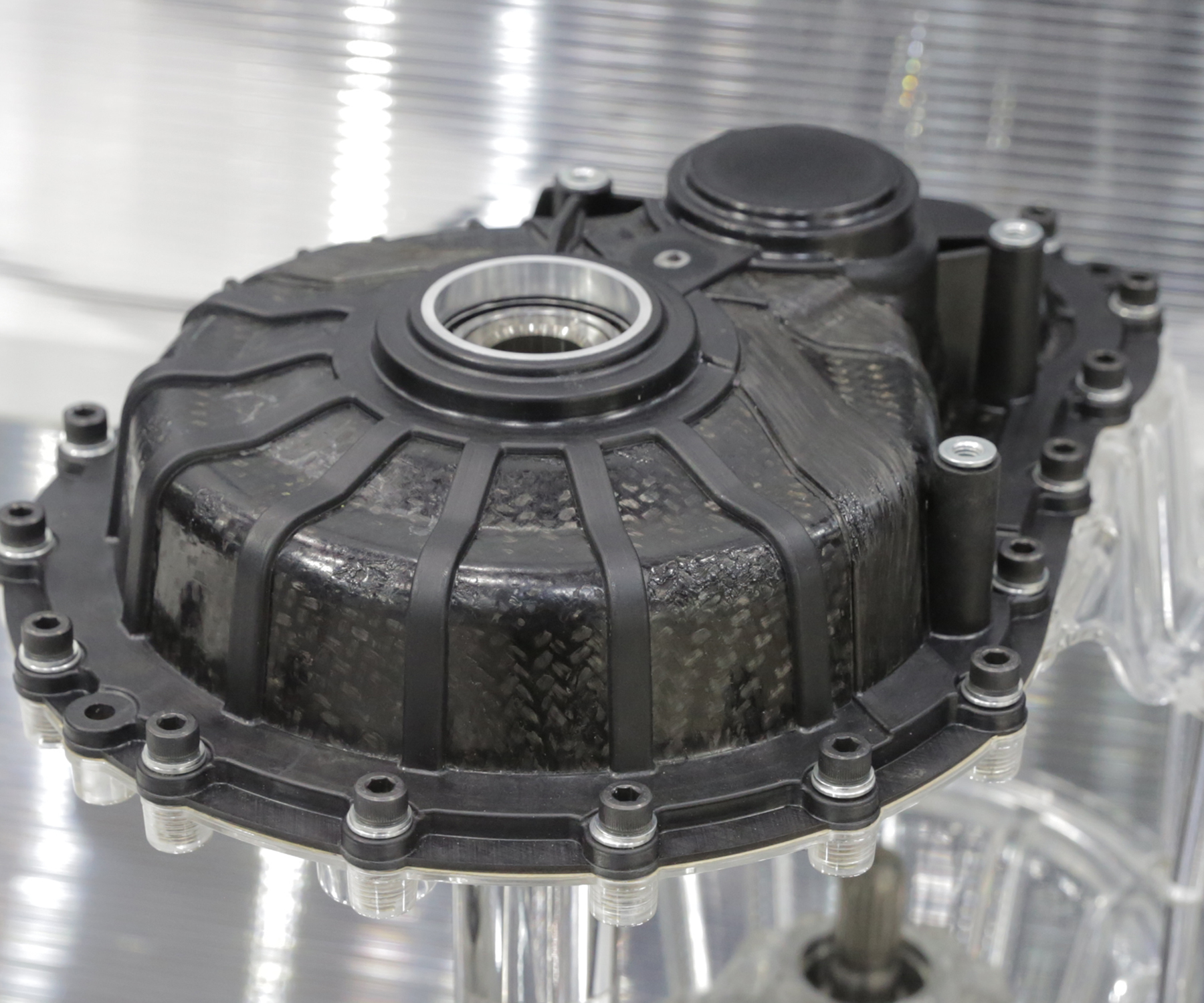
Fig. 2 Finalized process for first prototype
The first half of ARRK Engineering’s redesigned composite gearbox housing was produced using the process steps shown above, followed by overmolding and final milling of part flanges and bearing seats.


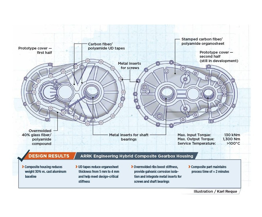
Weight reduction continues to be a goal for electric vehicles (EVs), improving performance and extending range. To that end, designers and manufacturers are exploring the use of composites in battery enclosures, body panels, chassis structures and suspension components. However, one project has set its sights on the powertrain beyond batteries to the gearbox housing, replacing cast aluminum with a hybrid carbon fiber- and glass fiber-reinforced thermoplastic composite to cut weight by 30%.
This project was engineered by multiple companies within the ARRK Group (Osaka, Japan). Founded in 1948, the group comprises 20 companies in 15 countries, with more than 3,500 employees, and provides product development services including design, prototyping, tooling and low-volume production to multiple industries. Since early 2018, ARRK Corp. has been a subsidiary of Mitsui Chemicals Group (Tokyo, Japan), which produces long fiber-reinforced thermoplastic compounds and unidirectional (UD) carbon fiber/polypropylene (CF/PP) tapes. ARRK has established composites as one of its 14 centers of competence, joining the German industry associations Carbon Composites e.V. and MAI Carbon in 2012 and Composites UK in 2015.


For this gearbox housing project, engineering was completed by ARRK/P+Z Engineering GmbH (Munich, Germany) with support from ARRK Shapers’ France (La Séguinière and Aigrefeuille-sur-Maine, France) for the production process as well as stamping and molding tools, while prototyping was led by ARRK LCO Protomoules (Alby sur Chéran, France). “The aim was to demonstrate the light weight and stiffness that fiber-reinforced thermoplastics can provide for electric vehicle engine and transmission components typically cast from aluminum,” explains ARRK Engineering project leader Raik Rademacher.
The gearbox used as the basis for this project is made by Getrag (Untergruppenbach, Germany) for the Smart Fortwo electric city car. Only the housing was redesigned, with all interior parts reused and operating without change. The re-engineering approach employed a variety of simulations — finite element model (FEM), topology optimization and simulation of preform stamping and injection overmolding processes. It also proved out a process for converting a metal design to composite using multiple partners with diverse materials, process and structures expertise.
Defining targets, loads and materials
This EV gearbox housing comprises two halves mechanically fastened around the vehicle’s transmission gears and shafts. The concept phase began by defining design targets. The first step was to reverse-engineer a finite element model by 3D scanning a disassembled Fortwo gearbox, including the internal components, shafts and gears. Maximum input and output torque, the gear ratio and torque on the input and output shafts were derived from manufacturer’s data. An FEM simulation was then used to calculate torque on the gearbox housing for vehicle drive and coast loads, as well as gravity loads up to 60G to simulate crash situations.
The gearbox housing must handle these loads without exceeding allowable deformation; otherwise, there may be significant deflections in the gear shafts, causing inaccurate contact in the gears. “Such contact will damage the gears and, in the worst case, lead to failure,” says Rademacher. “Transmission errors due to inaccurate gear alignment also lead to unwanted acoustic behavior in the gearbox,” he adds. “They call it ‘whining.’ Because EVs are so quiet, it is important that this composite gearbox be really calm and silent.” Thus, stiffness is a critical performance target, and must match or exceed that of the aluminum baseline.
Identified early on as candidate materials for this redesign, woven glass fiber and carbon fiber-reinforced polyamide 6 (PA6) organosheets from TenCate (Nijverdal, The Netherlands) were tested for mechanical properties. Because the glass fiber composite showed only 50% of the stiffness of the carbon fiber organosheet, the latter was selected. “The material is TenCate CETEX TC912 using 12K fiber in a 2-by-2 twill fabric,“ says Rademacher. “We specified a tailored organosheet made using nine plies in a quasi-isotropic stacking sequence (0°/90°/45°/-45°/90°/-45°/45°/90°/0°)”.
Concept and design phases
Five gearbox housing concepts were developed, but only two offered adequate potential for weight and cost savings, along with low cycle time. Feasibility checks revealed that only one concept permitted sufficient stiffness, by using metal bearing seats. “Seats are the direct connection between the bearings for the gearshafts and the gearbox housing,” Rademacher explains. “We looked at simply injection molding these, but instead chose an overmolded aluminum insert to increase the stiffness.” This concept was thus chosen for development.
Topology optimization to minimize strain energy was performed in the subsequent design phase. From this analysis, gearbox housing geometry was refined, including minimum radii for molded curvatures. This geometry was used to build a simulation model for the detailed design. The organosheet laminate was then further optimized, revealing that the +45°/-45° layers should be the thickest. This correlated well with the fact that torsion in the housing is the main source of deformation that must be resisted.
Housing stiffness was still found to be insufficient, thus crossed UD tapes and overmolded ribs were introduced into the housing geometry. For overmolding, the team selected a 40% glass fiber/PA6 (GF/PA6) compound from EMS-Grivory (Domat/Ems, Switzerland).
Detail phase and manufacturing
Functional fixing points and connections for the two gearbox housing halves were detailed in this third phase of the redesign. The halves would be mechanically fastened, so aluminum inserts were added to the design to transmit bearing loads from the fasteners. Other features were then detailed, including the overmolded flange containing these inserts and the ribs and other functional geometry overmolded onto the housing exterior.
A stamping process was selected for preforming the organosheet prior to overmolding. A stamping simulation was completed (Fig. 1) by partner ESI Group (Paris, France) using its PAM-FORM software to anticipate any problems during preforming and to derive a starting cut for the raw organosheet.
“The simulation showed bending deformation due to the high thickness of organosheet and tight radii in the housing geometry, causing wrinkles in the preform,” says Rademacher. “So, we modified the design radii and reduced the organosheet thickness to 4 mm. This was when we showed that thicker 45° plies should be used, but we couldn’t get such an organosheet from a supplier. We decided to keep the quasi-isotropic stack but apply 45° UDs on top to enable the thickness reduction, while maintaining stiffness.”
The team used 12 plies of 25.4-mm-wide and 0.16-mm-thick CETEX TC910 carbon fiber/PA6 tape and reran stamping simulations. These showed that the crossed UD tapes were sliding out of place during stamping. To address this, slots were designed in the stamping tool to lock the UD tapes in position.
The overmolding process was also simulated, performed by Shapers using Autodesk’s (San Rafael, CA, US) MoldFlow software, and also Moldex3D software from CoreTech System Co. Ltd. (Chupei City, Taiwan). One benefit to overmolding was the prevention of galvanic corrosion. The short glass fiber-reinforced molding compound provided isolation between the aluminum fasteners and the carbon fiber in the organosheet. Thus, no additional adhesive, sealant or coating was required.
After completing these simulations, the manufacturing process was finalized as follows (see Fig. 2):
- Organosheet is cut and stacked into quasi-isotropic layup;
- Laminate stack and UD tapes are placed into a frame that maintains tape positioning;
- Infrared heater melts thermoplastic matrix to 240-260°C;
- Frame with preform materials is transferred to stamping press and tool (preheated to 90-110°C);
- Preform is stamped (5-second cycle time);
- Consolidated preform is trimmed to final shape using a waterjet cutting system;
- Shaft bearings and screw inserts are placed into the overmolding tool while trimmed preform is again preheated;
- Preform and inserts are overmolded (2-minute cycle time including manual placement and removal);
- Final part flanges and bearing seats are milled to required tolerances.
Prototype and process success
The first half of the prototype composite gearbox housing was produced and displayed at JEC World 2017. It was then tested to validate the FEM simulations. The prototype showed good mechanical properties, while reducing weight to 4 kg from 5.8 kg for the aluminum baseline, a weight savings of about 30%. The cost of this first half prototype cover is estimated at €50-80, with the organosheet being the most expensive component.
This project also succeeded in prototyping how this collection of companies works together to deliver a composites redesign. “Our background at ARRK Engineering was in simulation for small composite parts but not in using organosheet,” Rademacher recalls. Shapers had extensive experience with injection molding and development of molding tools, but also no organosheet background. The ARRK team working on organosheet simulation were experts in composites simulation, but their previous work had been in aerospace. “We had discussions with the teamevery week,” says Rademacher. “I am from the powertrain department, so more on the metals side, but as the project leader, I had to combine these metals and composites worlds. We metal guys think, ‘Why do it in composites?’ while the composites guys think, ‘this is easy to do in composites.’ We are too skeptical, and they are too optimistic, so it was good to work together. We learned a lot and have developed a design process which is very efficient.” He compares the ARRK process with the more common method of developing one design, using less simulation and then trying to optimize through building iterative prototypes. “We see that it’s more efficient to start with multiple designs and down-select from these using simulation, and then further optimize the design before prototyping. It takes time in the beginning to do this modeling, but less time during prototyping, so it’s less expensive.” Rademacher points out that due to the time and cost of producing new tooling, “It’s always more costly to produce ten prototype parts vs. ten simulation models.”
Challenges and next steps
The team also overcame significant manufacturing challenges. “The UD tapes in combination with the nine-ply organosheet laminate had areas where it was not consolidated,” Rademacher notes. “This was partly due to air between the tapes and the organosheet and also affected their attachment after molding. The other contributor was a non-homogeneous temperature distribution across the organosheet. It looked good in our measurements, but was a little colder at the outer edges, which caused small areas of matrix failures in the outer structure. So, we have learned a lot about both the modelingand actual molding of organosheet parts.”
The next step in the project is to prototype the second half of the gearbox housing and validate the stiffness of the complete assembly. The team is also working to remove the waterjet cutting step so that the preform stack may be immediately overmolded after stamping. “Because we have changed the process, we are still working on the second cover,” says Rademacher. “The biggest challenge for us now is reaching an acceptable price for the client. We are looking at glass fiber and a polyphenylene amide (PPA) matrix, the latter enabling higher performance at high temperatures while further reducing organosheet thickness. We won’t use woven fabric but maybe stacked tapes to help meet the required stiffness.”


.jpg;maxWidth=300;quality=90;format=webp)

Related Content

Recycling end-of-life composite parts: New methods, markets
From infrastructure solutions to consumer products, Polish recycler Anmet and Netherlands-based researchers are developing new methods for repurposing wind turbine blades and other composite parts.
Read More
Price, performance, protection: EV battery enclosures, Part 1
Composite technologies are growing in use as suppliers continue efforts to meet more demanding requirements for EV battery enclosures.
Read More
Cryo-compressed hydrogen, the best solution for storage and refueling stations?
Cryomotive’s CRYOGAS solution claims the highest storage density, lowest refueling cost and widest operating range without H2 losses while using one-fifth the carbon fiber required in compressed gas tanks.
Read More
The making of carbon fiber
A look at the process by which precursor becomes carbon fiber through a careful (and mostly proprietary) manipulation of temperature and tension.
Read MoreRead Next

Composites end markets: Energy (2024)
Composites are used widely in oil/gas, wind and other renewable energy applications. Despite market challenges, growth potential and innovation for composites continue.
Read More
CW’s 2024 Top Shops survey offers new approach to benchmarking
Respondents that complete the survey by April 30, 2024, have the chance to be recognized as an honoree.
Read More
From the CW Archives: The tale of the thermoplastic cryotank
In 2006, guest columnist Bob Hartunian related the story of his efforts two decades prior, while at McDonnell Douglas, to develop a thermoplastic composite crytank for hydrogen storage. He learned a lot of lessons.
Read More