
.png;width=70;height=70;mode=crop;format=webp)


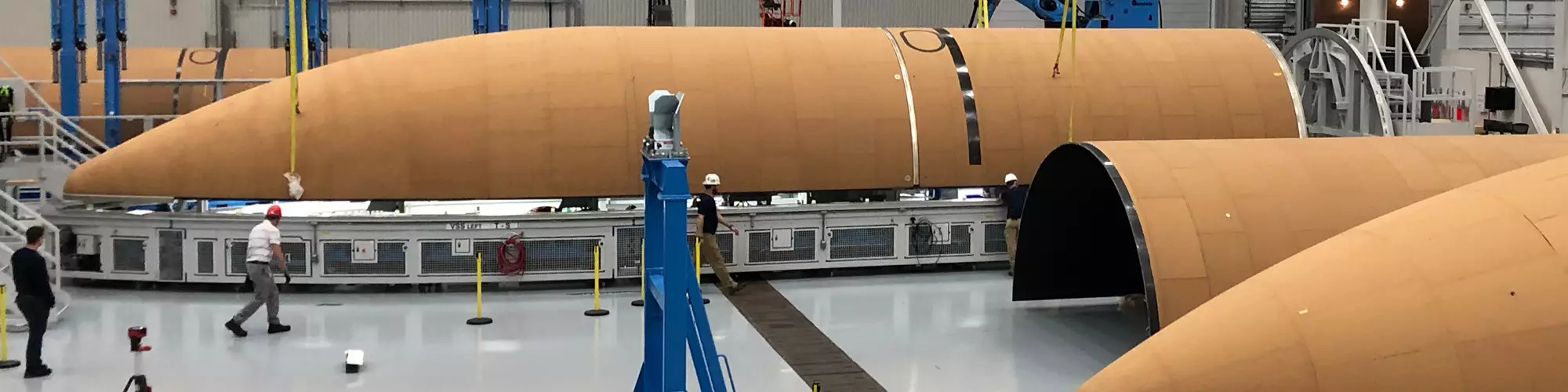
Launcher systems. Composite payload fairings in various stages of completion at RUAG Space’s Decatur, Ala., U.S. facility. CW Photo | Scott Francis
In 2015, United Launch Alliance (ULA, Centennial, Colo., U.S.) announced a strategic partnership with RUAG Space (Zurich, Switzerland; renamed to Beyond Gravity) that would move production of composite structures for the Atlas V rocket to the U.S. The move was part of a transition by ULA from the Delta and Atlas rocket programs toward the next-generation Vulcan family of launchers, which will start with the Vulcan Centaur as early as 2021. The Vulcan program will adapt and evolve technologies of Delta and Atlas, consolidate the expenses of the two lines and allow for ULA to retire the currently used Russian-developed RD-1 engine in favor of the BE-4 engine developed by Blue Origin (Kent, Wash., U.S.). The Vulcan program will serve satellite launches as well as crewed missions. The first planned Vulcan mission is to launch an Astrobotic (Pittsburgh, Pa., U.S.) lunar lander in 2021. A Sierra Nevada Corp. (Sparks, Nev., U.S.) Dreamchaser mission is slated for later that year.
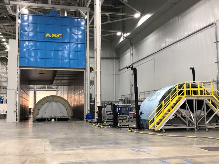
As part of the partnership, RUAG Space set up shop in Decatur, Ala., U.S., in a 130,000-square-foot ULA building that was originally used for the Delta program, and began production in 2017. The company stripped nearly everything out of the facility, polished and leveled the floors and installed all new equipment. Parts of the flooring were taken out to put in reinforcements for the 54-ton payload fairing mold that enables RUAG Space’s out-of-autoclave (OOA) process. Today, the only recognizable remnant of the old Delta building is the repurposed paint booth.


While development and qualification of the Vulcan hardware is underway and is part of the work happening at the Decatur facility, RUAG Space is also working to produce parts for currently scheduled Atlas flights. The Decatur operation delivers carbon fiber composite structures for ULA’s Atlas launchers, including the payload fairing for the Atlas V-500 launcher and the interstage adapter for the Atlas V-400, as well as carbon fiber structures for qualification of the new Vulcan launcher — namely, payload fairings, interstage adapters and heat shields. While the Decatur plant has been up and running for a few years, the first parts produced at the facility that will appear on upcoming missions are just now reaching completion. Until now, RUAG Space parts that appeared on currently used spacecraft came from Switzerland. With Atlas parts scheduled for flights in the coming year and with Vulcan rocket production on the horizon, the Decatur plant is poised for some exciting days ahead. Plant manager Randy Darling gave CW a tour and explained the layout of the facility and function of its equipment.
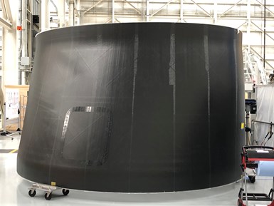
Heat shield. This heat shield demonstrator for the Vulcan program is made using a similar sandwich construction to the payload fairings. CW Photo | Scott Francis
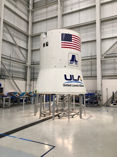
On the plant floor at various stages of completion were an Atlas V payload fairing that will be used on a flight scheduled for October 2020, an Atlas V interstage adapter that will be on a solar orbiter mission scheduled for February 2020, and various parts for qualification for the Vulcan program, including a heat shield demonstrator and a payload fairing demonstrator that will be used for acoustic testing and vibration frequency identification.
RUAG Space’s payload fairings use a sandwich architecture composed of aluminum honeycomb material from Hexcel (Stamford, Conn., U.S.) laid up between an inner and outer face sheet of woven carbon fiber prepreg from Solvay (Alpharetta, Ga., U.S.). A layer of cork applied to the outer face provides thermal protection against the frictional heat generated during launch. Paint on the outside of the payload fairing keeps it from absorbing moisture and reflects the heat of the sun as the rocket sits on the launchpad. The payload fairings comprise two longitudinal halfshells that are mechanically fastened together during launch preparation. Atlas fairings measure 5.4 meters in diameter and are available in three lengths: 20.7 meters, 23.4 meters and 26.5 meters. The components for each fairing half shell are consolidated and oven-cured as one single sandwich structure.
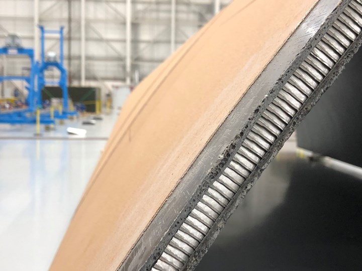
Sandwich construction. Aluminum honeycomb core is sandwiched between an inner and outer skin of carbon fiber prepreg and then covered with a layer of cork to form the payload fairing. CW Photo | Scott Francis
Material preparation and layup
The first stop on CW’s tour is the core expansion table and area for core bending. Here, the aluminum honeycomb core material is cut from compressed blocks, expanded and, using a dedicated tool, is bent into a radius corresponding to the part being fabricated.
Next to the core material preparation area is a CNC cutter supplied by Zünd (Altstätten, Switzerland) for cutting individual pieces of material. The cutter has an interchangeable head and can be used for cutting carbon fiber prepreg, aluminum honeycomb core and cork. The machine also marks each piece with a serial number to indicate location in the layup.
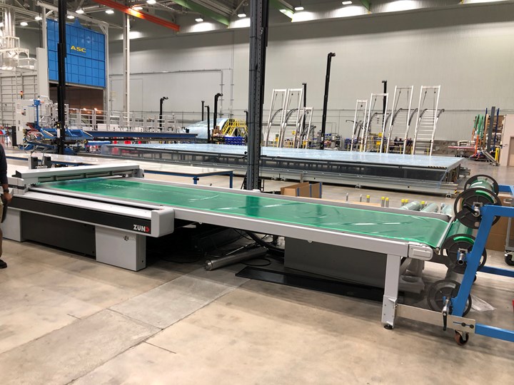
Material prep and layup. A CNC cutter table is used to cut custom shaped pieces and a semi-automated layup table is used to layup the large skins for the cylinder section of the payload fairing. CW Photo | Scott Francis
After it is cut, all material is then prepared for layup to build the composite structures. Because of the payload fairing’s shape — cylindrical with an ogive or cone-shaped portion at the end — it is laid up in two portions simultaneously using two molds to improve efficiency.
Large sections of ply that can exceed 15 meters in length are used for the cylindrical section of the payload fairing and are laid up using an approximately 6-meter by 21-meter CNC-controlled layup table custom-built by Eugen Ostertag Automation (Laichingen, Germany). A semi-automated fabric lay-down machine rides along rails on the edges of the table and rolls out woven prepreg for the inner and outer face sheets. Depending on the design, the table can lay up in straight plies or 45-degree diagonals. Layup on the table is guided by a laser projection system provided by Virtek Vision International (Waterloo, Ontario, Canada). A vacuum-bagged debulk is performed after each ply placement.
“This makes the material adhere to itself and takes the bulk out of it, making it possible to pick it up and drape it over the mold,” says Darling.
As Darling explains, one layer is laid out and debulked, and then the process repeats for subsequent layers until the correct number of plies is reached. Once complete, a dedicated jig is used to lift the inner face sheet and drape it over the cylinder section of the main bonding mold.
At the same time, the layup of the inner face sheet of the ogive section is performed by hand on the main mold. “The ogive is a complex shape and requires a lot of custom pieces,” says Darling. “Laser towers lock into points along the mold and during hand layup of those individual pieces, the lasers project the shape and position where each piece needs to go.”
Once the ogive portion of the inner face sheet is complete and the cylindrical section is in place on the main mold, the aluminum honeycomb core is laid up over the entire inner face sheet. With the honeycomb in place, another debulking step is performed.
“We do several steps of debulking on the mold to help it retain its shape,” says Darling.
As the core material is being placed, layup of the outer face sheet of the cylinder section of the payload fairing is being performed on the layup table and will be draped over the mold as with the inner face sheet. Meanwhile, to save processing time, the outer facing for the ogive is laid up on a secondary mold with another set of lasers projecting the position of the custom pieces. Here, layup of the ogive’s entire outer face sheet and cork layer is done simultaneously. A debulking step is performed, and then a dedicated jig is used to transfer the ogive outer facing to the main mold. Finally, a layer of cork is applied to the outer face sheet of the cylindrical section.
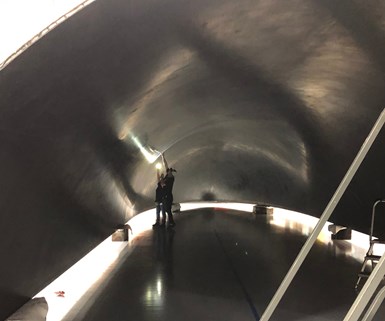
Fairing molds. RUAG Space’s payload main bonding mold (left) is positioned in the large curing oven. A secondary mold (right) is used for the layup of the outer skin of the ogive section of the payload fairing. CW Photo | Scott Francis
Placing the cork is a very manual process, says Darling. To place the material, technicians climb up and down arched, “rainbow” ladders that extend into the mold. Cork is laid by hand sheet by sheet, guided by lasers that project shape and position for each numbered piece from nearby laser towers.
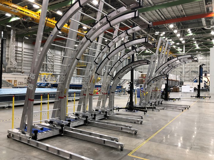
Ladders and lasers. Shown here are ladders used to place material on the bonding mold and the laser towers that project the shape and position for each piece. CW Photo | Scott Francis
According to Darling, having the secondary mold as well as simultaneous processing of the different layups for the cylinder and ogive cuts the overall processing time by at least 60% compared to using a single mold and ensures curing of the sandwich structure before prepreg expiration. With the layup complete, the entire part is ready for vacuum bagging and cure.
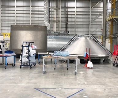
More molds. Bonding molds for the heatshield (left) and payload attachment fitting (PAF). CW Photo | Scott Francis
In addition to the molds for the payload fairing halves, molds for the Vulcan heat shield and payload attachment fitting (PAF) are located nearby. Material layup for these parts is conducted in a similar manner to the payload fairings.
Also nearby is a cork drying oven and an edge cutter for putting chamfers on the cork.
“Coming from the ogive of the rocket there is a chamfer down to the main body,” explains Darling. “The top has thicker cork to protect from the heat of the launch, while the main body has a thinner layer of cork.”
Out-of-autoclave curing
Once layup is complete, the bonding mold with the payload fairing half shell sandwich construction is moved into the large curing oven supplied by ASC Process Systems (Valencia, Calif., U.S.). The oven floor features a center channel with ductwork that redirects air up into the mold. The heat flows out across the face sheet of the mold and comes down the sides. It returns in the ceiling and is recirculated. Thermal mapping and baffles allow technicians to control the thermodynamics of the mold.
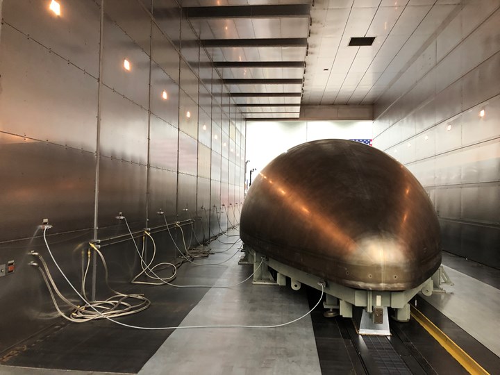
Main bonding mold. RUAG Space’s main bonding mold is shown here inside the curing oven. Thermocouples monitor the temperature of the layup during processing. CW Photo | Scott Francis
During the cure, the oven is monitored for vacuum pressure integrity. Thermocouples monitor the temperature of the face sheet, giving real-time feedback to the oven, which monitors channels against a recipe, allowing operators to make real-time adjustments as needed.
Each air return in the ceiling of the oven represents an independent zone on the mold that the team is able to individually moderate. In addition, multiple parts can be cured simultaneously as long as the recipe is similar, which yields efficiency gains. This also allows RUAG Space to cure test coupons along with the payload fairing. The coupons are subjected to destructive testing including strength, structural, twisting and bending tests, and are cut to check for porosity.
Visual inspection. Manual inspection is conducted prior to ultrasonic NDI. CW Photo | Scott Francis
After cure, the payload fairing half is moved to the inspection station for nondestructive inspection (NDI). First, however, manual inspection is used to check the inside surface finish, looking for voids, porosity and inclusions. An ultrasonic NDI is then conducted to search for voids and foreign object debris (FOD) undetected by the visual inspection. Genesis Systems (Davenport, Iowa, U.S.) supplied the NDI system, which is carried on KUKA (Augsburg, Germany) robots.
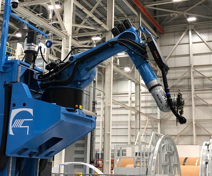
NDI. Ultrasonic NDI is then conducted to search for voids and foreign object debris (FOD). CW Photo | Scott Francis
Postcure
Once the inspection is complete, the payload fairing half moves to a horizontal integration station where a machine executes precision cuts and drills holes, enabling the installation of the payload fairing’s separation systems — a horizontal system that separates the fairing from the launch vehicle and the vertical system that jettisons the payload fairing halves enabling deployment of the payload. A saw runs along tracks down each side of the fairing half, trimming its perimeter to final dimensions. A second cutter goes over the radius of the fairing shell and trims the back.
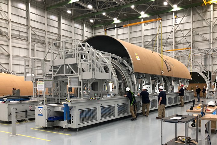
Horizontal integration station. Separation systems are installed and the payload fairing is trimmed using a specialized machine. CW Photo | Scott Francis
“This has to be precise,” says Darling. “We cut and install the separation system on one shell and then we only cut and drill the other shell, and we have to guarantee that two halves will come together. The only way we can do that is with this machine.”
The machine is configurable for different lengths, which makes it possible to work on different models of the payload fairing. Atlas payload fairings are available in 3 aforementioned lengths and Vulcan fairings will be available in 2 lengths (15.5 meters and 21.3 meters). Interstage adapters can be trimmed using the machine as well.
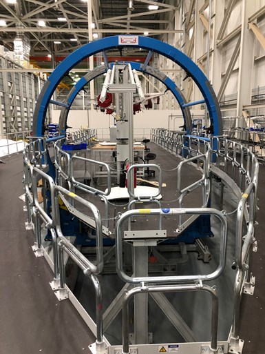
Machining station. A dedicated machine is used to lift and rotate the parts, allowing full access to make cutouts. CW Photo | Scott Francis
From here, the payload fairings move to a machining station where cutouts are made manually using diamond-tipped routers. The payload fairing is mounted on a movable jig that lowers, lifts and rotates the structure nearly 90 degrees in any direction. A surrounding operator platform allows technicians to stand comfortably with full access to perform cutouts. Mechanical templates and jigs are attached to the side of the fairing, and the cutter follows the path to make the necessary cuts by hand.
According to Darling, cutout configurations on the payload fairings change based on individual missions and payloads. Because of the complexity of payload fairing customization, Darling says it’s easier and more efficient for RUAG Space to use hand machining to cut features, such as an access door, rather than develop and program an automated system. “You’d spend all of your time and money programming instead of actually getting work done,” he says.
In the final step, completed fairings are painted with a special electrically conductive paint that dissipates static electricity during the launch.
Vertical integration station. After parts, such as this interstage adapter, are machined and painted, wiring harnesses and mission-specific hardware is added. CW Photo | Scott Francis
Once machined and painted, parts move to the vertical integration station, where technicians integrate environmental controls, ducts, tubing, wiring harnesses and mission-specific hardware. Decals are applied and the parts are ready to go. Learn more about RUAG Space’s OOA process here.
As rocket programs continue to evolve, so does RUAG Space’s approach to making its composite launcher parts. For example, the company is beginning to work with hot bonding for some of joints on Vulcan structures, rather than using a metallic joint with fasteners, contributing to weight savings and cutting down assembly time. RUAG Space is also looking ahead to work on Dynetics’ (Huntsville, Ala., U.S.) Universal Stage Adapter (USA) that will join the upper stage of NASA’s super heavy-lift Space Launch System (SLS) to the Orion crew module, an architecture that will be used for Artemis program missions to the moon. RUAG Space will manufacture the adapter’s 8.4-meter-diameter shells — much larger than the 5.4-meter-diameter Atlas payload fairing shells the company is currently producing, and made in four sections that will be hot bonded together.
With eight Atlas V flights coming this year, and the first launches of the Vulcan Centaur and the SLS planned for 2021, RUAG Space Decatur is in for some busy and exciting days ahead, indeed.


Related Content

EUVAM project investigates energy-efficient UV process for composites curing
University of Stuttgart researchers intend to develop flexible, highly productive and digitally controllable manufacturing approach for small urban vehicle production.
Read More
Addyx carbon exoskeleton technology enables molded ribs inside hollow composite structures
Using a water-soluble mandrel, carbon exoskeleton opens paradigm for topology-optimized composites, cutting weight, manufacturing time and scrap rate.
Read More
GMI Aero extends Anita EZ hot bonder thermocouple capabilities
Thirty-six thermocouples (T/Cs) are now available for flexible temperature monitoring/control during composite curing.
Read More
Real-time assessment of thermoset composites curing
The combination of material state management (MSM) software and an encapsulated sample rheometer (ESR) enables real-time cure recipe management or cure model development inside the autoclave.
Read MoreRead Next

Composites end markets: Energy (2024)
Composites are used widely in oil/gas, wind and other renewable energy applications. Despite market challenges, growth potential and innovation for composites continue.
Read More
From the CW Archives: The tale of the thermoplastic cryotank
In 2006, guest columnist Bob Hartunian related the story of his efforts two decades prior, while at McDonnell Douglas, to develop a thermoplastic composite crytank for hydrogen storage. He learned a lot of lessons.
Read More
CW’s 2024 Top Shops survey offers new approach to benchmarking
Respondents that complete the survey by April 30, 2024, have the chance to be recognized as an honoree.
Read More