
Overmolded hybrid parts open new composites markets
A process that combines continuous carbon fiber-reinforced PAEK with chopped fiber/PEEK overmolding is making inroads in the aerospace market. Parts that previously could not be produced cost-effectively from composites can now be made at less cost than their metal counterparts.


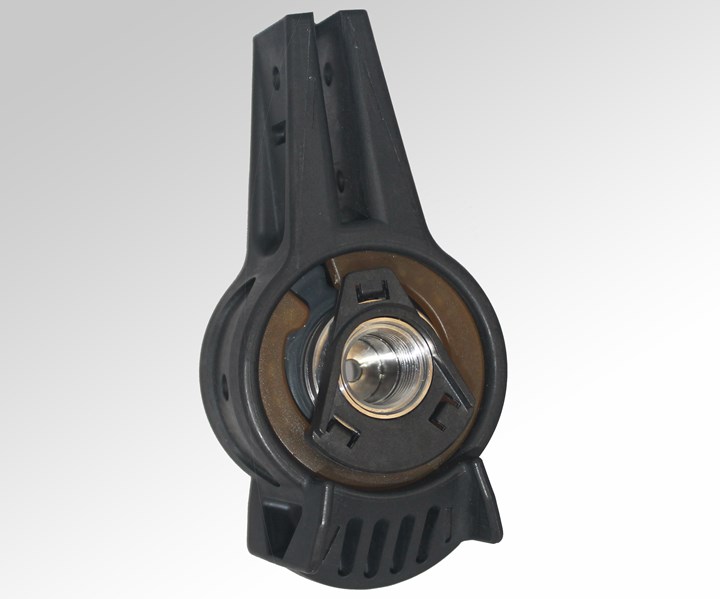
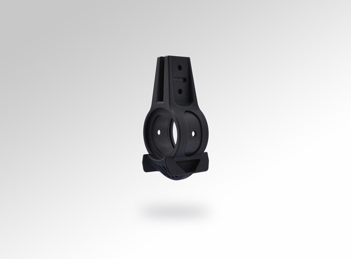
Complexity and strength. Components like the B bracket for aircraft storage bins exhibit both high complexity and a requirement for high strength — a combination for which the hybrid overmolding technique is especially suited. Source, all images | TxV Aero Composites
Often in the aerospace market, an OEM is willing to pay more for a composite component, knowing that the investment will return dividends in fuel savings due to the component’s light weight, a longer life due to less wear and tear, or other reductions in operational and maintenance costs. This “product lifecycle” view has opened many markets and applications to composites. More unusual is a composite component for which the acquisition cost itself is less than that of the metal version. But this is changing. Some new automated composites fabrication processes are starting to tip the scale in favor of composites, and among these is a hybrid overmolding process developed by TxV Aero Composites (Bristol, R.I., U.S.).
A joint venture of Tri-Mack Plastics Manufacturing (Bristol, R.I., U.S.) and Victrex (Thornton Cleveleys, U.K.), TxV has advanced its hybrid overmolding technique to the point of commercial production status. The company has partnered with SFS intec Aircraft Components (Althengstett, Germany) to redesign and commercially produce an aircraft storage bin bracket previously made from aerospace-grade aluminum. A success story of its own, the bracket also demonstrates the potential of hybrid overmolding and VICTREX AE 250 unidirectional carbon fiber/polyaryletherketone (PAEK) tape for valuable weight and cost savings in numerous aerospace applications — advantages achieved by replacing a subtractive metal machining process with a composites process in which material is added, not subtracted.


From subtraction to addition
Machinists and machine shops that produce metal components on CNC machines have nicknamed themselves “chipmakers,” for the obvious reason that their processes cut away unneeded material from metal blanks to make components, creating scrap metal chips. These chips represent a costly aspect of metal machining, whether they are disposed, sent to a recycler, or reprocessed in-house. In the case of SFS intec’s overhead storage bin bracket, 60 to 70% of the aluminum becomes scrap during the several milling steps required to machine it.
This high scrap rate renders the raw material cost for a net-shape or near-net-shape composite version of the bracket potentially lower than the metal material cost. “We can compete against less expensive (per pound) aluminum because of the chips; if the buy-to-fly ratio is 8:1, most of the aluminum purchased becomes scrap,” notes Jonathan Sourkes, TxV senior accounts manager. “Another factor is the time each component spends being milled. We can make [composite] parts in minutes, not hours.”
Beyond raw material costs, composite versions of components like the bracket — featuring a complex geometry and requiring high load-bearing performance — have not been economically feasible using historically available manufacturing options. On the one hand, if the components were made with low-cost, chopped fiber reinforcement in a high-speed, low-touch process like injection molding, the component would not achieve sufficient load-bearing performance. On the other hand, if it were made with higher load-bearing, continuous fiber reinforcement via a low-speed, high-touch process, typically involving some manual layup, production would be too slow and/or impose manufacturing costs that would make the end product too expensive.
Because of these roadblocks to new composites applications of this type, the composites industry as a whole has devoted significant resources to developing automated processes that can produce such components at suitably high production rates and with sufficient load-bearing capability to meet aerospace customer needs and specifications. With an eye toward commercial production of such composite components, TxV came into being in 2017 specifically to accelerate the commercial adoption of innovative manufacturing processes for polyketone-based composite applications throughout the aerospace industry.
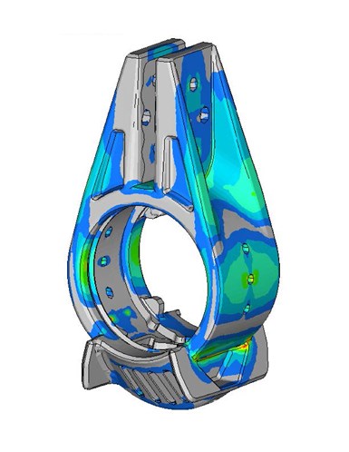
Virtual prototyping. Using proprietary data developed to characterize the relationship between the laminate and overmold, TxV iterated the layups and ply orientations without having to manufacture and test a physical prototype. Iterations continue until the visible stresses, as depicted here, are within the range of load cases provided.
TxV’s overmolded hybrid solution incorporates two key advancements to the state of the art in composite component fabrication. First, it automates the production of those parts of the component that require the strength or stiffness of continuous fiber reinforcement. Second, it leverages the speed of injection molding to complete the component’s complex geometries. More specifically, it produces a tailored laminate to handle loads, which is then overmolded to functionalize and create final part geometries. The hybrid technique, according to Sascha Costabel, head of innovation at SFS intec Aircraft Components, “is a good option for components that must withstand high levels of mechanical stress and geometries that require multiple processing steps where conventional machining is used.”
Partnering with SFS intec has been a great choice, Sourkes says. “As a global leader in system attachments, SFS is always doing something really interesting. They are very innovative and willing to invest in new technologies,” he notes. SFS intec also has a strong relationship with its aircraft customers, he adds, and they possess the capability to perform qualification processes — key to aerospace industry adoption of a redesigned component.
The aircraft storage bin bracket, specifically referred to as a “B bracket,” was chosen as the first attachment component for composites redesign because it is representative of components that are challenging to design and produce. Following collaborative engineering, part conceptualization and design, and modeling of performance via an Altair (Troy, Mich., U.S.) finite element analysis (FEA) tool, the project team iterated from the first article to validate, test and prove out the model. Design for manufacture was central to the development of the composite bracket, which leverages the manufacturing advantages of automated tape laying for the continuous fiber-reinforced elements and high-speed injection molding for the chopped fiber-reinforced elements.
Building B brackets
One key aspect of the hybrid overmolding process is the use of distinct polymers of the same class. PAEK serves as the matrix resin for the continuous fiber composite portions of the bracket, while polyetheretherketone (PEEK) is used in the overmolded areas. VICTREX PAEK and PEEK boast superior fatigue, chemical and corrosion resistance; excellent smoke, flame and toxicity resistance; rapid formability; and weldability. VICTREX AE 250, a lower-melting PAEK (LM PAEK), offers a melt temperature 40 degrees C lower than PEEK’s. “When molten PEEK flows over the surface of the LM PAEK composite, the lower melting temperature allows for a strong attachment,” Sourkes explains.
Specific raw materials for the B bracket are VICTREX AE 250 unidirectional carbon fiber-reinforced PAEK tape (58% carbon fiber) in widths of two inches; and short carbon fiber-filled VICTREX PEEK 150CA30 (30% carbon fiber). These materials feed the hybrid overmolding production work cells, which create the brackets through the following multi-step process.
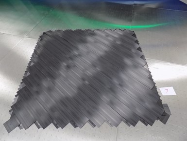
Step 1. A Dieffenbacher Fiberforge 2000 automated tape laying system produces tailored laminate blanks.
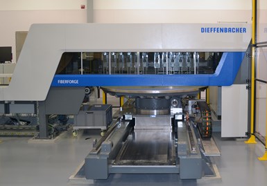
First, the carbon fiber/PAEK tapes are laid down in a tailored blank using a Dieffenbacher (Eppingen, Germany) Fiberforge 2000 tape laying system. “This machine is currently one of the fastest tape-laying systems in the world,” Sourkes attests. It is outfitted with robots to load and reload tape spools, so that it can run uninterrupted, minimizing manual touch time. Layup is designed so that gaps between tapes are minimized. Each ply of the B bracket tailored blank is inspected before the next ply is laid down. The process is performed in an environmentally controlled area to minimize the potential for foreign objects and debris (FOD).
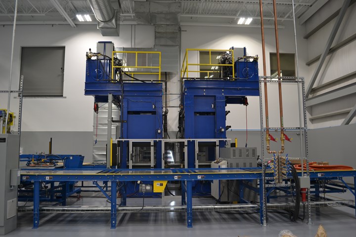
The tailored blanks are then consolidated in an automated bespoke cell that requires minimal manual handling to load and unload the laminates. In the cell, matched heated platens press-consolidate a panel, eliminating voids. Matched cold platens then cool the panel. The two sets of platens, kept at temperature, are much more efficient than a static press with one set of platens. “The result is a drastically reduced cycle time measured in minutes versus hours,” Sourkes says.
Step 2. Tailored blanks are consolidated in an automated bespoke consolidation cell, which features two sets of platens that are kept at temperature (one hot, one cold) to speed this step.
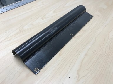
The consolidated laminate preforms are then further processed in a proprietary work cell to form the primary shape of the bracket (Step 3). The final carbon fiber/PAEK inserts are then cut from the formed blanks using a Flow International (Kent, Wash., U.S.) waterjet cutter (Step 4)
Step 3. A proprietary work cell forms the primary shape of the bracket.
In determining the size of the tailored blank, Sourkes points out that a tradeoff must be deliberated for each project. “We can size the laminate so that we can zip out three or four rectangles from a single square blank. By laying up as large a blank as you can, then cutting it into preforms, you maximize the buy-to-fly ratio; but cutting the preforms means more time for waterjet cutting operations.” In the B bracket project, each consolidated laminate is cut into multiple preforms
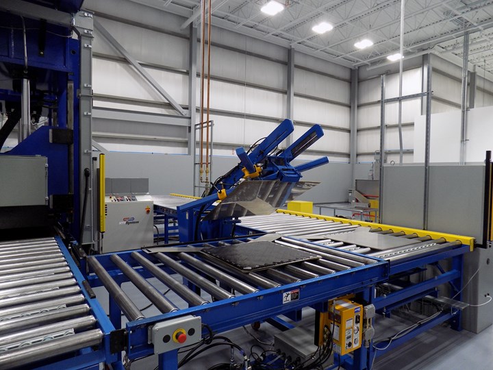
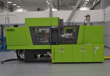
Next is the overmolding step, which is performed with an Engel (Schwertberg, Austria) high-temperature injection molding machine (Step 5). The inserts are placed in an injection molding cavity that is then filled with molten PEEK. The inserts are placed in an injection molding cavity that is filled with molten PEEK, which melts the top layer of the VICTREX AE 250 laminates to create a strong melt-bonded component.
When required, a component is finished via machining to net shape. “While it is our aim to mold near-net parts,” Sourkes admits, “oftentimes some minimal level of machining is required after the fact to clean up process geometry.” Machining may be performed with a waterjet or CNC machining.
Groundbreaking results

Step 4. A Flow International waterjet cutter cuts the carbon fiber/PAEK inserts from the formed blanks. Two of these inserts are used in each bracket.
In manufacturing the SFS intec bracket, the TxV hybrid overmolding process achieves cycle times of three minutes, and a buy-to-fly ratio of 1.06:1. “It is the efficient use of materials and rapid manufacturing process that allows us to produce value-added thermoplastic composite parts, and that makes possible the system cost reductions over the incumbent metal designs,” Sourkes emphasizes. “Effectively we are replacing a lower-cost raw material with a high buy-to-fly ratio and significant processing time with a highly engineered material solution.” The result is weight savings in the 30 to 40% range and cost savings in the 20 to 30% range in a like replacement, that is, a replacement part that follows the same geometric and operational specifications as the existing component. “Weight savings in particular can be as great as 60% when we are afforded the opportunity to completely redesign a part system,” he notes.
Step 5. An Engel injection molding machine optimized for PEEK hybrid overmolding completes the composite part by overmolding the inserts.
The carbon fiber/PAEK/PEEK bracket has also consolidated part count: TxV and SFS agreed to injection overmold a spreader nose onto the bottom of the part in the same operation used to functionalize and add other features. Previously, the spreader nose was made from PEEK and then held in place by two rivets. Thus the consolidation results both in a reduced part count and in the elimination of an assembly step.
Expertise from the two companies that launched TxV undoubtedly has enabled the success of hybrid overmolding. Sourkes explains that, after developing the PAEK material and processing technology, Victrex first explored opportunities with existing business partners. “However, companies with injection molding expertise didn’t have the expertise to work with continuous fiber-reinforced composites, and vice versa.” Victrex and Tri-Mack partnered for several years before forming TxV in 2017 and building the venture’s purpose-built polyketone composite center of excellence, which is highly automated and designed for high-rate serial production.
Asked to compare the TxV process and results with a conventional manufacturing approach, Sourkes notes that the B bracket is not amenable to standard composites manufacturing approaches. “This would be very challenging without machining the bracket from a composite billet — which would be cost-prohibitive,” he says.
Step 6. The final B bracket is produced with a cycle time of three minutes, a buy-to-fly ratio of 1.06:1, and weight savings of 30 to 40%.
Qualify then fly
Taking advantage of SFS intec’s ability to run qualification, the two companies have proceeded with certification through “point design,” which means that only this particular part geometry gains flight approval. Parts were produced and subject to the tests laid out in the qualification document. “Given the part is an overhead bin bracket, the operational loads are fairly easily achieved,” Sourkes notes. “However, the performance requirements go beyond those typical loads and must cover some extreme takeoff and landing maneuvers.” As CW goes to press, the qualification package has been submitted and is awaiting final signoff from the specification custodian. TxV and SFS intec expect the part to be flying early in 2020.
Once the B bracket is qualified, TxV will scale to production volumes. While the company is using its existing hybrid overmolding line to produce these brackets, Sourkes emphasizes that the company has a dual mandate — both to make parts with the technology and to support industry manufacturers interested in adopting the technology themselves. In other words, composites manufacturers may adopt this manufacturing technique in their own facilities.
Composite brackets like the SFS intec product have the potential to take over a fairly large market for these kinds of components. Commercial aircraft use thousands of brackets and system attachments, accounting for significant cost and weight contributions to the overall aircraft. “We are convinced that thermoplastic composite components will play an increasingly larger role in the manufacture of aircraft,” Costabel anticipates.


.jpg;maxWidth=300;quality=90;format=webp)
Related Content

Plant tour: Joby Aviation, Marina, Calif., U.S.
As the advanced air mobility market begins to take shape, market leader Joby Aviation works to industrialize composites manufacturing for its first-generation, composites-intensive, all-electric air taxi.
Read More
Materials & Processes: Fibers for composites
The structural properties of composite materials are derived primarily from the fiber reinforcement. Fiber types, their manufacture, their uses and the end-market applications in which they find most use are described.
Read More
PEEK vs. PEKK vs. PAEK and continuous compression molding
Suppliers of thermoplastics and carbon fiber chime in regarding PEEK vs. PEKK, and now PAEK, as well as in-situ consolidation — the supply chain for thermoplastic tape composites continues to evolve.
Read More
Novel dry tape for liquid molded composites
MTorres seeks to enable next-gen aircraft and open new markets for composites with low-cost, high-permeability tapes and versatile, high-speed production lines.
Read MoreRead Next

From the CW Archives: The tale of the thermoplastic cryotank
In 2006, guest columnist Bob Hartunian related the story of his efforts two decades prior, while at McDonnell Douglas, to develop a thermoplastic composite crytank for hydrogen storage. He learned a lot of lessons.
Read More
Composites end markets: Energy (2024)
Composites are used widely in oil/gas, wind and other renewable energy applications. Despite market challenges, growth potential and innovation for composites continue.
Read More
CW’s 2024 Top Shops survey offers new approach to benchmarking
Respondents that complete the survey by April 30, 2024, have the chance to be recognized as an honoree.
Read More