


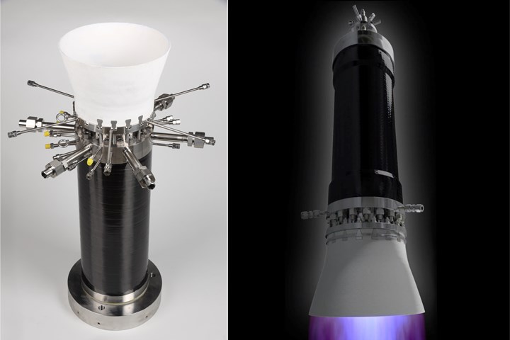
Black Engine is a new thrust chamber design using CFRP, GFRP and CMC composites in a methane-burning, 60-kilonewton propulsion system aimed at the myriad small launch vehicles being developed to send satellites and other payloads into orbit as part of the booming New Space industry. Photo Credit: DLR Institute of Structures and Design
New Space is the economy and ecosystem that is commercializing travel and operations in space. As explained in a workshop by Gary Martin, director of partnerships at NASA Ames (Mountain View, Calif., U.S.), “We are at the cusp of a revolution — new industries are being born that use space in non-traditional ways, with increased competition and new capabilities that will change the marketplace forever.” This fast-forward reinvention of the space industry and its supply chains spans a wide range of activities, such as low and high Earth orbit (LEO, HEO) operations involving satellites and space stations, as well as asteroid mining and zero-gravity manufacturing in deep space. One common thread is the need for more efficient and lower cost reusable launch vehicles.
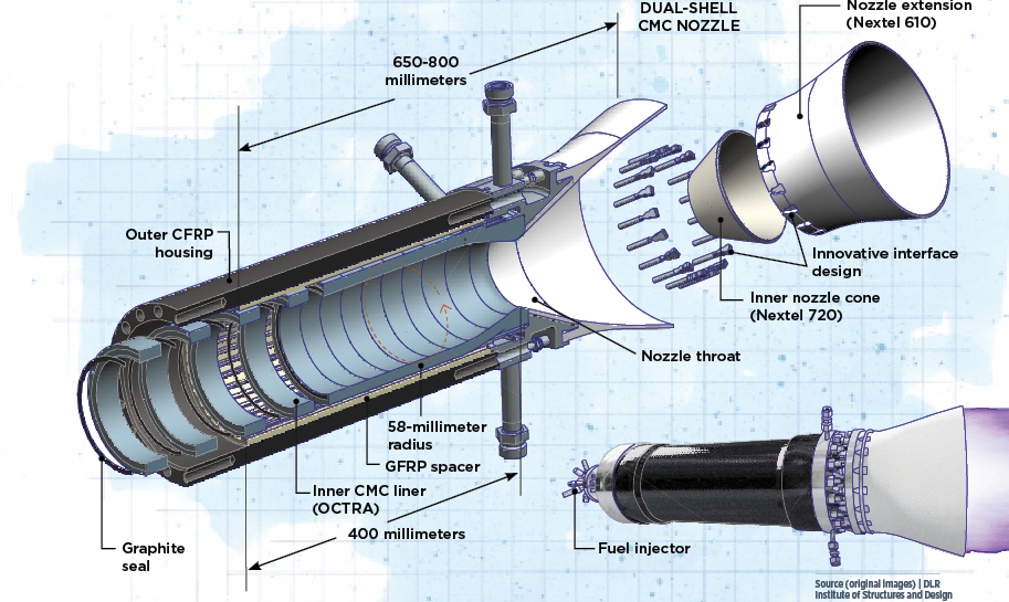
The power to launch a vehicle into space forms in the thrust chamber, comprising a fuel injection system, a combustion chamber for burning the propellants and an expansion nozzle for expelling the resulting gases at high velocity to produce thrust. Most international producers of launcher propulsion systems typically use metal thrust chambers. The German Aerospace Center (DLR) Institute of Structures and Design in Stuttgart, however, has developed a novel design that uses carbon and glass fiber-reinforced polymer (CFRP, GFRP) composites as well as a new type of ceramic matrix composite (CMC). This thrust chamber has a total length of 650-800 millimeters, depending on launch vehicle configuration, and comprises a metallic fuel injector head bolted to a CFRP outer housing. Within this housing, the CMC combustion chamber stretches roughly 400 millimeters with an inner radius of 58 millimeters. A GFRP spacer provides the interface to the outer housing, while a dual-shell CMC nozzle forms the opposite end from the injector.


This multi-material design enables transpiration cooling, which in turn provides a significant reduction in the combustion chamber pressure loss that is typical with legacy metal designs using regenerative cooling. Additionally, the novel use of composites offers the potential to reduce structural weight, perhaps as much as 25%, and increase engine efficiency, with a target of >5%. These materials also enable a modular design that decouples thermal and structural loads and offers the potential for increased reliability, reduced cost and a path forward for further novel optimizations. DLR is in the process of demonstrating this “world-first” technology to a technology readiness level (TRL) of 5 via ground tests of a 60-kilonewton thrust chamber fueled by liquid methane (LCH4) and liquid oxygen (LOX).
Black Engine for New Space
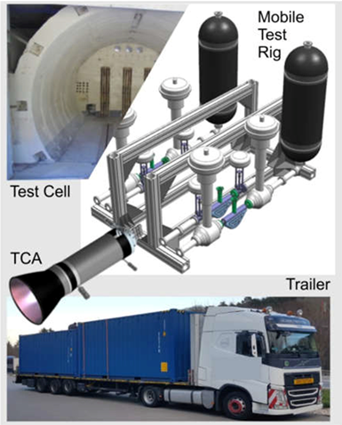
Fig. 1. Mobile test rig
The thrust chamber being developed in the Black Engine project will be ground tested in the mobile test bench being developed by Black Engine Aerospace (BEA). Photo Credit: DLR, BEA
“There are actually three separate entities that are called Black Engine,” explains DLR researcher Markus Selzer. “First, there is the technology, which is for a transpiration-cooled CMC engine thrust chamber. Second, is the Black Engine project, ongoing at DLR since March 2019, to demonstrate this technology in a methane-burning, 60-kilonewton format. And third, we are working together with a spin-off company founded by one of our team members that is also called Black Engine Aerospace [BEA, Heilbronn, Germany]. This new company will bring the Black Engine technology to market. As part of this commercialization, the company is also developing a new mobile test bench [Fig. 1] that can be rapidly transported to test these new rocket engines at customer sites around the world.”
The history of the Black Engine technology reaches back to 2000, says Selzer, with DLR’s first research into transpiration cooling — a rarely used but very efficient cooling method (see below) — and CMC materials in combustion chambers.1 Note, though modern rocket engines don’t normally use transpiration cooling, they all use fuel that also functions as a coolant. In 2010, DLR successfully tested a CMC thrust chamber system fueled by cryogenic liquid hydrogen (LH2) and oxygen at the European Research and Technology Test Facility P8 (DLR Lampoldshausen).2 “We are now further developing that proven technology to use methane and also scale it up to 60 kilonewtons,” he adds.
Why LCH4 as fuel and 60 kilonewtons of thrust? The two researchers first explain the latter. “So, that’s 6 tons of thrust,” says Selzer’s teammate, Helge Seiler, “which is in the range of what is used to power the second stage for a launch vehicle.” In addition to using the engine in a second or third stage, says Selzer, “you would also cluster nine of them in the first stage, for example, to bring 400 kilograms of payload to the ISS [International Space Station]. This aims at the New Space market, where all of these companies are developing small rockets to send satellites and other payloads into various orbits.”
This clustering of small engines sounds very similar to the SpaceX approach with its Merlin engines. “Yes, but the Merlin motors are 15 times more powerful than ours,” notes Seiler. “However,” says Selzer, “there are hundreds of companies in the world that are developing small rockets, and they will eventually need smaller engines like what we are developing. And a lot of these small engines are using methane as fuel. This is because, when looking at the performance of the whole launcher system, methane kind of hits a ‘sweet spot’ of performance, reliability and storability.”
For example, the cryogenic temperature required for LCH4 is 110 K/-162°C, which is the same as for LOX, Seiler explains. “So, the tanks can share the same bottom in the launch vehicle. Even though LH2 is a better cooling fluid, it requires 20 K/-253°C, so that the LOX and LH2 tanks cannot share the same bottom. Also, if you want to fly to the moon or Mars, it’s easier to both store and produce methane.”
Illustrated by Susan Kraus.
Modular, lightweight, decoupled design
As shown above, the Black Engine thrust chamber comprises an outer CFRP housing and inner CMC liner, with a GFRP spacer in between; the left and right ends of the chamber are, respectively, the fuel injector and CMC rocket nozzle. The CFRP housing is made using standard materials, says Selzer. “In the past, we made it ourselves using a vacuum infusion process, but we have now transitioned to a commercial producer of CFRP tubes, Carbon Express [Schwarzach, Germany], using Hexion [Columbus, Ohio, U.S.] 828 epoxy resin and Toray [Tokyo, Japan] 12K fibers.”
“The GFRP spacer is a filament-wound tube with longitudinal stringers or longerons,” says Seiler, “which also provide channels for the fuel coolant. The spacer helps to evenly distribute the methane fuel around the CMC liner and keeps the liner from moving within the CFRP housing.” It also provides guidance for the CMC segments during assembly. “It’s an important part,” adds Selzer, “but it’s not something that takes a lot of load.” To date, the spacers are made in-house by DLR technicians using Hexion RIM 935 epoxy and a mix of P185-EC14-2400 glass fiber roving from Saint-Gobain Vetrotex (Chambéry, France) and Interglas 92125 twill fabric from Porcher Interglas Technologies (Erbach, Germany). That too will be transferred to a commercial producer in the future.
The CMC inner liner is made from stacked rings cut from flat CMC plates. “We put that stack into the outer CFRP tube equipped with the GFRP spacer and then compress the rings and hold everything together using the bolts in the CFRP housing,” says Selzer. “From a manufacturing standpoint, it’s a very easy process. The plates aren’t attached to each other, just compressed using small dowel pins for alignment.”
“It's like the CMC rings are swimming inside the CFRP housing,” notes Seiler. “One advantage of this design is that it decouples the thermal loads, which are carried by the CMC rings, from the pressure loads, which are carried by the CFRP housing. The pressure loads are coming from the nozzle, and also from the combustion and expansion of the hot gas in the combustion chamber.”
He explains that if the chamber was a monocoque, or monolithic shell, then it would have to carry pressure and temperature loads. “Uncoupling these makes the combustion chamber design more reliable,” he points out. “We project that the chamber will last much longer than conventional metal chambers, which typically fail due to thermal loads. These thermal loads are caused by the large temperature differences in the system, ranging from cryogenic temperatures with oxidizer and fuel to the high temperature during combustion. The thermal expansion during a run leads to damage. You can use such engines five to 10 times, but then you have to check for cracks. We expect to avoid this in our chamber.”
“This is one advantage to using a CMC inner liner,” says Selzer, “which has a very low CTE [coefficient of thermal expansion]. So, even if the thrust chamber is cycled from low to high temperatures many times as it is reused, it shouldn't matter. And the structural loads are decoupled anyway.” Another benefit of this approach is if damage occurs during production and reuse, “we just replace that one ring,” says Seiler. “This isn’t possible with one-shot, 3D-printed engines or cylinders.”
New CMC for transpiration cooling
Until late last century, regenerative cooling was standard for almost all rocket thrust chambers. This method relies on convection between the cryogenic fuel, used as coolant, and the hot structure of the thrust chamber, but requires thin walls, which are prone to cracking, and small cooling channels that result in a high pressure loss (roughly 20% of the combustion pressure) in the cryo-fuel coolant flow. These drawbacks degrade the chamber’s ability to withstand the higher temperatures required for increased performance. Film cooling, favored in most rockets today, can reduce thermal and structural loads, but requires large blowing ratios of coolant to overall fuel flow, significantly reducing rocket motor efficiency. Transpiration cooling offers a higher cooling efficiency versus regenerative and film cooling by passing the cryo-fuel coolant through the chamber structure, which is porous. Though its efficiency has been known since the 1950s, suitable porous structural materials have, until now, not been readily available.
“We are using a new type of CMC,” says Selzer. Developed by DLR and called OCTRA, the CMC uses carbon fiber reinforcement in a carbon-silicon carbide matrix (C/C-SiC).3 “The technology is based on materials that have been used by our department for decades,” he explains. “When used in reentry and heat shields, the materials are usually dense and not porous. With OCTRA, we are replacing some of the carbon fibers with aramid fibers, which get destroyed during pyrolysis, so that we end up with a CMC that is porous and thus permeable, so that we can use it for our transpiration cooled engine.” (See sidebar “OCTRA: Porous CMC for transpiration cooling” below.)
From a thermal point of view, “transpiration cooling is the most efficient cooling method you can use,” says Seiler, “providing, due to the microporous nature of the material, a continuous coolant film where needed. With film cooling, you would have to maintain additional film layers along the chamber wall, almost like the waterfalls you see inside buildings.”
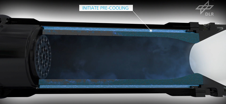
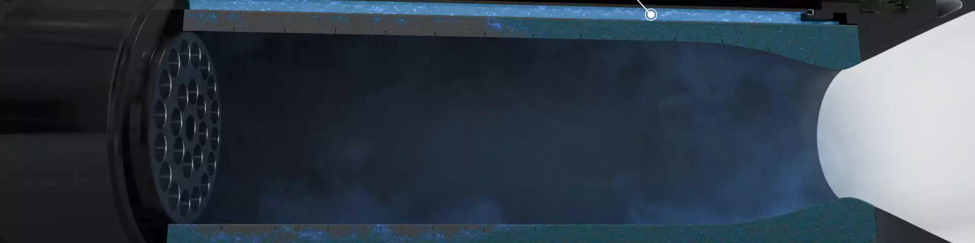
Fig. 2. Transpiration cooling
Microporous OCTRA ceramic matrix composite (CMC) enables cryogenic fuel to transpire through the combustion chamber inner liner to also function as efficient coolant. Photo Credit: DLR
But like any other cooling method, transpiration cooling also has drawbacks. “In regenerative cooling, for example, the heated coolant gets fed to the injector head after cooling the combustion chamber, hence the energy in the coolant is not lost,” says Selzer. “The coolant used for transpiration cooling — just like with film cooling — eventually leaves the nozzle unburned, hence you will lose some efficiency. The overall goal while using transpiration cooling is therefore to reduce the required mass flow to optimize the whole system.”
He explains that the materials in Black Engine help reduce that coolant flow, “because you don’t have to have as much cooling thanks to the higher temperature capability of the CMC materials versus metals. Our aim is to get the amount of cooling to levels with only a small impact on the efficiency. And then you have other advantages from the CMC, such as very low CTE, which gives us an advantage with longer lifetime and higher reliability.”
“Also, the pressure loss for engines using regenerative cooling can be very high,” he continues. “Your turbo pumps have to provide a very high pressure, while the transpiration cooling doesn’t need that. Basically, you can use the transpiration cooling at a pressure that’s the same as for the injection head. And because you don’t have to have as much pressure, you can downsize to smaller turbo pumps. That’s another inherent advantage of this cooling technique.”
Seiler gives an example: “For our 70-bar combustion chamber, we only need 5-7 bar of pressure for the coolant flow, and that’s what you would need for the injector anyway, so basically we need no additional pressure for cooling. With regeneratively cooled systems, the pressure needed just for cooling is usually 10-20% of the chamber pressure. With transpiration cooling, you can use that to downsize the turbo pumps or increase the chamber pressure which results in higher engine performance.”
OCTRA: Porous CMC for transpiration cooling
The German Aerospace Center (DLR) Institute of Structures and Design has decades of experience manufacturing carbon fiber-reinforced carbon matrix (C/C) CMC. Although C/C offers a porous microstructure beneficial for transpiration cooling, it also has lower oxidation resistance and mechanical properties compared to CMC using a silicon carbide matrix. Thus, DLR sought to create a new material with the porosity and permeability of C/C but with improved oxidation resistance.
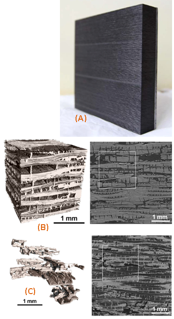
Fig. 3. OCTRA panel, pore structure
OCTRA panel for ultrasonic absorption properties testing (A). Micro computed tomography (CT) scans of OCTRA 40 are shown below (B, C) with negative 3D images of the pore structure at left. The 30%vol porosity in the C/C state (B) is reduced to 10%vol in the C/C-SiC state (C). Pore channels are entirely covered by SiC and become smoother during LSI. Photo Credit: DLR
The new CMC is called OCTRA, and represents a family of products with a range of porosities. Manufacturing begins by creating a green body (composite before carbonization) that uses aramid fiber in addition to carbon fiber as reinforcement. In the subsequent pyrolysis step, the aramid fiber disintegrates, allowing selective insertion of cavities into the CMC. The resulting porosity in OCTRA is tailored by changing the ratio of carbon and hybrid carbon/aramid plies or by changing the content of aramid in the hybrid plies.
The composite green body may be produced using resin transfer molding (RTM), autoclave cure, hot pressing or filament winding. In one example, the OCTRA green body was produced using a hybrid carbon fiber (61%) and aramid fiber (39%) woven twill fabric (ECC Fabrics, Heek, Germany), laid up to form an orthotropic, symmetric laminate, and impregnated with phenolic resin for a 57% fiber content, followed by cure. Phenolic was used because it provides sufficient carbon content in the matrix to produce the necessary C/C material during carbonization.
In the second step, the OCTRA green body was carbonized in an inert nitrogen atmosphere at roughly 1,600°C to convert the phenolic matrix to amorphous carbon. This pyrolysis eliminates the aramid fiber and results in a ≈10% shrinkage mainly in laminate thickness, creating a microscopic network of cracks in the resulting C/C composite with the carbon fibers intact.
In the third step, the C/C component was siliconized via melt infiltration/liquid silicon infiltration (LSI). The component was placed into a coated graphite crucible and granulated silicon was added and heated to >1,420°C to melt the silicon, which then infiltrated the porous C/C component. In an exothermic reaction between the molten silicon and the amorphic carbon matrix, silicon carbide was formed along the microcracks encapsulating the carbon fibers. Siliconization was completed under vacuum at 1,650°C to produce the final C/C-SiC composite.
Porosity can be up to 45% by volume in the C/C intermediate state and 10-25% by volume in the final C/C-SiC composite. Although OCTRA cannot achieve the mechanical properties of dense C/C or C/C-SiC materials, due to its high porosity, tensile strength of 25-50 megapascals and flexural strength of 75-100 megapascals are possible. Mechanical properties can be increased by reducing the amount and diameter of microcrack pores, which in turn can be influenced by the resin and process used in the green body.
In addition to transpiration cooling, OCTRA can be used for ultrasonically absorptive thermal protection system (TPS) materials that provide damping and boundary layer stabilization for improved performance in hypersonic vehicles. For example, OCTRA CMC materials are being considered for use in a passively cooled combustor design for the HIFiRE 8 joint Australia/AFRL (Air Force Research Lab, Wright-Patterson Air Force Base, Ohio, U.S.) hypersonic flight program, expected to fly at Mach 7 for roughly 30 seconds. Compared to using actively cooled metal structures, OCTRA CMC may provide significant weight savings in such scramjet structures.4
Dual-shell CMC nozzle and interface design
The CMC rocket nozzle is not made from OCTRA. For higher temperature resistance, it uses instead Nextel aluminum-oxide (Al2O3) ceramic fiber from 3M (Minneapolis, Minn., U.S.) and a hybrid matrix of Al2O3 and yttria stabilized zirconia (3YSZ) manufactured by Inovaceram (Sachsenheim, Germany). The nozzle comprises the inner nozzle cone and exterior nozzle extension, each made from a different Nextel fiber. The inner nozzle cone begins 15 millimeters after the nozzle throat and is made using Nextel 720 fabric and is designed to resist temperatures of more than 1,150°C during the minutes-long rocket launches. The nozzle extension is made from Nextel 610 fabric, bolted to the combustion chamber cylinder and designed for strength. This dual-shell construction, similar to the use of multiple composites in the combustion chamber, enables decoupling of thermal and structural loads in the nozzle. “And in the nozzle we also don't have much need for cooling,” says Selzer, “because of the transpiration cooling film and the temperature resistance of the CMC.”
Another key aspect of the design is the nozzle attachment interface. “The nozzle is designed with pockets that allow us to affix it to the combustion chamber using bolts shaped like dovetail joints,” says Selzer. “These fit into the pockets and connect from the combustion chamber through the nozzle flange in a way that allows thermal expansion.” In other words, explains Seiler, “You install it at the size it was manufactured, but when the engine is fired, the nozzle expands. Our interface design allows the nozzle and bolts to expand without interrupting the joint. It handles the CTE and also lowers weight.”
New models, tests and future developments
The work DLR has completed to get this far is nontrivial. For example, the team had to develop a computational fluid dynamics (CFD) model to predict the thermal and pressure loads. These loads are then used in a FEM analysis of the thrust chamber.5 For CFD, the team used the industry-standard CFX v17.2 software from Ansys (Canonsburg, Pa., U.S.). The FEM analysis uses Ansys Workbench 2019 R3. To determine the contour of the rocket thrust chamber, DLR used Rocket Propulsion Analysis (RPA, Rocket Propulsion Software+Engineering UG, Neunkirchen-Seelscheid, Germany). The results from RPA were used to validate the mainstream domain solved in Ansys CFX.6
Though ground testing of a full-scale Black Engine was slated to begin early in Q1 2022, the program has been slowed by the COVID-19 pandemic and the development of the new mobile test bench. The latter is key for commercialization by DLR’s project partners at BEA, says Selzer, “because it can be carried all over the world, so that if someone wants to buy this type of engine and to see a live test before finalizing a commitment, it will now be possible to give them that live demonstration within a few weeks, for example.” The test bench alone is a complex project, he adds, “but so is our development of this new design along with a new combination of materials. We are planning to have the test bench experiments start soon and completed in 2022.”
And yet, even while pushing Black Engine forward in TRL, the team is already anticipating further optimization and performance enhancement enabled by this novel design. “So, the next thing would be to optimize the whole system,” says Selzer, “to lower the required coolant amount by tailoring the CMC to the thermal profile during engine burn. Right now, we use the same CMC throughout the combustion liner. But by using our stacked rings design, we could use different CMC materials in different locations. For example, the heat loads are highest in the nozzle throat but lower elsewhere. So, we could tailor the CMC permeability to the liner thermal loads in each area, which would then tailor the coolant flow, and better optimize the chamber as a whole.”
The team has also developed a second iteration of the combustion chamber, which uses a revolutionary hyperboloid geometry instead of the industry-standard cylinder tapering into a Laval throat at the nozzle.5 A Laval nozzle has an asymmetric hourglass shape, where the narrowed and elongated aft section is used to accelerate the hot, pressurized gas exiting the combustion chamber to increase thrust. “The hyperboloid design makes the hot gas flow much more turbulence-free in the nozzle throat area,” says Seiler, “and thus leads to lower heat load peaks in this critical flow section. In addition, cooling and fuel injection can be combined in the annular combustion zone adjacent to the injector head, which can increase engine efficiency.”
For now, says Selzer, “our focus in the current project is on qualifying the cylindrical combustion chamber and classical nozzle contour. The hyperboloid combustion chamber might be developed and built by BEA.” He emphasizes that advancing the current iteration of Black Engine technology to TRL 5 offers significant benefits. “The improvements we are targeting in efficiency, reliability, weight, cost and reusability have the potential to enable rocket engines with higher lifetime and lower maintenance standards compared to current rocket engines. And that has the potential to further decrease the cost for access to space.”
REFERENCES
1Hermann Hald, Markus Ortelt, Ingo Fischer, Dirk Greuel and O. Haidn. "Effusion Cooled CMC Rocket Combustion Chamber," AIAA 2005-3229. AIAA/CIRA 13th International Space Planes and Hypersonics Systems and Technologies Conference. May 2005.
2Markus Ortelt, H. Elsaesser, Armin Herbertz, I. Mueller and Hermann Hald. "Structural Investigations on Cryogenically Operated and Transpiration Cooled Fiber Reinforced Rocket Thrust Chambers," AIAA 2012-4010. 48th AIAA/ASME/SAE/ASEE Joint Propulsion Conference & Exhibit. July 2012.
3Christian Dittert and Marius Küttemeyer, “Octra - Optimized Ceramic for Hypersonic Application with Transpiration Cooling,” published in the book: Advances in High Temperature Ceramic Matrix Composites and Materials for Sustainable Development; Ceramic Transactions, Volume CCLXIII. July 2017. 10.1002/9781119407270.ch37
4D. Glass, D. Capriotti, T. Reimer, et. al., “Testing of DLR C/C-SiC and C/C for HIFiRE 8 scramjet combustor,” 7th European Workshop on Thermal Protection Systems and Hot Structures, April 2013. 10.2514/6.2014-3089
5D. Munk, M. Selzer, H. Seiler, et. al., “Analysis of a transpiration cooled LOX/CH4 rocket thrust chamber,” International Journal of Heat and Mass Transfer, vol 182, published Sep 2021. 10.1016/j.ijheatmasstransfer.2021.121986
6M. Ortelt, H. Seiler, M. Boehle, D. Munk, “Black Engine Ceramic Rocket Propulsion,” 70th International Astronautical Congress (IAC), Washington, D.C., U.S., Oct 21-25, 2019.


.jpg;maxWidth=300;quality=90;format=webp)


Related Content

Demonstrating composite LH2 tanks for commercial aircraft
Toray Advanced Composites and NLR discuss the Netherlands consortium and its 4-year project to build demonstrator liquid hydrogen tanks, focusing on thermoset and thermoplastic composites.
Read More
Multi-material steel/composite leaf spring targets lightweight, high-volume applications
Rassini International was challenged by Ford Motor Co. to take weight out of the F-150 pickup truck. Rassini responded with a multi-material steel/composite hybrid leaf spring system that can be manufactured at high volumes.
Read More
One-piece, one-shot, 17-meter wing spar for high-rate aircraft manufacture
GKN Aerospace has spent the last five years developing materials strategies and resin transfer molding (RTM) for an aircraft trailing edge wing spar for the Airbus Wing of Tomorrow program.
Read More
JEC World 2022, Part 3: Emphasizing emerging markets, thermoplastics and carbon fiber
CW editor-in-chief Jeff Sloan identifies companies exhibiting at JEC World 2022 that are advancing both materials and technologies for the growing AAM, hydrogen, automotive and sustainability markets.
Read MoreRead Next

Rocket engine thrust frame proves a strong candidate for composites conversion
The engine thrust frame of a space launch vehicle, located at the bottom of a rocket stage, joining fuel tanks to engines, must deliver strength and stiffness across a range of temperatures — cost-effectively.
Read More
The Alpha launch vehicle: Designing performance in, cost out
Firefly Aerospace’s Alpha 2.0 launch vehicle, designed to deliver satellites into low Earth orbit, gets a composites makeover in pursuit of larger payload capacity and more cost-effective performance.
Read More
Rocket Lab unveils composite Neutron launch vehicle
Live streamed web event reveals detailed Neutron rocket architecture for the first time, including its carbon fiber launch vehicle and second stage, and new Archimedes rocket engine, all designed for reliability and reusability.
Read More