
More details on MAI Skelett design process
The MAI Skelett project developed a thermoplastic composite roof structure that outperforms carbon fiber/epoxy design, including crash load level, energy absoprtion and BIW integrity.


The CW April 2019 feature “Skeleton design for more competitive composite auto structures” discusses the “skeleton” design approach of using thermoplastic overmolded composite pultrusions to improve material efficiency, cycle time and cost in automotive structural components. The windshield frame component highlighted is a demonstrator designed and fabricated as part of the MAI Skelett project, completed by MAI Carbon, a regional division of the Carbon Composites e.V. (Augsburg) network, and led by BMW (Munich, Germany). During my research for this article, I was able to study the project’s final report. This blog is a summary, including aspects that I found particularly interesting.
MAI Skelett project
This project ran from the beginning of 2014 to mid-2015. Partners included BMW, CirComp (Kaiserslautern) for pultrusions, Eckerle (Beilngries) for injection molding and tooling, P+Z Engineering (Munich) for simulation and design optimization and SGL Carbon for materials.


A quick note about the project coordinator, MAI Carbon: Referred to as the Leading-Edge Cluster MAI Carbon, it focuses on the triangle region formed by the cities Munich, Augsburg and Ingolstadt, and pursues the objective to lead CFRP technology to series capacity by 2020. “In order to achieve this goal, quantum leap innovations are required along the complete component-part life cycle, i.e. starting from the fiber and matrix material, through the manufacture of the component parts and product systems, to the stage of conclusive recycling concepts.” — MAI Carbon website
BMW issued the final report on the MAI Skelett project in April 2015.
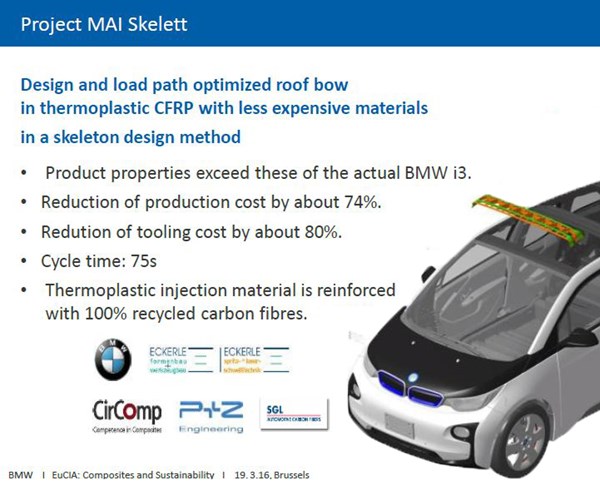
SOURCE: BMW presentation at EuCIA 2016 Brussels
Windshield frame demonstrator
The objective of the MAI Skelett project was to demonstrate the skeleton design approach to produce an inexpensive composite roof bow. That component evolved so that the design basis was the BMW i3 front roof bow/roof frame, which BMW also refers to as a roof cowl. This body-in-white (BIW) component forms the transverse support between the A pillars and supports the windscreen/front windshield as well as the interior sun visor and exterior body panel (cover) and sun roof (sliding lifting roof). See Fig. 7 below.
The skeleton design approach uses unidirectional 50K carbon fiber-reinforced thermoplastic pultruded bars (black features in diagram below) as the main load-carrying elements, held together by thermoplastic composite overmolding, which also provides functional geometries for stiffening ribs, clips and attachments, etc.
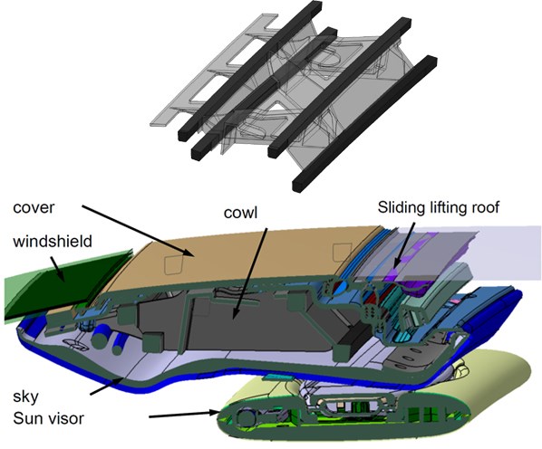
The top figure represents the “cowl” in the assembly diagram above where continuous carbon fiber-reinforced thermoplastic pultrusions (black bars top and green squares at center of bottom image) form the main load-carrying elements, overmolded by short fiber-reinforced thermoplastic compound. SOURCE: Fig. 7, MAI Skelett final report
Construction concept to part design
The first step was to generate material properties for structural modeling and analysis. Samples of injection-molded materials were evaluated in tensile, bending, impact, fiber content and fiber length tests per German DIN standards. The 10mm x 10mm square cross section for the pultrusions was defined and properties calculated from data sheets. These inputs would be validated and refined throughout the project as both materials and component design were tested and iterated.
Eckerle performed initial injection molding simulations to explore different materials, filling time, injection pressure, deformation, etc. Working in collaboration with designers from BMW and P + Z Engineering, the overmolding design was developed and optimized.
P + Z Engineering began finite element (FE) modelling and simulation using different load cases based on static rigidity analysis of bending and torsion and dynamic stiffness tests using modal frequency response. The goal was to compare the skeleton design with the current CFRP component. Load cases were also derived from passive safety requirements such as the roof push test (rollover protection) and sideways pole crash test.
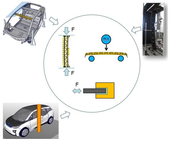
Derivation of loads based on passive safety requirements.
SOURCE: Fig. 33, MAI Skelett final report (P+Z Engineering)
For this passive safety performance, the model was extended to a partial model of the entire vehicle. The vehicle body (A and B-pillars, roof frame and windshield) needs sufficient resistance to crash loads without excessive deflection to prevent intrusion and contact with the driver/passenger’s head. The pole crash simulates a lateral impact of the vehicle against a fixed object, where the car body must withstand high local stress and resist high depth of intrusion while maintaining structural integrity. Results showed that the skeleton design was comparable to the current CFRP structure, including similar intrusion depth, and could be enhanced by changing the thickness and composition of the materials.
In both safety tests, the windshield frame functions mainly as a force-transmitting connection between the A-pillars or roof longitudinals. It was observed that the cross-sectional configuration of the pultruded bars, especially at the reshaped ends — which was required for connections, see Pultruding and thermoforming structural elements below — significantly determined the amount of load that could be transferred and overall component deformation. Thus, the goal was to optimize the deformation and bending behavior, which would, in turn, affect the final shape of the pultruded bars and overall production process for the part.
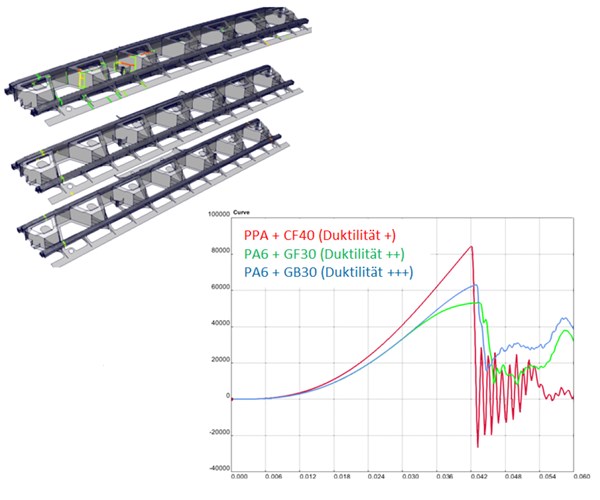
Influence of overmolding material on ductile failure mode for windshield frame
SOURCE: Fig. 38, MAI Skelett final report (P+Z Engineering)
Different materials for pultrusions plus overmolding were evaluated to explore a more ductile failure mode for the component. Although this ductile failure mode decreased the amount of load the windshield frame could transfer, it improved the structural integrity of the BIW as a whole. Further studies explored the structural behavior of the entire system, integrating connections between the pultruded bars and overmolding compound.
Analysis methods included solid modelling, rebar modelling (geometry modelling where the pultrusions act as rebar reinforcing the overmolding) and modelling using shell elements, as well as various combinations. Software included the FE solver ABAQUS (Dassault Systèmes, Paris, France) and Dakota parameter solver developed by Sandia National Lab (Albuquerque, NM, US). OptiStruct (Altair Engineering, Troy, MI, US) was used for topology optimization, which also helped to finalize shape and placement of the pultruded bars.
Pultruding and thermoforming structural elements
Because 50K tow is characterized by tight packing of myriad filaments (50,000), spreading the tow was a key step, integrated into the pultrusion process to optimize impregnation of the fibers with the thermoplastic. Various types of PA6 were also investigated to determine the required viscosity and rheology for optimizing process quality and speed.
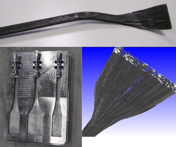
Three different shapes were trialed for thermoforming the ends of the pultruded bars.
Those stretched in the direction of the matrix flow maintained the best alignment, as verified by CT scans. SOURCE: Figures 22, 23 and 24, MAI Skelett final report (BMW)
After the UD pultruded bars were made on a continuous line at CirComp, they were shipped to BMW Landshut to be thermoformed and then shipped again to Eckerle for injection overmolding. Thermoforming was required to bend and flatten the ends of the bars to meet requirements for connecting the windshield frame component to adjacent components. Three different forming concepts were trialed. It was determined that only when the pultrusions are stretched in the direction of matrix flow was the high strength and stiffness of the fiber realized by keeping it as straight as possible. The thermoformed bars were inspected with computed tomography (CT) to ensure fiber orientation was maintained. An existing thermoforming tool was then modified to continue development trials. It was integrated with existing equipment at BMW to form a fully automated pilot production line, which produced 135 sets of bars (540 bars total).
Overmolding using RCF
Many of MAI Carbon’s projects have included recycling as part of a German industry initiative to increase sustainability in manufacturing. For MAI Skelett, this translated into exploring the use of recycled carbon fiber (RCF) as the reinforcement for the overmolding compound. Initial production of this material was accomplished in a lateral twin-screw extrusion machine. Thermoplastic matrix in the form of PA6 pellets were fed in as well as a 10-cm wide RCF nonwoven mat. The latter was metered continuously into the extruder, which chopped and mixed it with the melted PA6. Two variants — 30% and 40% RCF by weight — were produced and evaluated via mechanical testing. This was part of the initial work completed to provide material properties for the roof rail/windshield frame modelling and simulation.
Filling studies were then performed to understand weld lines, air inclusions and flow behavior. It was determined that both 30% and 40% fiber levels could be processed well and increasing RCF content to 40% only increased modulus. Later trials used a KraussMaffei combination twin-screw extruder/injection molder to enable compounding and overmolding in a single machine. This increased production speed but reduced fiber length, still there was no noticeable degradation in mechanical properties.
Validating performance and process
Completed demonstration parts were evaluated in static and dynamic 3-point bending tests and drop tower tests for dynamic loading (axial crush testing). Though results of static testing agreed well with simulation results, dynamic testing revealed undetected defects in the pultruded bars — mainly dry spots — which caused a significant deviation in actual part performance vs. simulation. The connection of the bars to the overmolding material also contributed to the mechanics of failure and deflection in the windshield frame during testing. Here again, a more ductile (lower modulus) molding compound showed the best performance in terms of residual strength and structural integrity.
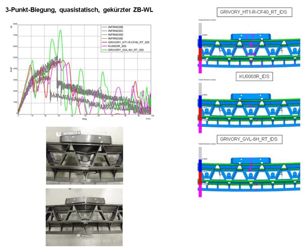
Three-point bending tests using quasi-static loading (vs. dynamic) showed good agreement with simulations and were used to evaluate different materials.
SOURCE: Fig. 38, MAI Skelett final report (P+Z Engineering)
Windshield frame demonstrators were optically measured for dimensional stability and found to have only slight deviations which could be easily addressed by amending the overmolding tool. Realistic cycle times were evaluated with pultruded bar thermoforming being 9 seconds faster than overmolding. Integrating both processes was deemed necessary to reach a 75-second cycle time for production volumes on par with the BMW i3 model.
Final simulation and test results showed that the skeleton components exceeded all requirements for the current CFRP part except for torsional stiffness, which was determined not to be a key design driver for the windshield frame anyway. Regarding load level and energy absorption in crash load cases, the skeleton design exceeded the current CFRP part. It also succeeded in achieving a more ductile failure mode, which further advances not only composite structure crash performance but also the understanding of that crash performance and how it relates to the BIW structure as a whole.
The skeleton windshield frame also demonstrates the next step in CFRP design and production, reducing cycle time and waste via pultrusion and overmolding, as well as a minimized, more efficient use of carbon fiber through unidirectional load-carrying elements. Increased sustainability is demonstrated by reusing production waste from other CFRP parts in the overmolding compound while improving this part’s functionality and performance.


.jpg;maxWidth=300;quality=90;format=webp)
Related Content

RUAG rebrands as Beyond Gravity, boosts CFRP satellite dispenser capacity
NEW smart factory in Linköping will double production and use sensors, data analytics for real-time quality control — CW talks with Holger Wentscher, Beyond Gravity’s head of launcher programs.
Read More
PEEK vs. PEKK vs. PAEK and continuous compression molding
Suppliers of thermoplastics and carbon fiber chime in regarding PEEK vs. PEKK, and now PAEK, as well as in-situ consolidation — the supply chain for thermoplastic tape composites continues to evolve.
Read More
Plant tour: Albany Engineered Composites, Rochester, N.H., U.S.
Efficient, high-quality, well-controlled composites manufacturing at volume is the mantra for this 3D weaving specialist.
Read More
Novel composite technology replaces welded joints in tubular structures
The Tree Composites TC-joint replaces traditional welding in jacket foundations for offshore wind turbine generator applications, advancing the world’s quest for fast, sustainable energy deployment.
Read MoreRead Next

CW’s 2024 Top Shops survey offers new approach to benchmarking
Respondents that complete the survey by April 30, 2024, have the chance to be recognized as an honoree.
Read More
Composites end markets: Energy (2024)
Composites are used widely in oil/gas, wind and other renewable energy applications. Despite market challenges, growth potential and innovation for composites continue.
Read More
From the CW Archives: The tale of the thermoplastic cryotank
In 2006, guest columnist Bob Hartunian related the story of his efforts two decades prior, while at McDonnell Douglas, to develop a thermoplastic composite crytank for hydrogen storage. He learned a lot of lessons.
Read More