
.jpg;width=70;height=70;mode=crop;format=webp)


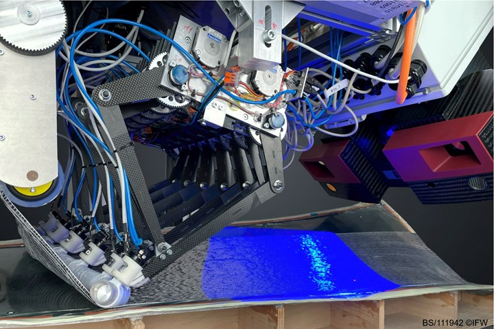
Fig. 1. The Institute for Production Engineering and Machine Tools (IFW) at Leibniz University Hannover developed an automated draping system for dry fiber layup through project FlexProCFK. In the current project AutoBLADE, IFW is proving out the technology on a tidal rotor blade mold. The main focus for the pictured experiment was measuring deformation and accurate layup according to the mold geometry. A GOM Atos measuring system (pictured at right, in red) is capturing data on the draped material via 3D scan. An internally developed calculation method is used to determine the fiber orientation of the deposited material. Photo Credit, all images: IFW
Dry fiber fabrics such as noncrimp fabrics (NCF) are popular in composites manufacturing because, compared to prepreg materials, they are relatively less expensive, easier to store and transport and can be processed using a variety of methods. However, draping dry fabrics over complex part shapes can be difficult at best, often resulting in creasing or wrinkling. Ongoing research efforts at the Institute for Production Engineering and Machine Tools (IFW) at Leibniz University Hannover (Hannover, Germany) aim to both simplify and automate this process with a robot-mounted, modular draping system that so far has been demonstrated on aerospace and tidal energy components.
FlexProCFK: Developing an automated draping system
FlexProCFK was a four-year project that took place from 2016-2020, involving researchers from IFW in cooperation with the Institute of Polymer Materials and Plastics Engineering (PuK) at the Technical University of Clausthal (Clausthal-Zellerfeld, Germany) and the Institute of Aircraft Design and Lightweight Structures (IFL) at the Technical University of Braunschweig (Germany), all of which have research teams based at the CFK Nord Research Center in Stade, Germany. Funded by the European Regional Development Fund, the goal of the project was to develop a technology for continuous wet draping of dry textiles for components with complex geometries.


According to Simon Werner, research assistant of CFRP production technologies at IFW, the project was instigated by aerospace part design research and development (R&D) being done at IFL: “Our colleagues developed a new, unconventional structural concept for an aircraft fuselage with an integral grid-like stiffening concept. The basic idea was to create a bionic-inspired shape to be manufactured in only one autoclave cycle. This implies the manufacturing of fuselage skin and stiffening structure within one process step. But at that time, there was no automated production process to build the stiffening structures directly onto the fuselage skins.”
Meanwhile, IFW had already been working on automated layup concepts and, following previous successful collaborations between IFW and IFL, Werner and his team at IFW were brought into the FlexProCFK project to adapt their automated layup concepts for IFL’s fuselage design. Over the next few years, the IFW team developed the new manufacturing technology, while their partners at PuK investigated combinations of drapable fabrics and resin impregnation to suit design requirements.
Specifically, FlexProCFK was focused on developing an automated process to integrate stiffeners directly onto a fuselage skin, by laying up a reinforcement textile over double curved foam cores placed onto the skin. Using dry fabrics in combination with in-process resin impregnation was decided upon over traditional prepregs as a more cost-effective material option that also allows a higher degree of geometrical freedom to the structural design.
The modular draping system that the researchers developed involves three steps. First, the textile is cut into its desired contour corresponding to the stiffener geometry, followed by the second step, impregnation with a thermoset resin via spray nozzles. For FlexProCFK, a one-component (1K) epoxy resin was sprayed onto one side of the fabric before layup.
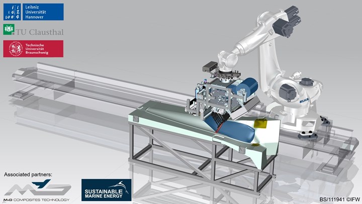
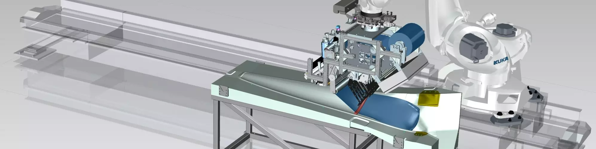
Fig. 2. This simulation shows IFW’s automated draping system module in its production environment. Situated on a robotic arm, the laying head is developed to lay down dry fabric on complex geometry molds. In this image, the mold is for a 2-meter-long tidal turbine rotor blade in project AutoBLADE.
“At the start, we wanted to accomplish complete impregnation of the textile to achieve a uniform distribution of fibers and resin,” Werner says. However, using liquid resin during layup proved difficult to control, and can be difficult to remove if it comes into contact with the machine itself, he says. He notes that laboratory investigations showed that sufficient impregnation could be achieved by applying resin to only one side of the part and then curing via autoclave. “So, we hereupon only spray it on the bottom of the textile before it’s draped and consolidated onto the foam core. This has additional advantages in terms of stickiness and it adheres very well to the core,” Werner explains.
After resin impregnation, a robotic arm-mounted draping unit places the impregnated textile on top of the foam core stiffeners situated on top of the fuselage skin. The draping unit consists of a silicone tube divided into six pneumatic segments that can be pressurized independently, and seven scissor-shaped kinematic arms that serve to position the tube. The final shape and movement of the tube along the layup surface is generated via Matlab software in accordance with the part geometry.
One challenge to the overall system design, Werner says, was making sure the silicone tube could hold the fabric in equal tension across the surface while consolidating, to avoid wrinkling and creasing. The tube was developed to be a particular shape — he calls it a “draping spline” — to hold the tension equally across the width of the fabric.
Finally, after the draping process is complete, the structure is ready for vacuum bagging and autoclave cure.
The end result of FlexProCFK was a working prototype version of the automated draping system. The next step, begun in spring 2021, has been trying out the system on a real application, called project AutoBLADE.
AutoBLADE: Optimizing manufacture of infused tidal rotor blades
The second IFW-led project, also funded by the European Regional Development Fund, is scheduled to last 18 months from April 2021 to July 2022. For AutoBLADE, IFW is working again with PuK and IFL along with industrial partners M&D Composites Technology GmbH (Friedeburg, Germany) and Schottel Hydro GmbH (Spay, Germany, now part of Sustainable Marine Energy Ltd.).
“AutoBLADE is basically the follow-up project from FlexProCFK,” explains Marco Bogenschütz, research assistant at IFW and leader of the IFW subproject in AutoBLADE. This time, IFW is working with hydrokinetic and tidal energy systems manufacturer Schottel Hydro GmbH to investigate the use of its automated draping system prototype for producing approximately 2.5-meter-long, 400-millimeter-wide tidal turbine rotor blades. M&D Composites Technology GmbH designed the aluminum blade molds, which are equipped with a heating system for improved resin infusion and post cure (see Figs. 1 and 2). Bogenschütz notes that part of the goal is to figure out what other improvements need to be developed in future projects, with the ultimate objective of scaling up the process in terms of layup speed and part size for cost-effective production of wind turbine blades and other large structures. “With AutoBLADE, we want to find the limits of our technology,” he says.
One focus of AutoBLADE is the system’s layup speed. Werner notes, “Compared to the FlexProCFK project, however, the geometry of the turbine blade is less complex. As a result, we should be able to achieve higher deposit speeds in this project.”
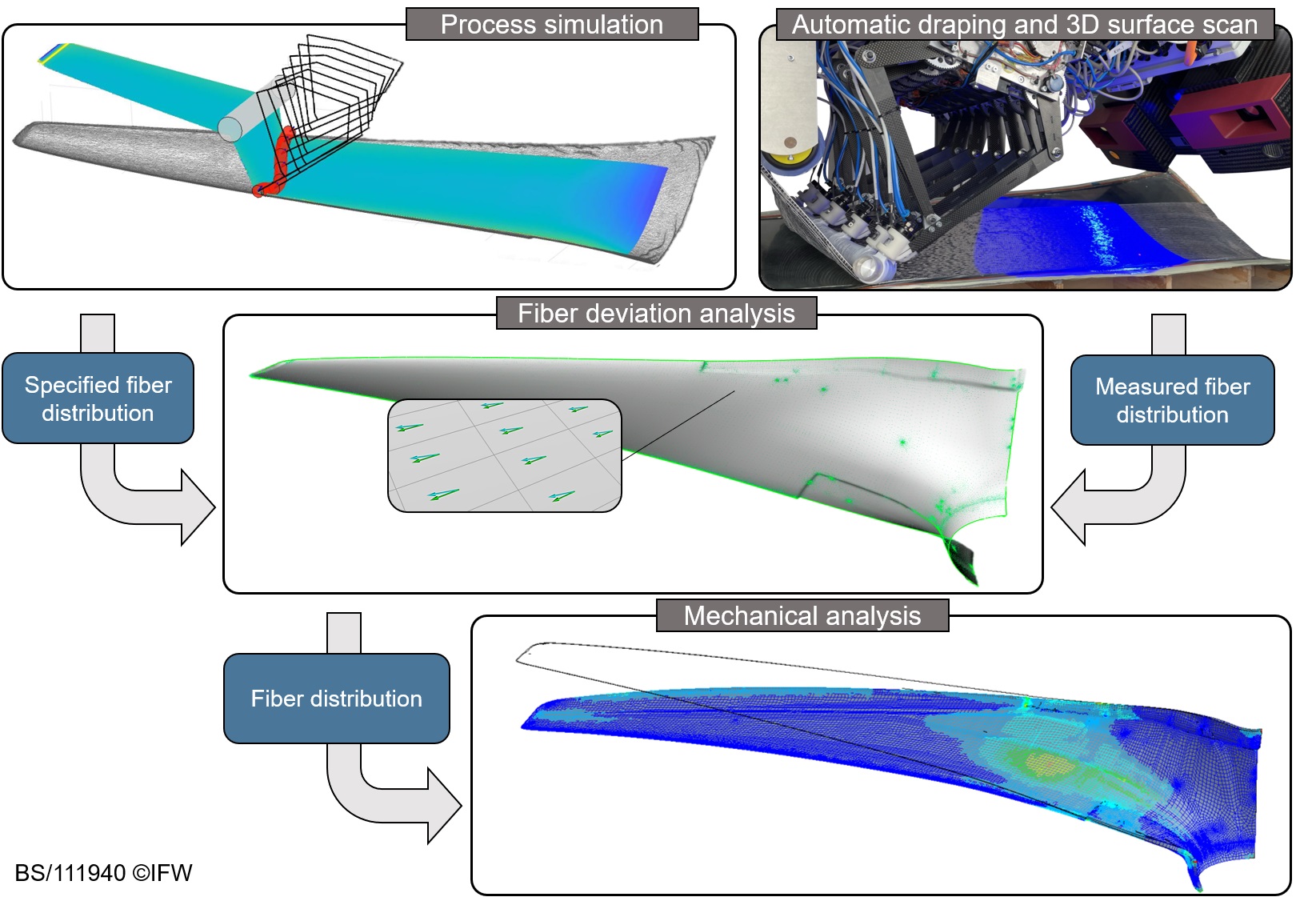
Fig. 3. The process development for AutoBLADE is largely informed by process simulation and analysis. For each layup experiment, the process is first simulated virtually via Matlab, then scanned via a 3D surface scanner during actual layup. From this scan, the fiber orientation of individual patches over the blade geometry are calculated, from which deviations can be determined between the fiber angle that actually occurs and the one assumed during design. A finite element (FE) simulation is then used to investigate the influence of the fiber angle deviations on the mechanical properties of the rotor blade.
The new project has necessitated several changes in the process, allowing the IFW team to demonstrate the customization possible with their technology. For example, whereas the aerospace demonstrator part in FlexProCFK was fabricated via a sprayed-on resin cured via autoclave, in AutoBLADE, the dry fiber preforms are treated only with a binder before layup over the mold, and then impregnated via vacuum infusion afterwards. This change, Bogenschütz notes, eliminates issues the FlexProCFK team had with spraying liquid resin during the automated layup process. In addition, AutoBLADE is investigating use of both unidirectional (UD) and bidirectional NCFs.
There are three main parts to the project, Bogenschütz explains (see Fig. 3). First, the team worked with project partners to characterize the part parameters and requirements and determine a method for evaluation. “The first part of AutoBLADE was basically on how we can measure fiber directions on what we laid up,” Werner explains. Finite element (FE) models are used to predict the behavior of the fabric during layup, then a GOM (Braunschweig, Germany) Atos 3D scanner captures data during actual layup experiments. From this data, the AutoBLADE team calculates the fiber orientation of the fabric that has been laid down, from which they can determine whether there are any deviations between the actual layup and the model. This evaluation method will also help to improve the layup quality, Werner explains, “not only in the geometrical form, but also in the fiber structure.”
Second, in summer 2021, the researchers began draping experiments themselves — first making molds based on geometry from Schottel Hydro, followed by layup experiments using the automated draping system prototype. Currently, Bogenschütz says layup experiments are ongoing, testing the technology with different material samples and using a binder material to hold the dry fiber fabrics in place. The material samples, he says, include UD (0°), bidirectional (±45° and 0°/90°) NCFs with different percentages of binder. The third step will be to develop an optimized manufacturing process for the finished rotor blade.
Beyond AutoBLADE, Bogenschütz and Werner hope to continue optimizing and perfecting the automated draping process for larger parts and applications in other fields, as well.


.jpg;maxWidth=300;quality=90;format=webp)


Related Content

The state of recycled carbon fiber
As the need for carbon fiber rises, can recycling fill the gap?
Read More
Novel dry tape for liquid molded composites
MTorres seeks to enable next-gen aircraft and open new markets for composites with low-cost, high-permeability tapes and versatile, high-speed production lines.
Read More
Infinite Composites: Type V tanks for space, hydrogen, automotive and more
After a decade of proving its linerless, weight-saving composite tanks with NASA and more than 30 aerospace companies, this CryoSphere pioneer is scaling for growth in commercial space and sustainable transportation on Earth.
Read More
Materials & Processes: Composites fibers and resins
Compared to legacy materials like steel, aluminum, iron and titanium, composites are still coming of age, and only just now are being better understood by design and manufacturing engineers. However, composites’ physical properties — combined with unbeatable light weight — make them undeniably attractive.
Read MoreRead Next

From the CW Archives: The tale of the thermoplastic cryotank
In 2006, guest columnist Bob Hartunian related the story of his efforts two decades prior, while at McDonnell Douglas, to develop a thermoplastic composite crytank for hydrogen storage. He learned a lot of lessons.
Read More
Composites end markets: Energy (2024)
Composites are used widely in oil/gas, wind and other renewable energy applications. Despite market challenges, growth potential and innovation for composites continue.
Read More
CW’s 2024 Top Shops survey offers new approach to benchmarking
Respondents that complete the survey by April 30, 2024, have the chance to be recognized as an honoree.
Read More