
Laser projection system simplifies helicopter assembly
Eurocopter uses an automated laser placement system for assembly of aircraft fuselages and airframes.


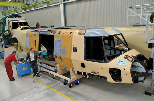
Eurocopter uses SL-Laser Systems laser placement system for assembly.
In the process of aircraft assembly, a huge number of brackets, fasteners and other small parts must be attached to the airframe. Traditionally, each part is printed out from the 3-D computer design file to a paper document that lists its spatial coordinates as well as a part description and other nongeometric information. Placement of each part typically requires tedious manual copying, coordinate measuring and marking using expensive templates, and the process remains time-consuming and error-prone.
For NH90 fuselage and airframe assembly at Eurocopter (Marignane, France), however, SL-Laser Systems LP (Charlotte, N.C. and Traunreut, Germany) has supplied an improved and reliable alternative: the SL-Laser ProDirector 4/XS laser placement system, equipped with its SL3D V4.0 software package. Mounted on a heavy-duty tripod, the system first imports 3-D design data from any industry-common CAD program (the software runs on any standard Windows-based PC or laptop) and then the SL3D software scans the data file and does a “smart recognition” of similar part geometries. Like objects are identified and assigned a common part name. Next, all or only selected parts are exported, and a library with all part types is created by a simple mouse click. The library, assembled in SL-Laser’s proprietary *.sl file format as well as a set of *.iges files, serves as a starting point for the creation of the final projection symbols.
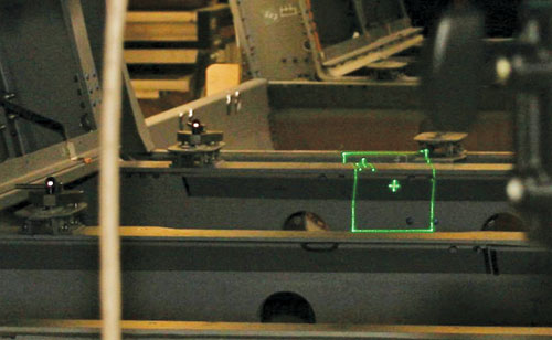
Using SL3D, Eurocopter technicians quickly replace the complex part geometries with simplified symbols that show only the relevant surfaces and contours necessary to accurately place the part. Calibration is accomplished by searching for six to eight reflective reference points with known coordinates. When calibrated, the system can project symbols and fasteners, or assemblies can be precisely located and attached. Projected symbols are based on two distinct assembly strategies: For part location and marking, only the bottom surface geometry of the part drawing is used. For immediate part attachment to the projected laser image, only the top surface of the part is needed for proper alignment. Each part’s CAD drawing can be quickly modified to create the selected projected image, again, with a couple of mouse clicks. Parts in the CAD file are automatically replaced with the simplified symbols and marked with “!”
The system also can be used for quality-control checking after assembly. Its small footprint offers high portability and flexibility yet reportedly maintains the same precision and speed of larger SL-Laser projectors.


