
Is the BMW 7 Series the future of autocomposites?
BMW AG's Dingolfing, Germany, auto manufacturing facility is well known for churning out a variety of car models and types, and the 7 Series is among them, famous for its steel/aluminum/composites construction. Does this car represent the optimum of composites use in vehiicles? This plant tour of the Dingolfing plant looks at how composites on the 7 Series come together.


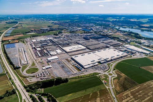
BMW AG’s (Munich, Germany) largest manufacturing site in Europe — in area (2.8 million m2) and volume (360,000 cars in 2015) is situated in Dingolfing, Germany. More than 17,000 employees — 12,000 in the plant and another 5,000 in surrounding support facilities — turn out 1,600 cars per day. Dingolfing not only produces 15 different models, including all variations of BMW’s 5, 6 and 7 Series, but also one model each of the 3 and 4 Series. It also turns out components for BMW’s electric vehicles and, as the company’s Center of Competence for aluminum, it builds car bodies for Rolls-Royce (Manchester, UK) as well.
“We’ve learned how to handle complexity,” emphasizes Plant Dingolfing managing director Josef Kerscher. “We are the only automotive manufacturing facility worldwide to handle not only this many different models, but also engines from three to 12 cylinders, as well as plug-in hybrids.”


The Dingolfing complex began as the Hans Glas GmbH auto factory, which BMW acquired in 1967. Since 1973, BMW has produced almost 10 million vehicles there. Over the past three years, Dingolfing has undergone an upgrade valued at more than a half billion euros for the new 7 Series production alone, including increased automation and aluminum die casting along with a new carbon fiber-reinforced plastic (CFRP) production hall and a new state-of-the-art facility to produce the first body-in-white (BIW) combining steel, aluminum and CFRP, known as the Carbon Core.

BMW 7 Series and BMW i3.
The multi-material BIW is a big reason why the 7 Series is breaking new ground in top-of-the-line vehicle performance and luxury. The BMW 7 Series is 130 kg lighter than its predecessor and its principal competitor, the S-class Mercedes. Although only 3% of the BIW parts are CFRP — totaling 13 kg — they account for 40 kg of weight savings. It contributes to what BMW calls Efficient Dynamics, which reduces fuel consumption and emissions while enhancing the driver experience. “I get 100 km from 4.5 liters of gas,” says Kerscher. “This is what you would expect from a very small car, not from a luxury sedan. The key to this is lightweight construction.”
The BMW 7 Series is now in full production. “The launch was very successful,” says 7 Series product manager Christian Metzger, “achieving cost, quality and volume targets.” The launch was the culmination of a three-year program that included not only product development, but also a three-year process in the plant to develop all of the required manufacturing processes. The latter was CW’s focus as it toured Dingolfing’s 1.6 million-m2 Plant 2.4.
CFRP: 4,000 parts per day
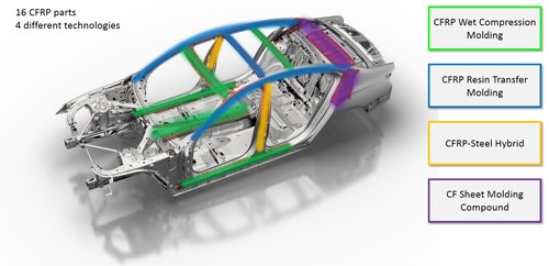
Fig. 1.
Sixteen CFRP parts make up the Carbon Core, each manufactured using one of four technologies (Fig. 1), and each chosen to meet specific part shape and property requirements while minimizing weight. Michael Ahlers, BMW head of Process Chain Body-In-White and Exterior, points out the Carbon Core parts on a 7 Series BIW displayed at the entrance to the plant’s 11,000m2 CFRP production/logistics area. Noting the B-pillar (Fig. 2), Ahlers explains, “It uses CF prepreg covered with a film of epoxy adhesive. Both are hardened to the formed steel B-pillar in one press step.” High-pressure resin transfer molding (HP-RTM) is used in the roof rail — made in the nearby BMW Landshut plant — to meet roof pressure test requirements, while wet compression molding enables cost-effective, short-duration cycle times for parts such as the tunnel, sills and selected roof bows (Fig. 3).
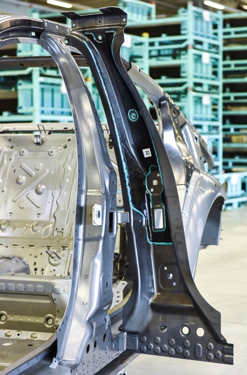
Fig. 2.
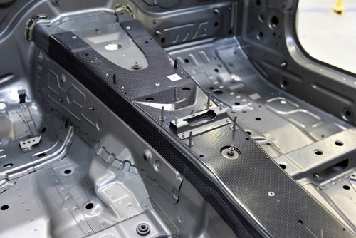
Fig. 3a.
When asked about galvanic corrosion, Ahlers explains that the rear cross member/upper trunk cover (Fig. 4) is the only CFRP part in touch with aluminum. In that case, adhesive is used to isolate the CFRP from the aluminum and there are no through-hole fasteners to act as a corrosion bridge. Also, the aluminum is painted (black) to prevent corrosion from environmental factors. “The key is to have the right materials and to have them support each other,” says Ahlers.

Fig. 3b.

Fig. 4.
The cross member/trunk cover is molded from epoxy sheet molding compound (SMC) reinforced with recycled carbon fiber. The fiber is a lofted material, derived from 7 Series waste as well as waste from cutting dry fabrics for BMW’s i3 and i8 moldings. These leavings are carded and formed into nonwoven mat. “In this process, the knowledge is where to put the resin in and how to press it all to avoid dry areas, which happens if you have too much fiber,” says Ahlers. “But, if you have too little fiber, you have too much resin and not enough mechanical properties.”
The recycled carbon fiber SMC parts are not made by BMW, but instead are delivered from a supplier and use epoxy resin. The type of epoxy used, however, is optimized per process. For example, Hexion’s (Columbus, OH, US) quick-curing EP TRAC 0600/EK TRAC 06130 epoxy is used in the 7 Series’ HP-RTM roof bows and the wet compression molded tunnel.
BMW continues to work closely with its resin suppliers. “We have developed faster resins since the i3 and i8,” Ahlers notes, “and we also did all new testing, starting with coupon testing to feed the simulations and then moving up through components to qualify each material for each part.”
At this point, BMW Group Plant Dingolfing’s head of Press Shop and CFRP Production Peter Wolferseder takes over the tour. As he leads the way into the open production area, he explains that the CFRP Shop’s 100 employees cover three shifts, five days per week. Inside, a bank of 10 automated CNC milling machines supplied by EIMA Maschinenbau, (Frickenhausen, Germany) flanks the left side with a line of presses opposite — five for wet compression molding and two for hybrid B-pillar pressing — all supplied by Dieffenbacher (Eppingen, Germany). Many of the tools in the presses, he says, are supplied by FRIMO (Lotte, Germany). “We have a good relationship with them, and we also build some tools in-house.”
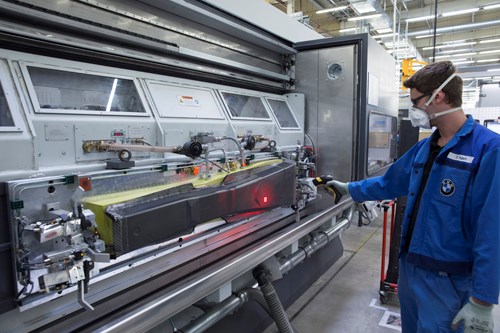
Fig. 5a.
Walking past the CNC milling cells, Wolferseder shows how a wet-compression-molded tunnel part is placed into the front of the machine while another is being milled at the back, for maximum throughput and efficiency (Fig. 5). “No dust escapes,” he points outs. “It is a completely clean environment.”
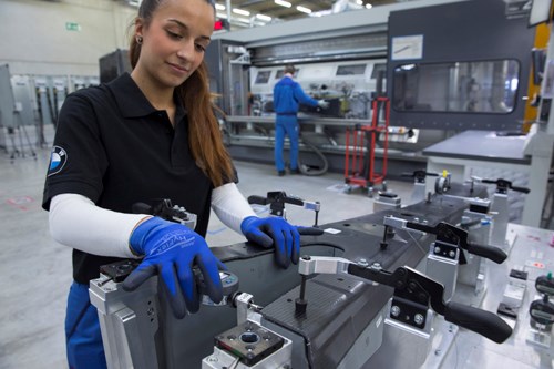
Fig. 5b.
Wet pressing of sills
The sills that run along the lower sides of the BIW are assembled from two CFRP parts, also wet compression molded. A sill manufacturing cell equipped with two KUKA (Augsburg, Germany) robotic arms applies epoxy resin simultaneously to two dry textile preforms. The non-crimp fabric (NCF) for the preforms is made at BMW’s joint venture plant SGL Automotive Carbon Fibers, 60 minutes away in Wackersdorf, which also supplies the i3 and i8 lines. The resin is mixed and injected via a dual-head system supplied by KraussMaffei (Munich, Germany), with an integrated volume flowmeter that records the quantity applied to each stack. The resin forms a pool in the center of the stacks, leaving about an inch or so around the edges. “If the resin goes to the edges, then the needle grippers we use to pick up the preforms would get covered in resin and no longer work,” explains Wolferseder (Figs. 6a and 6b). “The resin application is programmed to fully impregnate to the edges during the pressing.”
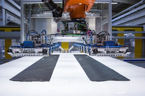
Fig. 6a.
Why two robots instead of one? “Because both preforms should be the same,” Wolferseder responds, “with the resin sitting on them for the same amount of time. If you only had one robot, one preform would have resin sitting for some seconds more than the other. Also, the robots are not very costly, so it is no issue to have two.”
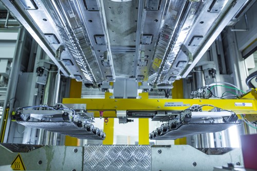
Fig. 6b.
Designed with latency, so cure does not begin until the press cycle, the resin sits for some seconds, penetrating through the preforms vertically. The wet preforms are picked up and placed into the press by the robotically actuated needle grippers. The press then applies pressure according to specified ramp, with the final 10 mm of “daylight” closed very slowly. “Our special recipe to produce these parts is to coordinate the temperature, pressure and resin curve,” says Wolferseder.
Two molded stacks are produced with one stroke (Fig. 6c). “We will cut these in half so that we end up with four parts from one cycle,” says Wolferseder. “We mostly use tools with four cavities to increase the overall output capacity of our machines.”

Fig. 6c.
He points out that this is a completely unattended process and totally reliable. “There are two people at the end to take parts off the line and to do QA checks. If there is a defect, they can address this in the machines,” says Wolferseder. “Wet pressing is not unique,” he adds. “What is unique is this industrialization.”
Hybrid B-pillars
The prepreg used to reinforce the B pillars is delivered from Hexcel Austria (Neumarkt) using epoxy resin from an undisclosed supplier and carbon fiber from SGL Carbon SE (Wiesbaden). It arrives precut to shape and on trays, which are stacked onto trolleys and rolled into the workcell’s feed station. “The solid green layer on top is the epoxy adhesive which will bond the CFRP to the hot-formed steel B-pillar,” says Wolferseder, “but also provide isolation against galvanic corrosion.”
A robot picks up two of the adhesive-coated prepreg preforms and places them on a light table to enable an automated stack orientation check, which is completed in a few seconds by a Vision Machine Technic (Mannheim, Germany) system. The robot then picks up the preforms again and after returning to the workcell’s periphery swivels to the other side of the robot transit aisle and places the preforms into one of several drawers in a convection oven. Here, the CFRP preforms and the steel B-pillars are preheated before pressing. The preforms are then transferred from the heating drawer to a forming station where they are placed onto and shaped by a set of pins that essentially form an articulated tool.. After this is completed, the two shaped preforms are mated to two preheated steel B pillars and then fed into the press. A twin-cavity tool, supplied by Koller Formenbau (Dietfurt, Germany), molds a complete set of left and right B-pillars in one stroke. Wolferseder explains that the presses used here are the same as those employed in wet pressing, but the pre-and post-press equipment is completely different.
After a high-temp, high-pressure cycle, the two finished parts are removed and set on a shelf where they will cool at ambient temperature. “The cooling stage is needed in order for the parts to finish hardening,” says Wolferseder, “and also for the two workers at the end of the line to be able to handle them.” The robot receives a signal that the temperature of the parts is cool enough and then transfers them to the conveyor belt where the workers will pick them up, perform a visual inspection for quality and will also remove the peel ply/foil on top of the prepreg. “The CFRP allows us to use a thinner, more lightweight steel part,” says Wolferseder, “saving 2 kg while providing superior crash performance.”
Dingolfing Body Shop
A short drive from the CFRP Shop is the 40,000m2 Body Shop, where CFRP parts and metal parts from the Press Shop are joined into modules, which then are assembled into the 7 Series BIW. CW’s tour here is led by Christoph Roth, head of production for the BMW 7 Series Body-in-White. Scanning the floor from an overhead viewing bay, the high degree of automation is obvious — 460 robotic arms are used in the shop’s 7 Series section alone, overseen by 130 technicians per shift.
Roth explains that CFRP parts come into this building through an exterior washing area where dust from machining is removed. “All of the parts do this except for the B-pillars because they are not machined and they are also not bonded during BIW production, only welded,” Roth explains. “This washing and then drying is necessary because all of these parts will be bonded, so the surfaces must be very clean.” The CFRP parts are fed into the Body Shop on a just-in-time (JIT) basis, directed from the overall production control system. After drying, the parts are sent to one of the 20 automated production cells that join the CFRP parts to metal. These cells produce parts for all 7 Series derivatives, including left and right hand drives and extra-length version.
“Figuring out how to join all of these parts and the production cells needed was the challenge,” says Roth. “Every joining method already existed somewhere in the automotive industry, but the challenge was how to bring it all together with these new materials and make it all work for our production cycles.” The roof frames and lower sill reinforcements are glued and riveted, but the rivets are used only to hold the glued surfaces in contact until the epoxy adhesive cures. “We decide on what fasteners to use depending on where the part is in the car, the material and also the access,” he explains. “If you can only access one side, then you use flow-drill-screws, for which we have also developed very innovative new technology.” The latter require no pilot hole, feature an undercut beneath the heads and very fast installation, which heats up the surrounding material and, as a result, “welds” the fasteners in to a degree. Roth continues, “We use 150 flow-drill-screws per each 7 Series BIW. If the machine can gain access to top and bottom, then we can use rivets.”
Roth describes one area where fasteners have been eliminated: “The aluminum casted part that is glued to the CF SMC rear support replaces up to 30 separate parts but has now been integrated into a one-piece unit.” Walking past multiple rectangular, fenced-in production cells, each with two or three robotic arms moving parts through various preparation and joining operations, he points out a worker who is performing ultrasonic inspection on a completed subassembly. “Three parts per shift are pulled from each station and tested either nondestructively or with light force to ensure strength,” he says.
Tunnel assembly cell
Trolleys with CFRP and metal parts are loaded into the automated production cell. A Kuka robotic arm picks up a CFRP tunnel and rotates the piece beneath a mix, meter and dispense (MMD) nozzle for application of the epoxy adhesive (Fig. 7). The part is then placed under a set of cameras for a quick QA check of adhesive placement vs. a reference. “There must be no interruptions in the length and it also checks the width of the adhesive bead,” explains Roth. “It doesn’t worry about the thickness because we apply more adhesive than necessary and also use spacers which maintain the distance between the parts for uniform bondline thickness.”
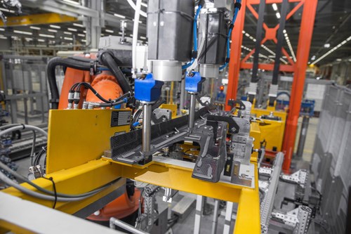
Fig. 7.
“We use roughly 150m of glue per 7 Series BIW,” says Roth. There are drums of adhesive from Sika AG (Baar, Switzerland) and also MMD machines at each production cell. “We have used SIKA and bonding for metal parts for years, says Roth, “but the adhesive we use for the CFRP stations is a specialty adhesive for CFRP-to-sheet-metal bonding.”
The tunnel is then mated to the steel components of this subassembly. Rivets are applied to affix the CFRP and steel pieces together until the epoxy hardens five hours later, when the BIW goes into the paint oven. The tunnel production cell produces 17 units per hour.
When asked about issues encountered while developing the various press cells, Roth responds, “The challenge was how to qualify personnel to repair and maintain these new machines for joining multiple materials. So, we pulled our best maintenance personnel and placed them within the process development group so that they would understand the technology behind these machines and processes.” These personnel then became specialists for the new joining equipment. “It is key that they were involved from the beginning,” Roth adds.
Building the Carbon Core
Other cells that join CFRP and metal parts include those for sills, B- and C-pillars and roof rail assemblies. Most of the completed subassemblies that contain CFRP are used to form the BIW’s mid-section. The C pillar reinforcement and upper trunk cover are on the rear section (Fig. 8). The front section is all metal.
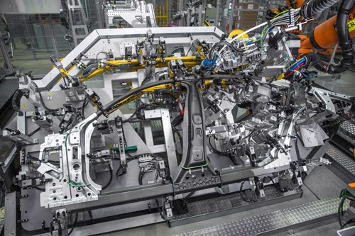
Fig. 8.
Once a subassembly is completed, it is loaded by elevator onto an overhead conveyor that transports it to the BIW assembly line. Assembly of the BIW begins with key steel and aluminum chassis pieces joined and welded atop a moving sled. The BIW then progresses through subsequent stations where additional subassemblies are lowered, robotically placed, fastened and/or welded until the Carbon Core is complete (Fig. 9).
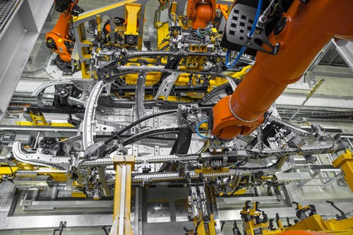
Fig. 9a.
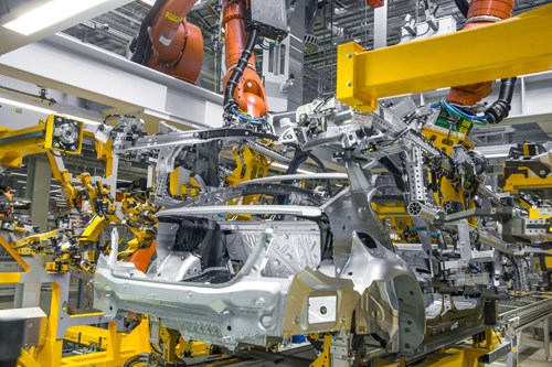
Fig. 9b.
Final assembly line
Completed BIWs are painted before proceeding through Hall 52, which produces 5, 6 and 7 Series vehicles. An adjacent Hall 50 produces BMW 3,4 and 5 Series cars. A car rolls off the line every 83 seconds in Hall 52, and every 58 seconds in Hall 50. Each hall contains 350-400 stations on three levels: Pre-assembly modules are on the ground floor (level 0) and transported up to level 2, where vehicle assembly is completed and then back down to level 1 for the finishing line.
“All of our cars are built to order, so this presents a challenge,” notes CW’s guide for Hall 52, head of assembly at BMW Group Plant Dingolfing Robert Küssel. “There is no other auto manufacturing center that has this much complexity.” Stopping at one position in the line, an instrument panel is fed up from the ground floor through an elevator. This station’s technician walks over and attaches a robot to the completed IP module. He then guides it to a car moving slowly through the line where he places it inside, but the robot does the installation. The whole process is controlled and documented by the equipment. “Parts are sequenced in Logistics in what we call Lineside Supply,” says Küssel, “this builds in a lot of flexibility to our assembly lines. We can easily adapt to new parts and new models.” He notes the whole building is fed by 200 multi-car material supply trains per hour.
On the finishing line, cars are tested again for functionality of each subsystem. Transported to the ground floor, they are driven through a short test track to check noise, vibration and harshness (NVH). A certain number of cars per shift are selected for road testing on a longer test track adjacent to the assembly halls, and a subset of those go out on the highway next to the facility for a longer test. “It’s all about quality,” says Küssel. “Our customers expect a very high level of quality from us.”
CFRP-integrated industrial production
And that is the real story of this plant: Efficiency in manufacturing, yet quality in every detail, despite myriad individually specified components. Carbon parts may be made in their own shop, but they are prepped, joined and painted with all of the other BIW parts into a coherent, well-designed and high-performance platform. CFRP is just another specialty, another complexity, another functionality rolled into what BMW already does so well. It has become standard procedure, but only because the company recognized and addressed challenges early on, in areas as diverse as the carbon fiber supply chain, part processing, isolation from galvanic corrosion, quality control and technician training.
“We use CFRP not just here and there in a visual part to be flashy,” says Küssel, “but in a way that adds functionality and performance to the car.” Articles in the industry press suggest that BMW will extend CFRP use into new Motorrad motorcycle models and an all-electric i5 crossover SUV expected to be revealed next year and in production by 2019. Upon exiting Plant 2.4, and seeing several camouflaged, pre-production vehicles undergoing tests, CW’s question is: “which Dingolfing model will be next?”


.jpg;maxWidth=300;quality=90;format=webp)


Related Content

Cycling forward with bike frame materials and processes
Fine-tuning of conventional materials and processes characterizes today’s CFRP bicycle frame manufacturing, whether in the large factories of Asia or at reshored facilities in North America and Europe. Thermoplastic resins and automated processes are on the horizon, though likely years away from high-volume production levels.
Read More
JEC World 2022, Part 3: Emphasizing emerging markets, thermoplastics and carbon fiber
CW editor-in-chief Jeff Sloan identifies companies exhibiting at JEC World 2022 that are advancing both materials and technologies for the growing AAM, hydrogen, automotive and sustainability markets.
Read More
One-piece, one-shot, 17-meter wing spar for high-rate aircraft manufacture
GKN Aerospace has spent the last five years developing materials strategies and resin transfer molding (RTM) for an aircraft trailing edge wing spar for the Airbus Wing of Tomorrow program.
Read More
Multi-material steel/composite leaf spring targets lightweight, high-volume applications
Rassini International was challenged by Ford Motor Co. to take weight out of the F-150 pickup truck. Rassini responded with a multi-material steel/composite hybrid leaf spring system that can be manufactured at high volumes.
Read MoreRead Next

Composites end markets: Energy (2024)
Composites are used widely in oil/gas, wind and other renewable energy applications. Despite market challenges, growth potential and innovation for composites continue.
Read More
From the CW Archives: The tale of the thermoplastic cryotank
In 2006, guest columnist Bob Hartunian related the story of his efforts two decades prior, while at McDonnell Douglas, to develop a thermoplastic composite crytank for hydrogen storage. He learned a lot of lessons.
Read More
CW’s 2024 Top Shops survey offers new approach to benchmarking
Respondents that complete the survey by April 30, 2024, have the chance to be recognized as an honoree.
Read More