
Inside R and D: A-VaRTM takes flight in Japan
Tests show out-of-autoclave process can reduce costs on new regional jet.
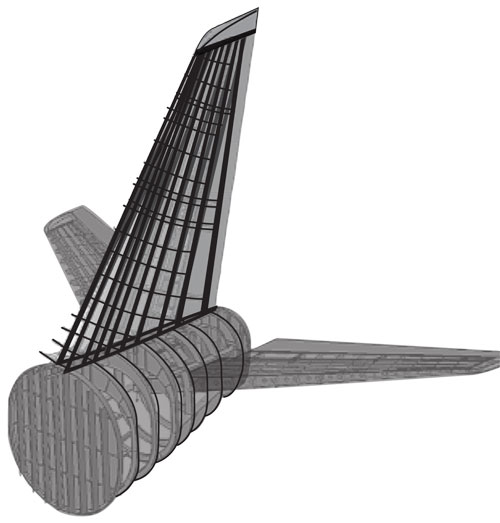
Empennage R&D: MHI engineers are conducting research into a variation of vacuum-assisted resin transfer molding (VARTM), focusing prototyping/testing efforts on the vertical stabilizer.
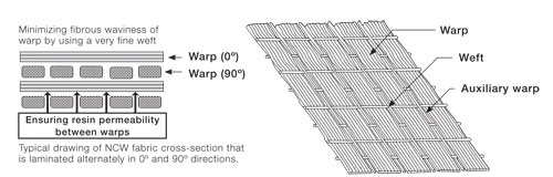
Fabric construction: MHI’s noncrimp woven (NCW) fabric features warp fibers of carbon fiber, interrupted at regular intervals by “auxiliary” warp fibers of fine glass that create resin flow channels. The unidirectional fabric is tied together with fine glass weft fibers.

The Mitsubishi Regional Jet: Artist’s conception of single-aisle, short-haul jet that Mitsubishi Heavy Industries (MHI, Nagoya, Japan) will build in 70- to 90-passenger models. This first commercial passenger plane made in Japan since 1965, it will feature VARTM-processed carbon fiber composites in primary structure. Source: MHI
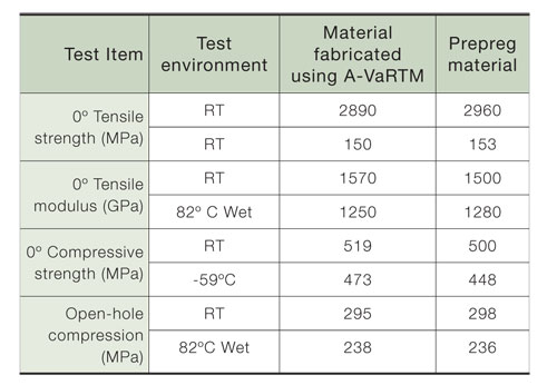
Mechanical property parity: Test results show that in parts made by A-VaRTM, mechanical properties have reached a level comparable to those of autoclaved prepreg parts.
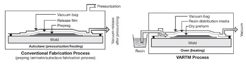
Autoclaved prepreg vs. A-VaRTM: This illustration compares and contrasts the two methods.
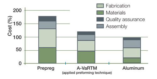
Cost comparison: This graph of the relative costs for three methods of empennage box structure shows that the A-VaRTM process paired with MHI’s preforming technique reduces the cost of a composite component to only 1.2 times that of an aluminum structure.


The much-publicized Mitsubishi Regional Jet (MRJ), a recently launched short-haul 70- to 90-passenger single-aisle aircraft, will be the first commercial passenger aircraft produced and assembled in Japan since the YS-11 turboprop entered service in 1965. Significant R&D funding for the jet initially evolved out of the environment-friendly, high-performance, small-aircraft program begun by Japan’s New Energy and Industrial Technology Development Organization (NEDO, Kanagawa, Japan), with component prototyping and testing conducted by the Japan Aerospace Exploration Agency (JAXA, Tokyo). In March 2008, Tokyo-based Mitsubishi Heavy Industries (MHI) announced it will build the prototype aircraft and production models of the new plane at its Nagoya Aerospace Systems Works, and on April 1, Mitsubishi Aircraft Corp. was formed at that location to conduct MRJ business.
Building on experience
MHI already has showcased its composites expertise as part of The Boeing Co.’s (Seattle, Wash.) international 787 Dreamliner airframe team. (Read more about the Boeing supplier team in "Learn More," at right. See "Boeing sets pace ...." under "Editor's Picks.") Team partners are providing, respectively, the center wingbox, detailed design and assembly of the center wingbox and part of the forward fuselage. Boeing describes this center wingbox (weighing 55,000 lb/24,948 kg in a full-scale test article, including test-only hardware) as a cantilevered beam in three structural parts that carries the load of the wing to the fuselage and supports leading and trailing edge devices, control surfaces, engines and landing gear. In operation, the wingbox provides the lift and fuel-carrying capacity needed for the aircraft. Upper and lower skins, spars and stringers on the wingbox are produced by MHI via automated tape laying (ATL) using Toray’s T800 carbon fiber in toughened epoxy prepreg. Boeing identifies MHI’s one-piece wingbox skin tool as the largest in any factory for the 787. MHI is spending more than $750 million (USD) on R&D and construction of fabrication and assembly factories in Nagoya, including one of the world’s largest autoclaves.


Breaking with tradition
Despite this capital-intensive scale-up for manufacturing the 787 composite wingbox structure, MHI is eschewing its established but costly autoclaved prepreg methods, and researching instead a different course for building some airframe structures on the much smaller MRJ. Seeking to significantly reduce production and maintenance costs as well as total aircraft weight and fuel consumption, MHI says a key technology innovation for this new aircraft will be use of advanced vacuum-assisted resin transfer molding (A-VaRTM). Since 2003, the company has conducted R&D efforts, in concert with Toray, on both preforming and A-VaRTM in the belief that these technologies hold the promise of dramatically optimizing production for the MRJ’s empennage (horizontal and vertical stabilizers and fuselage interface).Conventional resin transfer molding (RTM) uses pressure to push resin into a closed mold. To hold part dimensions, the tooling materials in upper and lower mold sections must be rigid and therefore are typically machined from metal, which makes tooling very expensive, particularly for large parts. A common variation, vacuum-assisted RTM (VARTM), evacuates the closed mold cavity with the negative pressure of vacuum, which draws resin into the mold. This difference permits use of less expensive materials (typically, nylon bagging films and tape) to enclose a one-sided hard tool, with the result that tooling costs can be reduced significantly. In both the RTM and VARTM processes, a dry preform can be used and mold tools and resin can be preheated to reduce resin viscosity and accelerate cure (see sidebar at end of this article).
Advancing beyond VARTM
MHI puts the advanced in its A-VaRTM process through a proprietary method that involves hot compaction of the preform and its treatment with thermoplastic particles. In conventional VARTM, the addition of thermoplastic serves as a tackifier to consolidate the preform and can be added as powder, spray or as MHI does, in particle form. Notably, the use of thermoplastic particles within the preform also permits the use of a lower-viscosity and less-expensive epoxy thermoset resin during infusion. The tackifier and resin intermix when heated during cure, with the result that the epoxy exhibits, in the final composite, the durability and impact resistance typically associated with a preformulated toughened epoxy. Though the details of MHI’s compaction timing, temperature and exact thermoplastic selected are proprietary, the way these process elements are controlled stabilizes the preform against slippage, enhances handleability and conformance of the preform to the mold surface, and ultimately improves interlaminar properties in the finished part. Further, these preforms can be multistacked to create a uniform and straight cross-section and to lay the foundation for automated production.Likewise, MHI uses a proprietary diffusion or flow media to control the resin infusion flow and rate, as well as to bleed off excess resin. This maximizes fiber volume in the finished composite part; for aircraft primary structure, MHI has targeted fiber volume of 55 to 60 percent. MHI’s research has shown that the hot compaction and select diffusion media improve resin flow in the vertical or through-the-thickness direction and might provide some z-directional, out-of-plane strength benefits as well. Oven cure occurs in two steps: first, cure under vacuum and then postcure in an oven at 350°F/180°C.
Fabricating the fiber form
Essential to the performance of finished parts and to optimization of MHI’s resin infusion process is a specially designed, noncrimp woven (NCW) fabric preform. The NCW features Toray’s intermediate modulus (24K) T800SC carbon fiber bundles as the primary structural element, making up the majority of the 0° or warp fibers. Very fine glass fibers, denoted by MHI as “auxiliary warp” fibers, are grouped in such a way that they create resin infusion paths or channels along the 0° axis between themselves and the larger warp fibers to facilitate flow during A-VaRTM. Finally, very fine glass fibers are used in the weft or 90° direction of the preform to tie warp and auxiliary warp fibers together (see diagram, at right). Preforms are created by stacking the NCWs. As noted in the diagram, the stacking sequence alternates the NCW fabric on the 0°/90° axes, giving the preform the stability and processability typically obtained with a conventional woven fabric, but because the construction does not crimp the carbon fibers, it does not compromise the tensile strength or elastic modulus of the fibers. Further, the stacked NCWs can drape individually during preform manufacture.In its 2005 research, MHI constructed I-shaped stringers from the NCW preform and TR-A36, a low-viscosity, two-part epoxy that cures at 350°F/180°C, also developed by Toray. The preform exhibited superior drapeability, compared to prepreg, formed a continuous cross-section in the stringers, and avoided excessive thickness change rates at the corners and web surfaces. In its cost comparison at that time, MHI predicted that the cost of a composite component could be reduced to only 1.2 times that of an aluminum structure (see chart, at right).
Mechanical properties reported by MHI for the NCW fabric infused with TR-A36 resin at room temperature are charted at right. MHI concluded that competitive mechanical properties are realized with the preform and two-part epoxy as compared to carbon fiber/epoxy prepreg T800S/3900-2B for primary aircraft structures.
Testing preformed prototypes
In 2007, MHI updated the progress of its A-VaRTM R&D for primary aircraft structure at the Japan SAMPE Symposium and Exhibition in Tokyo. Research targets for materials/processing of structure such as the MRJ vertical tail included a 20 percent weight reduction and 30 percent total cost reduction compared to a conventional aluminum alloy structure. Additional test articles have been prototyped, including C-shaped spars, T-shaped spars and stringer/skin sections.
MHI’s first full-scale, proof-of-concept vertical stabilizer has been constructed and measures 18-ft tall, 4-ft wide and 16-inches thick (5,500 mm by 1,200 mm by 400 mm). The component incorporates ribs, spars and skin panels that have 0.24-inch/6-mm maximum thickness. Stringers are cobonded with the precured skin panel, using a film adhesive, and the assembled component is subsequently postcured in an oven more than 19.7-ft/6m long.
The most promising result of this work concerns fabrication cycle time estimates: MHI achieved an 80 percent reduction in fabrication time of stringers on the panels (seven stringers cobonded per panel) compared to conventional aluminum alloy boxes. As a result, the company concluded that the recurring production cost for an A-VaRTM’d vertical stabilizer box will be almost the same as that for a conventional aluminum alloy box.
Improving on initial success
Since then, MHI has built a second full-scale vertical stabilizer box for static strength testing. The process for this part demonstrated improvements in hot compaction and, therefore, produced preforms of greater density. MHI reports that this box structural element incorporated fuselage interfaces and more accurately represented the actual MRJ concept design. A static test rig also was constructed, and the test specimen — again, a cobonded panel of skins and stringers, plus the spars and ribs — was assembled with mechanical fasteners. For this test article, particular attention was paid to the quality of thickness transitions in ply drop-off areas. MHI was seeking to avoid wrinkles that can occur with prepreg in three-dimensional geometry with ply drop-offs. The OEM observes that dry preforms have been easier to fit around 3-D geometry, thereby reducing the potential for wrinkles.Strength tests of the second vertical stabilizer box were conducted at JAXA’s Chofu Aerospace Center Aerodrome Branch (Tokyo), based on performance parameters set for the MRJ.
(JAXA is a national partner in research efforts focused on elemental technologies that could improve Japan’s passenger aircraft. In that role, JAXA has conducted its own prototyping work on primary aircraft structure, using conventional VARTM, including a 6.9-ft/2.1m span wingbox test panel and a full-scale 19.7-ft/6m wingbox.)
MHI’s composite stabilizer box was subjected to maximum bending and shear force strains, measured by strain gauges attached to the skin, stringers, spars and ribs. Displacements were measured by gauges on the spars. Maximum load was applied to the box in 5 to 20 percent increments. No detrimental, permanent deformation occurred as a result of this testing. When compared with finite element model (FEM) analysis, using classic lamination theory, the strain distribution results were within 5 percent of the FEM results.
After the static strength tests, MHI cut 35 specimens from the different skin areas of the full-scale box test article and performed static compression tests on them. Although MHI was concerned that the tests could reveal problematic fiber volume variations or wrinkles in thick areas, performance proved to be acceptable; the observed variation was only 2 percent, and degradation was nominal across the 16- to 52-ply thicknesses. No significant variation was detected in the test article’s elastic modulus during this round of tests.
In 2008, MHI continued its R&D efforts to move the preforming method and the A-VaRTM process to maturity, working toward the 30 percent total-cost reduction target. Material characterization has recently begun, and discussions are underway with Japan’s Civil Aviation Bureau (JCAB) to determine the full range of tests and inspections that will be required to verify that strength, fatigue resistance and other critical performance properties of parts fabricated by A-VaRTM will meet aircraft standards. This data will be essential for obtaining a type certificate for the MRJ.
Awaiting the future
Expectations are high for the MRJ. Slated for first flight in 2011, after eight years in development, the plane represents the fulfillment of Japan’s longed-for reentry into the commercial aircraft market. Equally important, the MRJ’s empennage structure could be the fruition of composites industry efforts to develop faster, less-expensive processing alternatives that can yield autoclave-quality primary aircraft structure without the autoclave.To access MHI’s most recent MRJ-related R&D report, entitled “Development of Advanced Vacuum-assisted Resin Transfer Molding Technology for Use in an MRJ Empennage Box Structure,” see the latest Mitsubishi Heavy Industries Technical Review, Vol. 45, No. 4, December 2008, atwww.mhi.co.jp/technology/review/pdf/e454/e454001.pdf.


.jpg;maxWidth=300;quality=90;format=webp)


Related Content

Materials & Processes: Fabrication methods
There are numerous methods for fabricating composite components. Selection of a method for a particular part, therefore, will depend on the materials, the part design and end-use or application. Here's a guide to selection.
Read More
From the CW Archives: Airbus A400M cargo door
The inaugural CW From the Archives revisits Sara Black’s 2007 story on out-of-autoclave infusion used to fabricate the massive composite upper cargo door for the Airbus A400M military airlifter.
Read More
Demonstrating functionalized, cost-effective composites using additive extrusion
Hybrid thermoset/thermoplastic composite part with 3D-printed functionalization demonstrates technology possibilities and EmpowerAX open platform offering expertise from members throughout the process chain.
Read More
Engine vane demonstrates potential for gapped, unidirectional dry fiber for infusion
GKN Aerospace and its partners developed an aircraft demonstrator component made with TeXtreme’s latest Gapped UD material, proving out a dry, infusible tape meant to compare in performance to UD prepreg.
Read MoreRead Next

Inside Analysis: Simulating VARTM for better infusion
A resin flow simulation tool is helping to optimize liquid molding of aerospace parts.
Read More
A400M cargo door: Out of the autoclave
This structural military airframe part is the largest made to date via the vacuum-assisted resin infusion process.
Read More
Autoclave Quality Outside The Autoclave?
Pioneers of out-of-autoclave processing in aerospace applications answer a qualified but enthusiastic Yes!
Read More