Inside Manufacturing: An autoclave for the 787 center wing box
Development partners overcome cultural and geographical challenges to ensure cure of this massive composite structure for Boeing's Dreamliner.
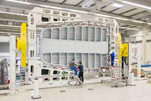
On May 26, 2005, The Boeing Co. awarded the production contract for its 787 Dreamliner’s all-composite center wing box, the critical structure that joins the wings to the fuselage, to Fuji Heavy Industries (FHI, Nagoya, Japan). Long before the ink was dry on the contract, however, the long-standing Boeing development partner (also the manufacturer of Subaru automobiles) had begun construction of a 1 million-ft2 (more than 92,900m2) facility to manufacture the 17.4 ft long (fore to aft) by 19 ft wide by 4 ft thick (5.3m by 5.8m by 1.2m) structure. Work on the largest piece of equipment in the new plant, the roughly 23-ft long by 23-ft diameter (7m by 7m) autoclave required to cure the center wing box, had begun almost a year earlier and halfway around the world at U.S.- based equipment manufacturer Taricco Corp. (Long Beach, Calif.).
The project was unusual for Taricco Corp. not only because the autoclave is the company’s largest — and one of the largest ever built — but also because, for the first time in its history, the company did not have full project responsibility. Tasked with designing the autoclave and supplying the materials, Taricco Corp. was permitted only a technical supervisory role during autoclave construction and installation at the Fuji plant. The limitation was necessitated by several practical impediments. First, the autoclave’s pressure vessel was so large that, had the company constructed it in California and shipped it to Japan, government regulations would have prohibited its transport on Japanese roadways. Second, although Taricco Corp. is ASME-approved in the U.S. for the type of welding required for autoclave construction, the company is not certified to equivalent JIS standards in Japan. The bulk of the work, therefore, would be done onsite by one of what turned out to be three project partners. In Japan, explains Taricco project manager Dr. Patrick Payton, large projects are typically awarded to one large manufacturer, but custom dictates that project tasks are divided among members of that company’s keiretsu (horizontally and vertically integrated alliances). For its keiretsu, Fuji Heavy Industries hired Mitsubishi Technos Corp. (MTC, Tokyo, Japan) to act as project manager for the design and installation of the autoclave. For the actual build, however, MTC turned to Shinko Engineering and Maintenance Co. Ltd. (div. of Kobe Steel, Kobe, Japan), whose welding-accredited autoclave fabrication team, Payton notes, includes Japan’s national welding champion.
Stateside preparations
By July 2004, Taricco Corp. had completed the preliminary scope of work and initial drawings for the autoclave — Payton notes that company founder and president Tari Taricco designs each autoclave personally — and his team had already spent months working out the design details. One of the greatest challenges, even in the design stage, was project coordination. “For this project, we had to have all of our drawings ahead of time so that we could discuss them with the Japanese team of fabricators and project managers,” Payton says. “But there were times when we could not complete our drawings because the Japanese team was still trying to detail its specifications.”
A case in point involved the 20-ton, electric-powered Automatic Guided Vehicle (AGV), which would be used to transport the wing box tool and layup into the autoclave. Payton’s team had to design the AGV tracks in the autoclave interior to accommodate the AGV wheelbase and ensure that the ramp on which the AGV would enter and exit the autoclave chamber could handle individual wheel loads. “The Japanese customer and its team were still finalizing how many wheels the AGV would have and how far apart these wheels would be, while we were expected to have our autoclave interior drawings completed,” says Payton. “This is not a small machine nor a trivial part of the design.” Ultimately, some design features had to be delayed well into the manufacturing process. “We actually proceeded through hydrotest of the autoclave shell before we had a final design for the interior,” Payton notes.
When the pressure vessel design was complete, 1.25-inch/31.75-mm thick steel plates were cut to size and shipped to Japan where they were rolled into half cylinders and assembled to create the pressure vessel’s cylindrical shell. Steel plate also was shipped to Japan for the vessel’s dome-shaped ends, called “heads,” one for permanent attachment to the assembled vessel and the other to form its massive entry door. A Japanese sub-contractor press-formed this steel plate into the heads, which were then cut in half and shipped to the job site. Taricco Corp. fabricated, then halved, two steel saddles (U-shaped fixtures that cradle the vessel cylinder) and doubler plates, which form the cylinder/saddle interface to distribute the mass of the cylinder and avoid point-compression loads on the vessel body.
Taricco technicians also produced the three 23-ft/7m diameter steel rings that would form the head flange, the shell flange and the locking ring for the pressure vessel door closure mechanism. Each ring was forged in one piece, machined to the final configuration (a tolerance of 25 to 30 mils) and then cut in half for shipping. To ensure that the flange halves would be successfully reunited in Japan, each flange ring was beveled with landings that have tapered ends so the whole mating zone could be filled with weld. This would ensure structural integrity during operation when the head flange and shell flange would be mated to seal the pressure vessel. The locking ring, which encases the mated flanges, would remain a two-piece structure, which would be bolted together during curing operations to ensure the closure’s pressure seal.
Halfway around the world
Payton and his team followed the shipped materials and assemblies, arriving in January 2005 to work onsite with all three Japanese companies. They reviewed every design aspect and monitored each installation step to ensure success. “We had planned for the project to take approximately 10 months, which would have taken us to October of 2005,” Payton relates. “However, due to design requirement changes, the autoclave was completed in early May of 2006.”
“Simply forming a schedule was extremely difficult because the autoclave was being built at the same time as the production facility to house it,” Payton explains, recalling that “when we arrived at the job site, there was no building, no foundation, just steel lying in a field of snow.” A 1.6-ft/0.5m thick concrete pad was poured for the autoclave to sit on until the building foundation was completed and the autoclave assembly could be moved inside and located in its final position.
On the temporary foundation, Shinko welded together two of the half cylinders to make a “can,” using a massive set of heavy power rollers (see Step 1, p. 46) to rotate the can 180° so that the opposite joint could be welded. This operation was repeated for the other two half cylinders. Then the cans were assembled on the rollers and, precisely aligned in a butt joint, the two sections were welded together as they were rotated 360°. Next, Shinko welded the head halves back together to form the front and rear heads and welded the saddle structures (Steps 2 & 3).
The assembly process was complicated by the fact that if such large, heavy parts are simply assembled in an upright position and welded together, the vessel cylinder, flanges and heads would tend to sag under their own weight. Each would be slightly out-of-round and, therefore, would not mate properly. The solution was to follow standard Taricco practice, based on extensive experience with large metal parts: Intentionally weld the rings out of round so that when installed, gravity, acting on the rings’ large mass, would pull them back into round. Long metal posts were spot-welded in place to maintain the oblong shape as the ring halves were mated and welded. This whole process was very foreign and untested to the onsite fabricators, until they saw that it would, indeed, correct for sag. When all welds were complete, each was X-ray inspected.
A crane hoisted the rear head and aligned it with the rear opening of the cylinder, where it was dogged into place. (“Dogging” is the process of welding brackets onto the shell and the head and then using wedges to align the weld bevels on both parts. The weld bevels are butted together all the way around the 25-ft/7.6m diameter cylinder and then welded. The welds between the shell and head must penetrate the full thickness of the 1.25-inch/31.2-mm steel down to a 0.125-inch/3.18-mm landing.)
At this point, the cylinder was craned into place on the saddles. Shinko also drilled through-penetrations and welded on steel couplings at all points where wiring and piping must enter or exit the autoclave chamber; after the vessel is pressure-tested, no further welds are permitted. The cylinder, with the rear head attached, was ready to receive the front head and door closure mechanism. Taricco supervised while Shinko clamped a mating plate, or joint plate, onto each of the locking ring halves and then drilled and tapped holes into each plate so they could be bolted on in the correct position over the head and shell flanges. The head flange and front head were welded together and set aside. Next, the locking ring was placed around the shell flange, and the whole assembly was lifted by crane, located against the front of the autoclave and dogged into place all the way around while the locking ring remained “loose.” The shell flange then was welded onto the cylinder. Finally, a gasket was fixed to the head flange and a crane picked up the head assembly and placed it inside the locking ring, which was rotated to lock the head into place using six hydraulic cylinders.
Hydrotesting and installation
At this point, the autoclave was ready for pressure testing to 1.25 times its maximum operating pressure, the safety factor required by ASME to ensure it can withstand design loads. For safety’s sake, testing is done with water rather than air. Water is incompressible, enabling it to build pressure quickly without storing energy. Pneumatic testing could produce an explosion if highly compressed air were to release its stored energy even through a minor crack.
All through-penetrations were plugged with steel pipe plugs and the autoclave was completely filled with 135,000 gal (1.12 million lb) of water using a small, high-pressure water pump. The internal pressure was actually raised to 1.33 times the designed operating pressure of the autoclave, as specified by JIS requirements, with the hydrostatic pressure equal in all directions. Calibrated gauges on the pump were witnessed and certified by a nationally accredited inspector.
Afterward, the autoclave was drained and prepared for the move to its permanent home in a sunken chamber in FHI’s now-completed composite wing box assembly facility. Large steel beams in a variety of sizes were drilled and bolted together to provide structural support during transport. The bolstered autoclave was then placed on “tanks” — basically, very large roller skates — that enable it to be pulled into its pit using a come-along.
The pit was measured for precise alignment of the autoclave. A line was drawn on the pit floor marking the horizontal axis of the autoclave, which was aligned with the horizontal axis of the pit. At the front of the pit, a second line was then measured at a precise 90° angle (within several seconds of arc) to the first line. This second line would locate the track system for the autoclave’s wheeled door carriage, which had to be aligned at exactly a 90° angle to the autoclave axis or the locking ring wouldn’t function properly.
The door carriage is designed to accomplish two tasks: (1) hydraulically move the front head/door closure in and out so that it can seal and unseal the doorway and (2) transport the extreme weight of the front head to the left (facing head on) until it is clear of the vessel opening. A gear motor reduces the speed to 1 rpm and rotates a chain drive that turns the carriage wheels, moving the front head/door along a railway in the pit floor. A bridge in front of the autoclave was installed to span the gap in the pit for this railway, enabling the AGV to cross from the shop floor into the autoclave interior. The bridge and the autoclave door were designed to move in sync, the bridge moving into place as the autoclave door opens and moving out of the way when the autoclave door is closed. There is only a 0.125-inch/3.2-mm clearance between the AGV tracks on this bridge and those within the autoclave.
Atmospheric control systems
At this juncture, Shinko began to outfit the autoclave’s interior. Technicians welded the heads of small steel pins to the inside of the autoclave’s shell. Sheets of very dense, 3-inch/76-mm thick mineral wool were pushed onto the pins; stainless steel washers were placed over the pins, which were then bent over the washers to anchor the insulation in place. Next, a final layer of sheet steel
with aluminum cladding was clamped onto the autoclave interior to cover the insulation. Clamping was achieved by attaching a 2-inch/51-mm-wide metal strip to a ring of the welded steel pins, approximately every 3 ft/0.91m throughout the autoclave. The sheets of aluminum-clad steel then were laid out, overlapping each edge of the band by about 0.5 inch/12.7 mm but leaving a 1-inch/25.4-mm gap. Another metal strap was screwed on top, allowing the sheets to sheath the interior yet expand and contract during heating and cooling without buckling. Using the preinstalled pass-throughs, Shinko technicians then installed wiring for lighting and instrumentation.
The autoclave’s gas-fired furnace — located in its own chamber within the pit — supplies hot air for the autoclave’s internally mounted heating coil, which heats the vessel’s pressurized atmosphere. The coil consists of two 3-ft/0.91m diameter stainless steel tubes, spaced roughly 15 ft/4.57m apart and connected by a network of smaller tubes, all heliarcwelded into a complex circulatory system. Next, the fan motor was installed into a capsule on the rear of the autoclave. The shaft from the fan motor enters the autoclave chamber through a small nozzle in the rear wall (the nozzle requires no pressure seal because the fan motor chamber is part of the pressure vessel). Inside the autoclave, the 7-ft/2.13m diameter fan was bolted onto the shaft. Then the steel structure that supports the floors, sides and walkways was added, including a structure in the floor to handle the combined loads imposed by the AGV and the 787’s wing box assembly and tooling — the part and tool alone weigh approximately 20 metric tonnes (more than 44,000 lb).
The airflow in this autoclave departed from standard autoclave design. The latter would feature a single annular (ring-shaped) duct, which would propel air through the autoclave along its horizontal axis. When curing a part in an autoclave, the goal is uniformity of temperature across the part as it is carefully ramped up, stabilized and ramped down from cure temperature. Because of the size and shape of the wing box, both axial and vertical airflow would be required. This was achieved by designing a number of ducts into the ceiling and floor so that air flow could be managed via computer-controlled louvers in the ducts, which are adjusted based on the temperature profile measured across the part while it cures.
Air flow in the autoclave would be controlled further by installing a cone-shaped wall in front of the fan followed by a cooling coil. Thus, air will be drawn into the central intake of the fan, which will then push it out radially toward the rear of the autoclave, past the heating coil and then into the floor and ceiling ducts, which will carry the air forward. The air will exit the ducting at the front of the autoclave and then will return back down the chamber, where it is forced past the cooling coil and then funneled by the cone-shaped wall back into the fan to be recirculated. Thus, all of the air in the autoclave will flow across both the cooling coil and heating coil all of the time, which optimizes heating and cooling efficiency. In operation, the cooling coil is shut off when only heating is desired, and both coils are managed by the control system to regulate the temperature inside the autoclave.
Vacuum/pressure systems & process controls
Finally, the vacuum/pressure and control system was installed. Two skid-mounted vacuum pumps were fixed onto a platform to the left side of the autoclave and attached to more than 100 water-cooled vacuum valves, each with its own resin trap, and wired out to programmable logic controllers (PLCs). A subsystem for vaporizing liquid nitrogen and supplying the gaseous nitrogen into the autoclave was installed outside the pit. This enabled a new feature offered by Taricco: the ability to pressurize using air, nitrogen or a customized combination, which can be introduced and maintained to within 3 percent accuracy using Taricco’s autoclave control system.
The Taricco TCS thermal control system is a self-contained package comprised of two Windows-based PCs (one is a redundant system for back-up), common name-brand PLC hardware components, and thermal control system software. (Standard components are used to avoid costly and hard to locate replacements during repair or maintenance.) The PC, with its patented TCS software, acts as the operator interface and runs what is termed the cure cycle “recipe” program, which sends a series of set points to the PLCs via an Ethernet connection. The PLCs then direct all other equipment, including vacuum valves, combustion system, heating coil, cooling coil and fan, to achieve the set points. The TCS software provides extensive data recording, recipe management and archival and network support, and it runs on any version of Windows, says Payton, adding that TCS can support multiple languages and is adaptable to any composite processing hardware, including not only autoclaves and ovens, but presses and resin transfer molding (RTM) equipment as well.
This control system, which is managed from a control center mounted above the pit to the left, enables an operator to control vacuum pressure in the bag during processing from full vacuum up to the pressure inside the autoclave. When a vacuum-bagged part is placed inside the autoclave, the operator can clamp the part against the tool using atmospheric pressure by evacuating the vacuum bag. The operator then can control the differential pressure by pumping air into the bag, selecting any pressure desired up to and including the autoclave pressure, which for this autoclave will be more than 100 psi/6.9 bar.
The control system also manages the temperature not only of the atmosphere inside the autoclave, but also of the part itself. The 787 wing box is large enough that exotherm of the prepreg material during cure is a real concern. Exotherm is caused by an internal chemical reaction in the resin that is set off when a critical temperature is reached. Thus, measures had to be taken to ensure that the part could be ramped slowly enough to keep exotherm in check. Thermocouples placed across the part send temperature data to the TCS computer, which continuously monitors the data for any increase outside of the “recipe” parameters. If it detects an inappropriate temperature rise, it will direct the PLCs that control the heating, cooling and ducting systems to respond in concert to keep the temperature in check and prevent “runaway” exotherm at any point in the part.
After all systems were in place and operational, the vacuum system was checked for leaks, using the same procedure that will be used each time a part is cured. First, the operator pulls full vacuum, and then hoses are connected to the vacuum valves, which are then sequentially opened. Sensors connected to the bag indicate whether or not the bag is holding full vacuum, at which point leaks can be pinpointed and fixed. In normal operation, the operator also tests the thermocouples and then closes the door and initiates the cure cycle.
FAA-certified and ready for production
Completed in June 2006, FHI’s autoclave is already in use, capable of 139 psi/9.6 bar pressure and temperatures up to 400°F/204°C during the eight-to nine-hour cure cycle. The wing box manufacturing facility began making test panels in May 2006, and FHI succeeded in qualifying the facility to FAA requirements for production of 787 wing box assemblies in September. Since then, it has completed construction of several full-scale wing box assemblies as part of the 787’s validation and FAA-certification process. When the part enters production, cured center wing boxes will be transported to an adjacent plant, half as big as the wing box facility, where they will be joined to the 787’s main landing gear well (produced by another 787 partner, Kawasaki Heavy Industries). From there, the assembly will be barged across Nagoya’s seaport bay to the city’s new Centair airport, where it will be airlifted via a modified 747 to Boeing’s Everett assembly plant near Seattle, Wash.
Related Content
From the CW Archives: Airbus A400M cargo door
The inaugural CW From the Archives revisits Sara Black’s 2007 story on out-of-autoclave infusion used to fabricate the massive composite upper cargo door for the Airbus A400M military airlifter.
Read MorePlant tour: Albany Engineered Composites, Rochester, N.H., U.S.
Efficient, high-quality, well-controlled composites manufacturing at volume is the mantra for this 3D weaving specialist.
Read MoreMFFD thermoplastic floor beams — OOA consolidation for next-gen TPC aerostructures
GKN Fokker and Mikrosam develop AFP for the Multifunctional Fuselage Demonstrator’s floor beams and OOA consolidation of 6-meter spars for TPC rudders, elevators and tails.
Read MoreMaterials & Processes: Resin matrices for composites
The matrix binds the fiber reinforcement, gives the composite component its shape and determines its surface quality. A composite matrix may be a polymer, ceramic, metal or carbon. Here’s a guide to selection.
Read MoreRead Next
CW’s 2024 Top Shops survey offers new approach to benchmarking
Respondents that complete the survey by April 30, 2024, have the chance to be recognized as an honoree.
Read MoreFrom the CW Archives: The tale of the thermoplastic cryotank
In 2006, guest columnist Bob Hartunian related the story of his efforts two decades prior, while at McDonnell Douglas, to develop a thermoplastic composite crytank for hydrogen storage. He learned a lot of lessons.
Read MoreComposites end markets: Energy (2024)
Composites are used widely in oil/gas, wind and other renewable energy applications. Despite market challenges, growth potential and innovation for composites continue.
Read More












.jpg;maxWidth=300;quality=90)
