


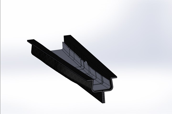
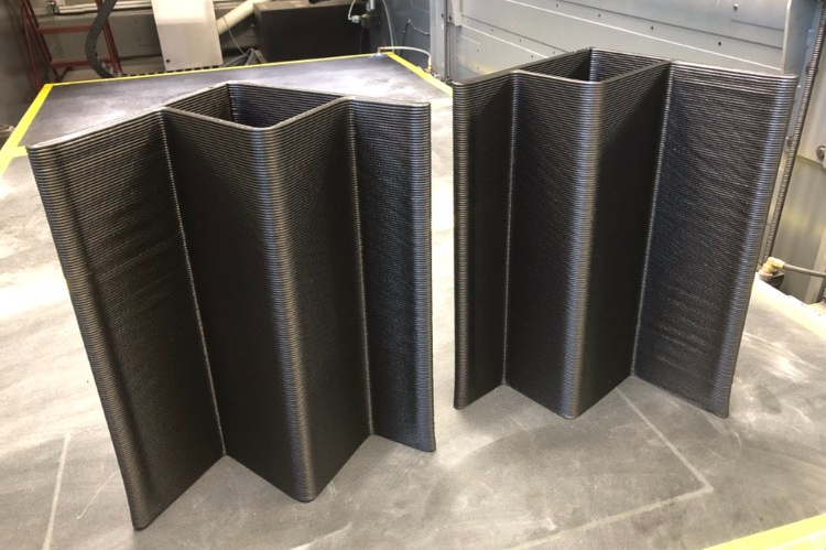
Full-scale C-spar tool design developed at UDRI and representing a section of a larger spar made by Airbus, a section of which was used in the IACMI project. Photo Credit: University of Dayton Research Institute.
For more than three decades, commercial aviation has increasingly embraced composite materials. In fact, more than half of critical structural components on several models of major commercial aircraft today are composites. As use of these materials has grown in terms of both volume and size of parts, it has become increasingly difficult to build tools — particularly affordable tools — to more rapidly prototype and manufacture these parts. For example, wings on the A350 XWB from Airbus SE (Leiden, Netherlands) are each 32 meters long by 6 meters wide and represent some of the largest composite aviation structures ever produced.
"There are now such breakthrough manufacturing technologies on the market that we can expect big steps in tooling evolution, helping us meet the challenges that we are facing in the development of composite aircraft components,” notes M. Pilar Muñoz Lopez, composite manufacturing engineer at Airbus’ Illescas, Spain, plant. “It is crucial for us to investigate these technologies, capabilities and limitations so we can be prepared for the future.”


Given that tooling represents a significant proportion of total program costs for aerostructure parts, and given the increasing size of those parts, new tooling options with lower costs and lead times are needed. An interesting study on hybrid, large-format, additively manufactured (LFAM) tooling for prototype and low-volume production aerostructure parts was recently completed by Airbus, Northrop Grumman Aeronautics Systems – Aerospace Structures Business Unit (Clearfield, Utah, U.S.) and the University of Dayton Research Institute (UDRI, Dayton, Ohio, U.S.) with encouraging results.
Taming thermal-expansion issues
A majority of carbon fiber-reinforced plastic (CFRP) aerostructures are produced from epoxy matrix prepreg. To mold such parts, tooling must survive oven or autoclave cure temperatures up to 180°C/356°F. Also, given CFRP’s very low coefficient of (linear) thermal expansion (CLTE or CTE), it’s critical to match — as closely as possible — tool and molding material CLTEs at room and elevated temperatures. This ensures molds maintain dimensions so that resulting parts also meet dimensional requirements. To avoid distortion or stress in the final structures, it is also important to avoid using a tooling material that cools faster than the part material. As a consequence, the most common tools used to mold large CFRP aerostructures are made from either CFRP itself or Invar, a ferrous alloy of nickel and iron known for its low CLTE. Both are costly and can have significant lead times. Additionally, Invar is difficult and time-intensive to machine and heavy to ship. While steel or aluminum tools can reduce costs, their relatively higher CLTE values limit usage in many applications — particularly when molding large or long parts.
Goals for the project were simple: find a less costly and faster method for making large tools for aerostructures.
Many public- and private-sector studies have evaluated additively manufactured tools printed in thermoplastic materials and concluded they potentially offer benefits including lower costs and shorter lead times to produce thermoset laminate composites. Unfortunately, polymer-based LFAM tooling has issues such as tool porosity, which can lead to significant vacuum loss at cure temperatures/pressures. Resolving this requires additional tool filling rework and surface coatings. An even bigger challenge is highly anisotropic CLTE values, owing to in-plane feedstock filler alignment during extrusion/printing, which can lead to expansion/contraction differences 5-10 times greater in the Z-axis than in the X and Y printing axes. That makes it a challenge to obtain dimensionally accurate parts repeatably and reproducibly — especially when parts are large, have a high aspect ratio and/or feature complex surfaces.
“Everyone interested in additive tooling has been running up against the same issues of porosity and uncontrolled thermal expansion with few effective ways to address those issues,” explains Scott Huelskamp, UDRI team leader, advanced manufacturing process development, Structural Materials Division. “There are lots of people who want to use AM tools, but they’re waiting for someone to solve these problems.”
Given AM’s potential for reducing tooling cost and lead times, the industry has focused considerable effort on addressing expansion issues by exploring new printable materials, printer hardware modifications and innovative modeling approaches. For example, some groups have developed a “compensation value” for designing AM tools to address CLTE differentials. However, Huelskamp notes that determining which compensation value to use is difficult and prone to error. Also, such approaches have been ineffective for female-cavity tools, and tools with trapping features down their length that create die-lock conditions capable of damaging parts during thermal cycling in the tool.
“There’s no compensation factor that’s going to fix that kind of problem,” he adds. “To date, no AM tooling study has fully addressed the need for low, isotropic CTE values at elevated temperature. Without this trait, tool sizes and geometries will always be limited, and larger tools will suffer from higher dimensional errors at cure temperatures.”
In an effort to try new approaches for solving LFAM tooling challenges, an 18-month project was undertaken by several member companies under the auspices of the Institute for Advanced Composites Manufacturing Innovation (IACMI, Knoxville, Tenn., U.S.) and supported by the U.S. Department of Energy and JobsOhio (Columbus, Ohio). The team was led by UDRI and included Airbus and Northrop Grumman. These organizations had previously collaborated on other research, both within and outside IACMI, and thus were familiar with each other’s capabilities.
“Brute-force” approach
UDRI already had considerable experience working on AM tooling studies and is an active member of America Makes (Youngstown, Ohio, U.S.), the U.S. AM consortium. Additionally, the institute had done research for the U.S. Air Force involving AM structures with metallic backings, and has worked with Cincinnati Inc. (Harrison, Ohio, U.S.), producer of Big Area Additive Manufacturing (BAAM) printers, on pure AM tooling.
“We’d also been working with custom compounders on new feedstocks for 3D printers, but nothing we were doing seemed to be making much headway, and we weren’t aware of anyone else having anymore success than we were,” Huelskamp recalls. “That’s when we had the idea to approach the problem differently. If we couldn’t change the way AM materials behaved or predict that behavior directly, then perhaps we could force them to behave the way we wanted indirectly.” Taking what Huelskamp calls a “brute-force” approach, UDRI proposed a hybrid LFAM study that would produce aerostructure tooling by applying conventional CFRP face skins to thermoplastic-composite AM cores.
Goals for the project were simple: find a less costly and faster method for making large tools for aerostructures. The team sought an option that reduced costs 50% and produced at least 10 acceptable prototype or low-volume production parts for subsequent testing

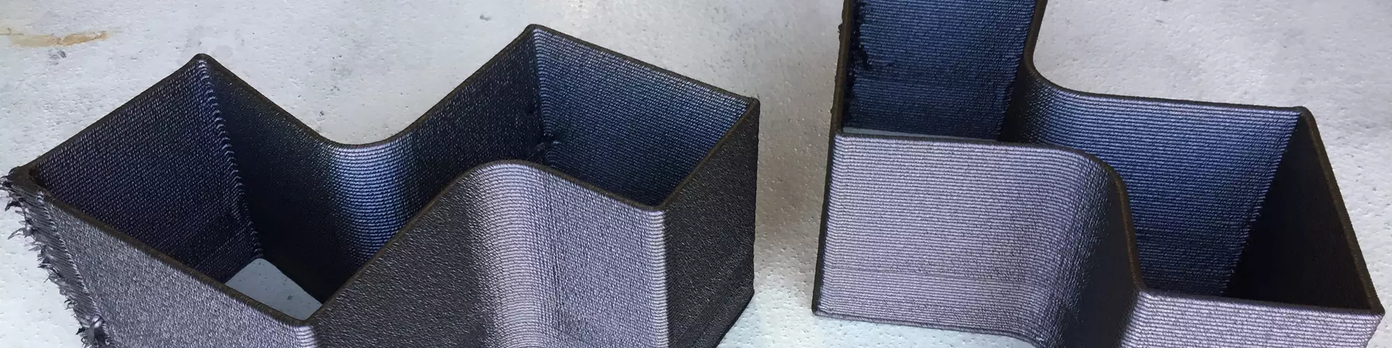
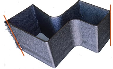
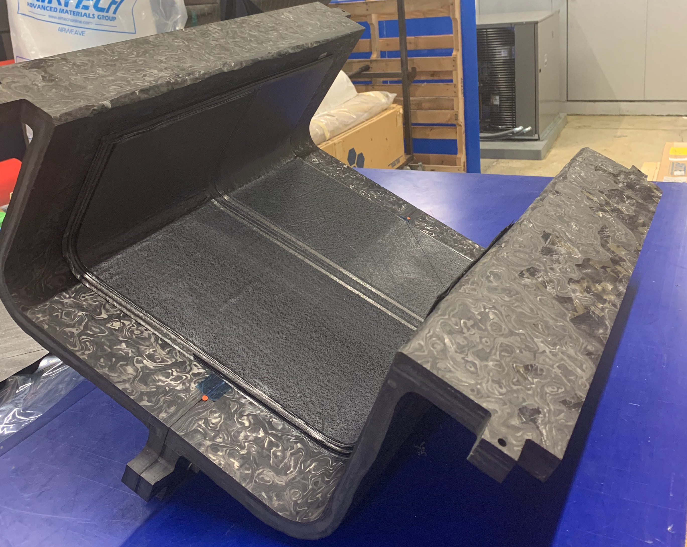
Geometry of subscale (0.6-meter) tool showing inward angle/negative draft on spar caps (yellow circles) that led researchers to decide to split the tool (red circle), which was sealed with a silicone gasketing material. Reverse flanges just above yellow circles are outside of the part boundaries but were added to increase lateral stiffness of the tool. Photo Credit: University of Dayton Research Institute.
The team decided to use a sandwich structure to produce single-sided tooling for a section of a generic wing spar using tool data from Airbus. Other than producing tooling to mold only a section of the full-scale C-spar — owing to space limitations at the UDRI facility — no major design change was made.
A female tool was designed to ensure that critical part geometry was formed using hard-tooled surfaces. This spar cap tool had a slight inward angle that created negative draft and a die-lock condition, being a single-piece tool. This led researchers to modify the design to a split-tool that was sealed using gasketing/cordstock. To mitigate risk, the team began with a 0.6-meter/2.0-foot subscale tool to prove out the concept. Once the tool-development process and prototype parts produced on that tool were tested and found to work, the team built a larger 3.3-meter/11-foot-long tool to mold a larger section of the spar for prototype testing.
Since CFRP tooling has such a low CLTE value, is lighter than Invar and the tool was for prototype/low-volume production parts, the team decided to use CFRP face skins to constrain the AM core. The skins were made with Hextool M81 epoxy tooling prepreg from Hexcel (Corp., Stamford, Conn., U.S.).
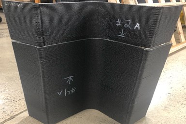
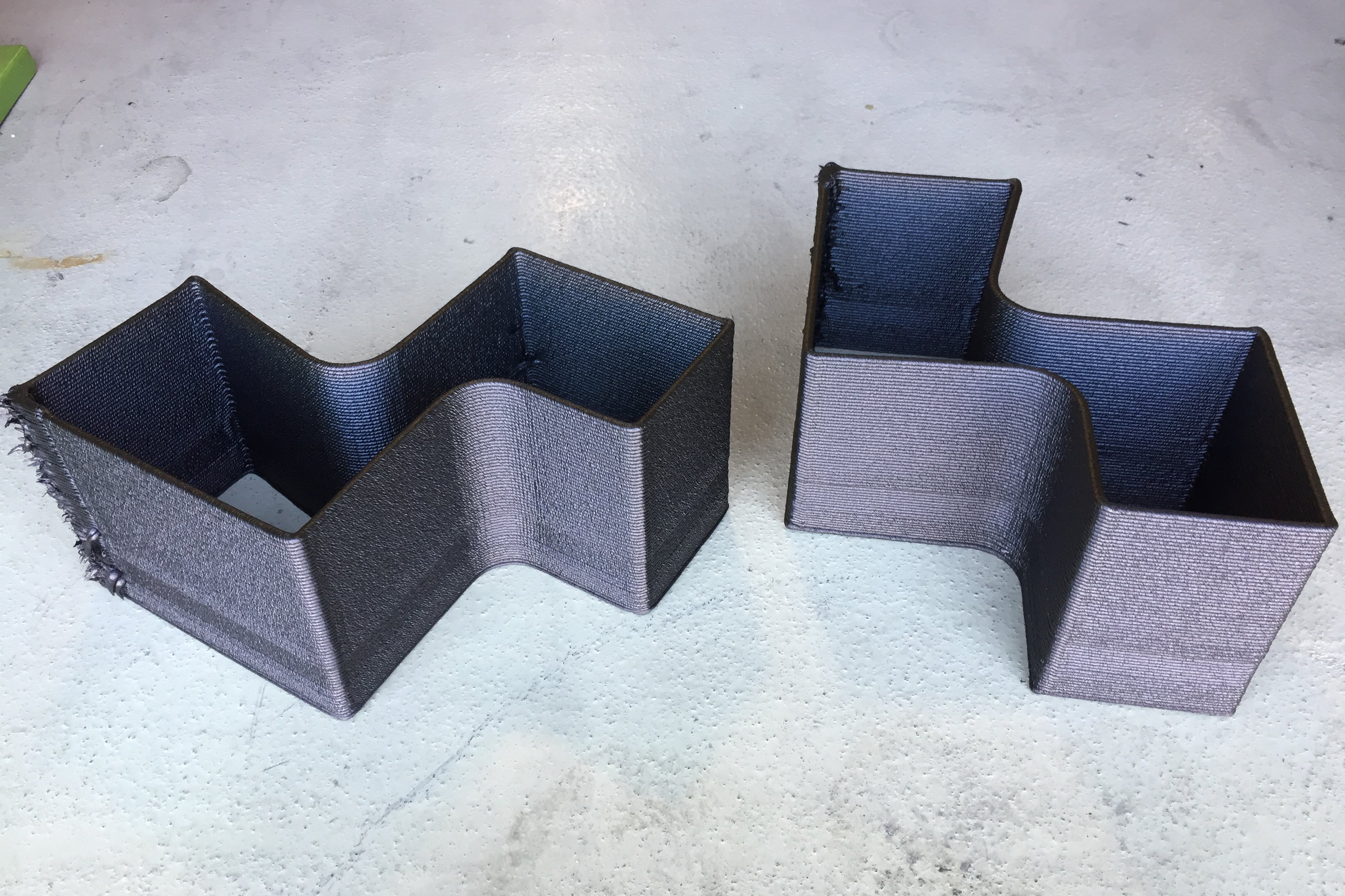
The top image shows one section of the right half of the subscale, BAAM-printed tool with red lines denoting cut lines after printing. The bottom image shows the right half tool after the sections were bonded together. Photo Credit: University of Dayton Research Institute.
Material format was a 2,000-grams-per-square-meter/59-ounces-per-square-yard mat of chopped carbon fiber impregnated with Hexcel’s 8552 toughened epoxy. This material is often used for composite tooling owing to its nearly isotropic properties, which permit post-mold machining without tool movement that might otherwise be caused by residual stress relaxation.
Given that the core would be printed on a Cincinnati Inc. BAAM 1000 printer at Additive Engineering Solutions (Akron, Ohio, U.S.), and given that UDRI and Cincinnati had significant experience working with the high-temperature thermoplastic polyetherimide (PEI), they selected 20% short carbon fiber-reinforced PEI (Thermocomp EX004EXAR1 Ultem) from SABIC, (Riyadh, Saudi Arabia) to print a near-net-shape core. (The presence of carbon fibers stabilizes the polymer during printing and prevents it from slumping; in the finished structure, the fibers reduce CLTE in the print direction.) To keep costs low, the core functioned as the tooling master and face skins were laminated directly to the core without adhesive, but with some modification to the core surface that is covered under intellectual property (IP) developed during the project. That approach was effective, with no delamination even after multiple thermal cycles.
Condensed manufacturing
In conventional fabrication of aerostructure CFRP tooling, a low-cost master is first created. This usually involves bonding together blocks of tooling board in an oven or autoclave, then machining the monolithic structure to the desired part geometry. The tooling material is then laid up, bagged and cured on the master in an autoclave. After demold and clean-up, a backing structure is bonded to the tool and the tooling surface is once again machined to ensure good geometric tolerance and surface finish.
With hybrid AM tooling, the team developed a condensed manufacturing process to reduce lead time and costs. First, a near-net-shape core (tool master) was 3D printed (in short-carbon fiber/PEI). Next, CFRP tooling prepreg was directly laminated onto both sides of the core (with hot debulks between plies one, four, and seven per the supplier’s recommendations). The entire structure was then vacuum-bagged and autoclave-cured.
Condensed manufacturing process for subscale C-spar tool.
Step 1: 3D print near-net-shape core (tool master) on BAAM 1000 printer (early design shown).
Step 2: Cut BAAM print down the middle and into left and right halves.
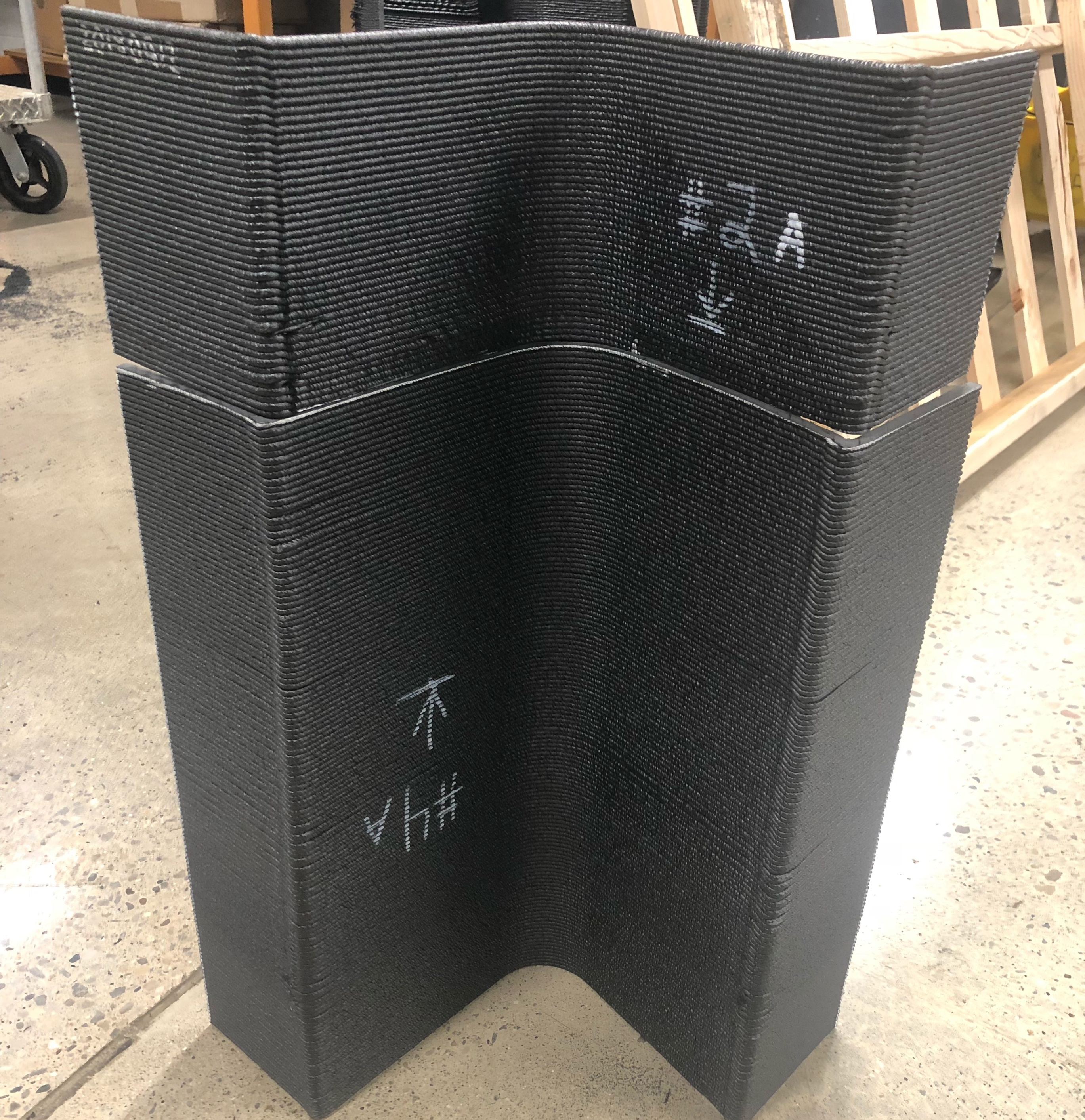
Step 3: Bond BAAM print to achieve required length and let cure.
Step 4: Laminate tooling prepreg to both sides of core with hot debulks per manufacturer’s instructions.
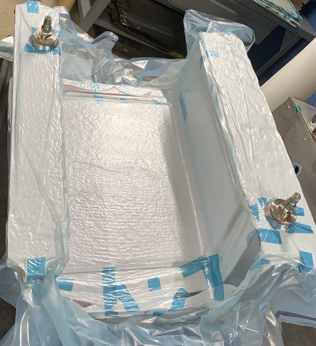
Step 5: Vacuum bag and cure in autoclave.
Step 6: Machine cured tool to achieve final dimensions and surface finish.
Good adhesion was achieved between the PEI core and epoxy skins during laminate cure, so adhesive was not required. Not only are the CFRP skins non-porous and more durable than the AM core, they also physically constrain movement of the core during temperature excursions due to their much-lower CLTE values. Only a single cure and a single machining operation — both major expenses during traditional tool production — were needed to achieve final dimensions and surface finish. Also, no backing was required, owing to the sandwich structure and tool shape, which included return flanges at the top of the mold for lateral stiffness and a bolted joint at the center of the mold for vertical stiffness — eliminating a bonding operation.
Initial challenges
Researchers faced several manageable challenges with the new process.

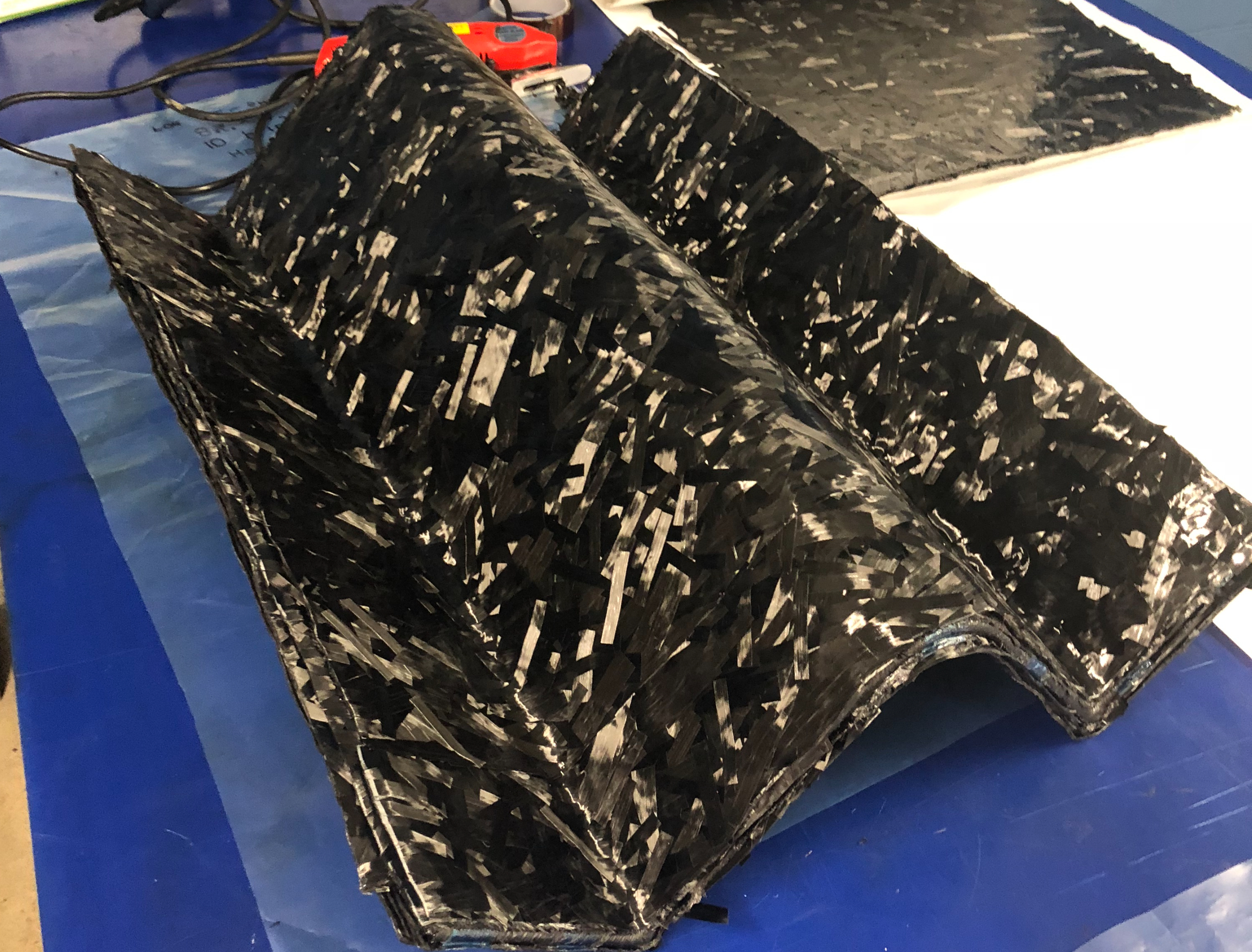
C-spar laminate laid up into tool. Photo credit: University of Dayton Research Institute.
For ease of manufacture on the BAAM, the preferred manufacturing direction for the core was printing the cross-section as a vertical build. That wasn’t a problem for the 0.6-meter tool; however, for the larger tool, 3.3 meters was taller than the BAAM 1000 could print vertically. Due to the printer’s Z-axis printing-space limitations, researchers opted to halve both subscale tools down their length and then split them again into left and right sections (to address spar-cap undercut issues and facilitate demolding).
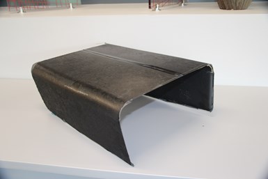
C-spar laminate after demolding. Photo Credit: University of Dayton Research Institute.
To increase printing efficiency, tool sections were printed back-to-back and then cut into right- and left-hand pieces. To achieve the 3.3-meter length, the two right-hand sections were bonded together followed by the two left-hand sections using Henkel Corp.’s (Rocky Hill, Conn., U.S.) Loctite EA9394 epoxy adhesive. The team left the AM core unmachined, feeling that was critical for achieving low tooling costs and short lead times, as well as to create a mechanical interlock between the AM core and the CFRP skins on each side. The back side of each tool half was laminated with five plies of prepreg while the front side was laminated with nine plies to provide extra material that could be removed during post-cure machining.
Preliminary results
In addition to controlling CLTE of the AM core, the prepreg provided a pit-free surface that maintained vacuum integrity without need for sealant/coating. This approach was so successful that it permitted use of a multi-piece tool design sealed with a gasket, which researchers believe had not previously been demonstrated in AM tooling used at high temperatures. Additionally, tool mass was reduced significantly; the subscale tool was one-third the weight calculated for a comparable Invar design. Not only are lighter CFRP tools easier to handle and store on racks, but they also require shorter autoclave heat up/cool down cycles. On a tool to mold the full-scale C-spar, that weight advantage could make the difference between being under or exceeding gantry/crane weight limits in some manufacturing spaces.
Importantly, the 0.6-meter hybrid tool cost was calculated during manufacture, using industry-standard labor rates, at $24,136 USD with roughly a 50/50 split between machining costs and printing/laminating costs. In contrast, an identical Invar tool was quoted at $46,775 USD — an almost 50% savings. Costs for the 3.3-meter tool are not complete but are expected to yield roughly 30% savings on a cost/unit length basis, as material/printing costs scale linearly, but machining costs enjoy an economy of scale that reduces its impact. The hybrid approach produced tools that met the operational performance requirements of Airbus and Northrop Grumman and is considered a viable alternative to Invar for rapid-prototype or low-use tooling. Tool-life investigation was not part of this study, but likely would extend considerably beyond the 12 cycles that were demonstrated.
The program was extended from 18 to 30 months, but there are still areas where more study is needed, such as understanding how final as-printed core geometry differs from that predicted in CAE models. The team also wants to improve predictive accuracy so that enough plies are added in critical areas to ensure there is no punch-through during machining. Still, the team considered this a successful project with considerable opportunity for future LFAM tooling.
“Northrop Grumman is looking forward to building a 3-meter spar demonstration part using the 3.3-meter-long hybrid tool built by UDRI and our own automated stiffener forming (ASF) process to evaluate the durability and dimensional stability of the tool,” adds Vern Benson, Northrop Grumman technical fellow.


.jpg;maxWidth=300;quality=90;format=webp)


Related Content

Plant tour: National Institute for Aviation Research, Wichita, Kan., U.S.
NIAR, located at Wichita State University in the heart of the American aerospace manufacturing industry, has evolved to become a premier hub of teaching, R&D, creativity and innovation.
Read More
Overair's Butterfly eVTOL prototype to integrate composites-intensive design
Aiming for first flight tests in the latter half of 2023, Overair’s Butterfly aircraft uses Toray carbon fiber/epoxy prepreg strategically to cut weight on its battery-powered, quiet aircraft.
Read More
SuCoHS project: Advancing composite solutions for parts with high thermal and mechanical loads
New materials, structural concepts and manufacturing using sensors for composites that resist fire, temperature and loads while providing weight and cost savings versus metals.
Read More
DLR completes MFFD upper shell skin layup
Eight-meter-long CFRTP fuselage skin was achieved via laser-heated in-situ consolidation, with stringers, frames and cleats to be welded.
Read MoreRead Next

Additive manufacturing: Big and going commercial
A demonstration of large-format 3D printing delivers parts for an excavator cab, from CAD data to ready for assembly, in only five hours.
Read More
Composites end markets: Energy (2024)
Composites are used widely in oil/gas, wind and other renewable energy applications. Despite market challenges, growth potential and innovation for composites continue.
Read More
CW’s 2024 Top Shops survey offers new approach to benchmarking
Respondents that complete the survey by April 30, 2024, have the chance to be recognized as an honoree.
Read More