
Plant tour: Harris Corp., Rochester, N.Y., U.S.
High-technology telescope and space structures expertise has its roots in legacy Kodak programs.

Harris Corp. acquired Exelis Inc. Geospatial Systems in 2015, and CW got the chance to tour the Geospatial Systems facility, located in Rochester, NY, US. Formerly part of camera and photographic film giant Kodak, the site helped pioneer satellite film surveillance technology and today continues to specialize in satellite and telescope structures. Source (all photos): Harris Corp.
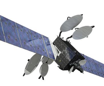
Harris produces the bus structures for its customer Orbital ATK’s GEOStar-3 communications satellite, shown here. The central support structure is a composite made with high-modulus carbon/cyanate ester prepreg supplied by TenCate Advanced Composites USA Inc.
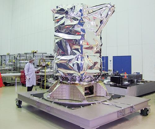
A nearly complete GeoEye satellite structure is shown in the integration facility of the High Bay area. The structure is encased in its multi-layer insulation (MLI), consisting of multiple layers of Kapton, a polyimide with good ultraviolet radiation resistance. 
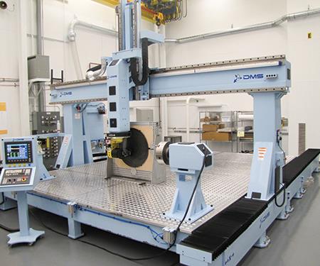
Harris relies on high-accuracy, 5-axis CNC machining centers such as this one from Diversified Machine Systems (DMS), one of several the company employs for both composites and metals, in support of critical part fabrication for its satellite structures.
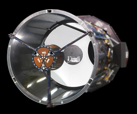
Harris’ 1.1m commercial imaging telescope is shown here. The composite telescope structures are designed to have zero CTE (coefficient of thermal expansion) and near-zero CME (coefficient of moisture expansion), and are made with a proprietary hybrid laminate that combines two different fibers to optimize performance.
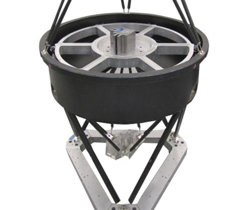
This photo demonstrates how the tubular carbon composite struts, a Harris specialty, are used to support the elements of a telescope, in “bi-pod pairs.” Kinematic mounts minimize strain, and the struts control each degree of freedom for maximum stability. The composite materials exhibit zero CTE.


Flashback 55 years to May 1960: An American U-2 spy plane, equipped with photographic equipment for taking high resolution photos of the Soviet Union, is shot down by the Russians and its pilot, Francis Gary Powers, is captured. The incident creates a major foreign- policy headache for President Eisenhower and squelches a planned peace summit. Eisenhower orders an end to U-2 overflights of the USSR shortly after the incident, but unbeknownst to most US citizens, new technology is already in place: The US government’s Corona program reconnaissance satellites, equipped with powerful Kodak film, are already collecting images of the USSR for the US Central Intelligence Agency. The company behind the Brownie camera was in fact involved, via Corona, in top-secret photo technology that wasn’t declassified until 1995.
Although those programs are long over, the Kodak group in Rochester that was involved in those space reconnaissance programs was eventually spun off and absorbed by ITT, which later became Exelis Inc. Geospatial Systems (McLean, VA, US). Exelis was acquired in 2015 by Harris Corp. (Melbourne, FL, US), a specialist in advanced electronics and communications technology. CW had the opportunity to tour the Harris facility in Rochester, with Joe Phillips, the director of Harris’ Precision Structures group, and Irene Lockwood, a communications manager at Harris, as guides, to see satellite production first-hand.


Engineered, and tested, for space
Phillips directs a sizeable workforce that is currently designing, fabricating and testing stability-critical telescope structures as well as other customer projects, including GEOStar-3 communications satellite bus structures for customer Orbital ATK (Dulles, VA, US), in a carefully controlled systems-engineering process: “We build to spec as well as to print, depending on the customer,” he says. The group includes nearly 50 engineers, including specialists in dynamics, thermal performance, materials, structures, electrical and process engineering, as well as industrial engineering. Analysis and design software used by the engineering staff includes Nastran from NEI Software (Westminster, CA, US), Patran from MSC Software (Newport Beach, CA, US) and Pro/Engineer (now PTC Creo Parametric) from PTC (Needham, MA, US). Although it is related to the Harris (former Exelis) facility in Salt Lake City, UT, US, Phillips clarifies that the Salt Lake City group is involved in high-volume manufacturing, primarily on the commercial aircraft side, while in Rochester, “we design, analyze, fabricate and test custom solutions where the volumes are typically one to five units. Our quality management system is certified to AS9100.”
The tour actually begins near the end of the process, in the environmental testing laboratory, which Phillips says represents a “big part” of his group’s efforts. There, a completed “thrust tube,” or composite cylinder, approximately 3m tall,1.3m in diameter and built to support the propulsion system for an 8-kW communications satellite, is mounted in a static load test tower in preparation for tests that simulate launch loads, to demonstrate workmanship and part acceptance for customers. The group produces the thrust tubes in a variety of diameters (all about 3m long) specific to each customer’s project. They act as a satellite’s backbone, explains Phillips, to which fuel and oxygen tanks, electrical boxes, antennae and much more are attached.
The testing laboratory is equipped to record strain data on 380 channels, 32 channels of acoustic emissions and has available 32 linear variable displacement transducers (LVDTs) to measure the smallest movements or displacements in the structure, with testing load control provided by software from MTS Systems Corp. (Eden Prairie, MN, US). The lab also is equipped with a horizontal and vertical shaker, located in a Class 10,000 cleanroom, for tests that require contamination control.
“We’ve been producing optical systems for more than 50 years here,” says Phillips. “Think of satellite images you see on TV or online, or space telescopes — thermal and dynamic stability is critical to maintaining focus and pointing, which is validated by extensive testing.”
Tests for composite workmanship also include thermal cycling in vacuum and under ambient conditions, in temperature- controlled chambers, and during acoustic tests, vibration tests, and modal-excitation tests, which determine the harmonics generated during excitation on a shaker table. Phillips explains the modal data are correlated with finite element analysis (FEA) to ensure that no harmful or even destructive modes occur during launch and operation. For static testing, a load test tower dotted with hundreds of tapped holes allows for rapid setup of customized load trains for any size part, with load actuators situated in any orientation. “Our flexible test tower and standard load trains allow our engineers to quickly design a test to simulate launch conditions while minimizing the number of configurations required to fully exercise the structure,” asserts Phillips. He also points out an “Iron bird” test in progress on one test stand, which refers to a steel dummy part that is tested first, at twice the maximum load, to ensure that the test equipment itself is operating optimally before the costly composite part is tested. And, he describes additional laboratory space that houses a complete composite material characterization lab, for coupon testing in accordance with ASTM International standards.
More testing is conducted in the mechanics calibration and measurement (MCM) laboratory next door, which houses a Summit coordinate measuring machine (CMM) supplied by View Micro-Metrology (Tempe, AZ, US). Phillips describes how tubular composite strut structures, used for secondary mirror supports, are tested in the MCM Lab: “We bag the part, then immerse it in a tube of water, and the water is slowly heated. A laser interferometer device, a precision measuring system for motion, detects any growth in the tube due to thermal expansion.” The coefficient of thermal expansion (CTE) acceptance for carbon composite struts, every one of which is tested, is 0 ±0.08 ppm/0F. He goes on to say that for years, Invar was used for certain structural elements, for its very low CTE and good stability. But, the group transitioned to zero-CTE carbon/epoxy materials to add weight savings in the 1980s: “Our niche is really understanding the properties of a wide variety of materials, composite and metal, and their performance in the space environment, and how to select the best materials to support specific payloads,” adds Phillips.
Precise optical structures and composite supports
Before getting into details of actual composite fabrication, Phillips first shows CW how the optical mirror systems, which eventually are mounted within the composite thrust tube structural supports, are produced and tested. In this area, booties, hair nets and lab coats are required, along with safety glasses. Called the High Bay, the room contains eight enormous optical test chambers, 11m in diameter and 21m tall, around which the building was originally constructed. These chambers, equipped with support frames for the tested assemblies, simulate deep space conditions. Hard vacuum and large radiators produce high heat; intense cold is generated via liquid nitrogen. Each chamber “floats” on supports that completely isolate it from any vibration generated within the factory during tests. “Even fluorescent lights can affect a test, since they operate at 60 Hz and create slight vibration,” says Phillips.
The chambers are used to test and validate the optical performance of the mirrors used in optical telescope assemblies for Earth observation and other applications. Mirrors are produced from ultra-low expansion (ULE) glass blanks made by Corning Inc. (Corning, NY, US). The “boules” or blanks used to fabricate the mirror’s honeycomb-shaped core are first waterjet cut to approximate shape. Additional glass boules, used to form the facesheets, are ground and shaped prior to joining to the core, then are carefully polished using several methods. The final glass figure is achieved with an argon laser in a process called ion figuring; the laser beam shapes and polishes the glass surface at the molecular level, producing a high-precision surface. “Our FEA models predict the sag in the mirror’s surface here at the facility, in Earth’s gravity. The predicted displacements are subtracted from actual surface measurements and the delta becomes a hit map for the ion-figuring process to produce an optical surface that, when in orbit, assumes the correct shape in zero gravity,” says Phillips. Kodak pioneered this ultra-precision mirror production process and the Rochester facility of Harris has supplied several major Earth observation imaging systems and sensors, including GeoEye-1 and WorldView-1, -2, -3 and -4.
At the other side of the large High Bay, in the integration facility, Phillips points out several optical telescopes that are undergoing assembly, with the addition of electronics, wiring and other necessary equipment in progress. He also notes the multi-layer insulation (MLI) materials, supplied by Sheldahl (Northfield, MN, US), that line the telescope’s outer surfaces —15 to 25 layers of aluminized Kapton (a polyimide with good ultraviolet radiation resistance), with each layer separated by polyethylene scrims. The telescopes are designed to maintain positive thermal control by cold-biasing the system and adding heat via Kapton heaters, Phillips says.
To support the optics, however, composite structure is a necessity. The tour proceeds on to the Low Bay portion of the building, which houses composites manufacturing, all of which is hand layup. Phillips shows a fabrication area where large (2.5m by 7m and 2.5m by 4m) heated platen presses produce the flat honeycomb panels, typically about 12.5 mm thick, that surround a thrust tube to create complete satellite bus structures and other satellite components. Core is typically aluminum honeycomb with skins of out-of-autoclave cure-capable, high-modulus M55J carbon/RS3C cyanate ester prepreg supplied by TenCate Advanced Composites USA Inc. – Fairfield (Fairfield, CA, US). Phillips explains that the heated platens also are used to consolidate radiator panels, which contain embedded heat pipes filled with ammonia that act to dissipate heat generated by spacecraft components. “The liquid ammonia flows to the hot spot via capillary action. As it absorbs heat, it vaporizes and travels back to the cold spot via the center of the tube, where it condenses and the process repeats. It’s a passive radiator or heat exchanger that keeps the electronics and optics from overheating.”
Next, Phillips and Lockwood show where the cylindrical thrust tubes, described above in the environmental test laboratory, are fabricated and incorporated into the satellite structures. Again, TenCate’s high-modulus M55J carbon/RS3C cyanate ester unidirectional prepreg is used to produce what appears to be absolutely flawless laminates. To assemble the bus structure, a master assembly tool (MAT) is used to hold each element in place during match bonding, including the radiator panels. The wheeled thrust tube mandrel can be easily rotated to facilitate layup, and transfers parts to the adjacent 5-axis machining center for required machining to accommodate the many attachment points to which satellite elements must be affixed.
In another fabrication area, we see technicians lay up curved radio frequency dishes for a proprietary program, using sandwich construction. Dish-shaped male molds are supplied by Lynco Grinding Co. Inc. (Bell Gardens, CA, US), although Phillips says that Harris is starting to fabricate select layup tools in house. The material selection, tool design and processes selected to fabricate the reflectors are critical factors that must be considered in order to meet operational performance requirements, explains Phillips.
Harris is well known for its tubular struts, used in many applications. Phillips explains that the struts are frequently deployed in three “bi-pod pairs,” which controls each degree of freedom of the mounted component. The kinematic mount minimizes mount strain and environmentally induced thermal strain due to varying temperatures and material properties. The proprietary composite tubes, ranging from 6.5-mm to 200-mm inside diameter, are produced on metal mandrels, says Phillips, “The fibers and resin are blended in a way that results in a zero-CTE laminate with a modulus as high as 62 Msi in the axial direction.”
A digital factory, with continuous improvement
At this point, the tour passes through a quality control area, and Phillips pauses to describe the “digital factory” procedures that have been put in place, including ubiquitous bar coding on all materials and parts, electronic work instructions (EWI) and the linking of CAD files to technician’s actions on the factory floor that “have improved our manufacturing processes and speed.” Using adhesive mixing as an example, which is an important part of the group’s cored composite panel-fabrication process, he relates that all steps of mixing are now better controlled, from selecting the correct (bar-coded) adhesive for a particular task, to the mixing process itself; three planetary mixers from Thinky USA (Laguna Hills, CA, US) are employed to provide more consistent blending and better air elimination, improving adhesive performance. All adhesive bonds, he adds, are tested as part of the quality control process, using single lapshear coupon testing, per ASTM standards.
Throughout the rest of the Low Bay facility, Phillips points out the sheet metal fabrication area and machine shop for metal fab, which includes a Summit Machine Tool Mfg. (Oklahoma City, OK, US) milling machine equipped with vacuum, and a 1.85m by 3.7m by 4.3m work envelope, and a five-axis CNC machining center from Diversified Machine Systems (DMS, Colorado Springs, CO, US). Two autoclaves from ASC Process Systems (Valencia, CA, US), 1.2m by 1.85m and 1.85m by 3.7m, are available, as is an adhesive film reticulator, a machine that deposits an adhesive film only along the cell edges of honeycomb core, prior to facesheet bonding. In a material prep area, an Eastman Machine Co. (Buffalo, NY, US) automated cutting table “has improved our efficiency tremendously,” states Phillips. Debulk tables, a bagging area and a freezer for prepregs are part of the material handling area (two freezers are located off site, as well).
As our tour ends, Lockwood notes that Harris technology has been on every US global positioning system (GPS) satellite ever launched, and the company is involved with weather monitoring and forecasting programs, NASA communication networks for satellite tracking, and the James Webb Telescope. And space applications aren’t the only projects Harris handles. Recent solutions under “other” include a large, ground-based radar structure that had challenging stability and weight requirements given the harsh operational environments. Another is a composite inspection machine for a computer chip manufacturer in California that required rapid movement, at high production speeds, but very accurate dynamic control.
Concludes Phillips, “We’re in a unique position, with our history, materials knowledge and capabilities, and our engineering staff, that allows us to produce key systems for many customers where strength and stability are critical.” The company’s rich legacy, coupled with its composites expertise, promises a successful future.


Related Content

Materials & Processes: Tooling for composites
Composite parts are formed in molds, also known as tools. Tools can be made from virtually any material. The material type, shape and complexity depend upon the part and length of production run. Here's a short summary of the issues involved in electing and making tools.
Read More
Plant tour: Albany Engineered Composites, Rochester, N.H., U.S.
Efficient, high-quality, well-controlled composites manufacturing at volume is the mantra for this 3D weaving specialist.
Read More
One-piece, one-shot, 17-meter wing spar for high-rate aircraft manufacture
GKN Aerospace has spent the last five years developing materials strategies and resin transfer molding (RTM) for an aircraft trailing edge wing spar for the Airbus Wing of Tomorrow program.
Read More
RUAG rebrands as Beyond Gravity, boosts CFRP satellite dispenser capacity
NEW smart factory in Linköping will double production and use sensors, data analytics for real-time quality control — CW talks with Holger Wentscher, Beyond Gravity’s head of launcher programs.
Read MoreRead Next

From the CW Archives: The tale of the thermoplastic cryotank
In 2006, guest columnist Bob Hartunian related the story of his efforts two decades prior, while at McDonnell Douglas, to develop a thermoplastic composite crytank for hydrogen storage. He learned a lot of lessons.
Read More
Composites end markets: Energy (2024)
Composites are used widely in oil/gas, wind and other renewable energy applications. Despite market challenges, growth potential and innovation for composites continue.
Read More
CW’s 2024 Top Shops survey offers new approach to benchmarking
Respondents that complete the survey by April 30, 2024, have the chance to be recognized as an honoree.
Read More