
Fracture mechanics testing of composites
Dr. Daniel O. Adams, professor of mechanical engineering and director of the Composite Mechanics Laboratory at the University of Utah, and vice president of Wyoming Test Fixtures Inc. (Salt Lake City, UT, US), addresses ways to acquire mechanical test data and then calculate the values for the composite material property of fracture toughness.

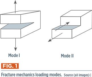
Fig. 1: Fracture mechanics loading modes. Source (all images) | Dan Adams
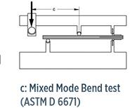
Fig. 2: Test methods used for fracture mechanics testing of composites.


Unlike most mechanical tests that measure stiffness and strength properties, fracture mechanics testing addresses the growth of delaminations in composite laminates. The property measured is the material’s critical energy release rate, Gc, or fracture toughness. This experimentally measured value of G is compared to the available energy release rate, obtained from engineering analysis, to determine whether a composite delamination will propagate under a particular loading condition. Just as different test methods are used to measure stiffness and strength properties under tension, compression and shear loading, there are different fracture toughness test methods and properties associated with three modes of delamination loading (Fig. 1, at left). Mode I corresponds to an interlaminar tension loading and is the most commonly performed fracture mechanics test. Mode II corresponds to interlaminar shear loading, and is also commonly used when predicting delamination growth. Mode III corresponds to less commonly tested interlaminar “scissoring” shear loading. In actual composite structures, delaminations are subjected to a combination of loading modes and, thus, the fracture toughness corresponding to mixed-mode delamination growth is required. Here, therefore, we will focus on Mode I, Mode II and Mixed Mode (Mode I and II) testing, for which standardized tests exist.
These three tests may be performed using specimens cut from identical 3-5-mm thick test panels in which a thin (13 µm) strip of non-adhering PTFE film is inserted at the laminate midplane during panel layup to produce the required implanted delamination. Unidirectional laminates, with fibers oriented in the direction of delamination propagation, are used to prevent delamination from migrating through the thickness to neighboring plies, invaliding test results.


Mode I testing is performed using the Double Cantilever Beam (DCB) test specified in ASTM D 55281. The specimen is 125 mm long, 25 mm wide, with a 63-mm long implanted delamination at one end. No specialized test fixturing is required, but loading hinges are bonded to the top and bottom surfaces for tensile loading the specimen’s delaminated end (Fig. 2a, at left). During the test, the displacement rate is a constant, and the applied load, crosshead displacement and delamination length are recorded as stable delamination growth occurs. Typically, specimen edges have been coated with white paint to aid in locating the delamination tip.
Although the DCB test is relatively simple to perform, calculating the Mode I fracture toughness from test results can be confusing. For starters, GIC is calculated using beam theory equations, assuming that the portions of the specimen above and below the delamination act as dual cantilever beams. But because the supported end of the “beams” are not truly cantilevered, the equations must be corrected, using a calibration procedure that uses measured specimen compliances obtained for several delamination lengths. ASTM D 5528 describes three methods for performing this calibration and provides corrections to the beam theory equations that adjust either the delamination length or the specimen compliance. Typically, all three (modified beam theory, compliance calibration, and modified compliance calibration) produce similar results. Modified beam theory is the recommended method, but all three are listed on the recommended data reporting sheet. Additionally, three methods are provided for determining the load at which delamination growth occurs, an input to GIC calculations. The options currently provided in ASTM D 5528 produce a total of nine values for GIC, but efforts are underway to reduce the number of values and provide more specific recommendations.
Although GIC can be calculated for any delamination length produced during testing, values often increase as the delamination propagates due to fiber bridging. That is, fibers remain intact across the delamination plane and resist delamination growth. Therefore, two initiation values of GIC typically are calculated, corresponding to the onset of growth from the implanted PTFE film as well as a short, natural precrack. Although GIC for growth from the film (non-precracked) typically is higher because of the blunt crack tip, it may be of use for predicting growth of some delaminations produced in composite structures during manufacturing. The precracked GIC value is typically lower, and considered more representative for delaminations produced from impacts and for progressive damage modeling.
For Mode II testing, the three-point End Notched Flexure (ENF) test was standardized as ASTM D 79052 in 2014. The 160-mm long ENF specimen is loaded using a conventional three-point flexure fixture, with the 45-mm implanted delamination extending to the midpoint between the outer and central loading points (Fig. 2b, at left). Because delamination growth is unstable, compliance data for calibration purposes are obtained at relatively low load levels, shifting the specimen in the fixture to produce three delamination lengths. Similar to the DCB test, GIIC values are obtained for the onset of growth from the implanted insert and a natural precrack. Unlike the DCB test, ASTM D 7905 specifies a single calibration method (compliance calibration) and recommends a single method for load determination (maximum load point), resulting in single GIIC values for the non-precracked and precracked conditions.
The Mixed Mode Bend (MMB) test method, standardized as ASTM D 66713 in 2001, combines the loading of the Mode I DCB and Mode II ENF tests using the configuration shown in Fig. 2c. Loading hinges are bonded to the delaminated end of the 150-mm long specimen and attached to the fixture base and the upper loading lever. Varying ratios of Mode I to Mode II loading are applied by adjusting the position of the translating loading saddle. Pure Mode II loading is produced when the loading saddle is positioned directly over the central loading roller (c = 0, Fig. 2c), resulting in three-point flexure loading. Increasing ratios of Mode I to Mode II loading are obtained by moving the loading saddle away from the specimen’s delaminated end, producing an increasing lever arm that opens the delaminated portions of the specimen, as in the DCB test. ASTM D 6671 provides equations for calculating the Mode I and Mode II components (GI and GII) and total fracture toughness, Gc. For most composite materials, Gc increases as the percentage of Mode II loading increases, and delamination growth transitions from stable to unstable.
Although equations have been proposed to predict mixed-mode fracture toughness values based solely on measured values of GIC and GIIC, MMB testing is often performed at varying mode mixities and a curve fit of the data is used to arrive at a mixed-mode fracture criterion for delamination growth in composites.
References
1ASTM D 5528-13, “Mode I Interlaminar Fracture Toughness of Unidirectional Fiber-Reinforced Polymer Matrix Composites,” ASTM International (W. Conshohocken, PA, US), 2013 (first issued in 1994).
2ASTM D 7905-14, “Determination of the Mode II Interlaminar Fracture Toughness of Unidirectional Fiber-Reinforced Polymer Matrix Composites,” ASTM International (W. Conshohocken, PA, US), 2014.
3ASTM D 6671-13, “Mixed Mode I-Mode II Interlaminar Fracture Toughness of Unidirectional Fiber Reinforced Polymer Matrix Composites,” ASTM International (W. Conshohocken, PA, US), 2013 (first issued in 2001).


.jpg;maxWidth=300;quality=90;format=webp)


Related Content

Thermoset-thermoplastic joining, natural fibers enable sustainability-focused brake cover
Award-winning motorcycle brake disc cover showcases potential for KTM Technologies’ Conexus joining technology and flax fiber composites.
Read More
Materials & Processes: Tooling for composites
Composite parts are formed in molds, also known as tools. Tools can be made from virtually any material. The material type, shape and complexity depend upon the part and length of production run. Here's a short summary of the issues involved in electing and making tools.
Read More
JEC World 2022, Part 3: Emphasizing emerging markets, thermoplastics and carbon fiber
CW editor-in-chief Jeff Sloan identifies companies exhibiting at JEC World 2022 that are advancing both materials and technologies for the growing AAM, hydrogen, automotive and sustainability markets.
Read More
Composite prepreg tack testing
A recently standardized prepreg tack test method has been developed for use in material selection, quality control and adjusting cure process parameters for automated layup processes.
Read MoreRead Next

Composites end markets: Energy (2024)
Composites are used widely in oil/gas, wind and other renewable energy applications. Despite market challenges, growth potential and innovation for composites continue.
Read More
CW’s 2024 Top Shops survey offers new approach to benchmarking
Respondents that complete the survey by April 30, 2024, have the chance to be recognized as an honoree.
Read More
From the CW Archives: The tale of the thermoplastic cryotank
In 2006, guest columnist Bob Hartunian related the story of his efforts two decades prior, while at McDonnell Douglas, to develop a thermoplastic composite crytank for hydrogen storage. He learned a lot of lessons.
Read More