
Fracture mechanics test methods for sandwich composites
HPC's testing guru, Dr. Donald F. Adams (Wyoming Test Fixtures, Salt Lake City, Utah), surveys the available fracture mechanics test methods for sandwich panels.
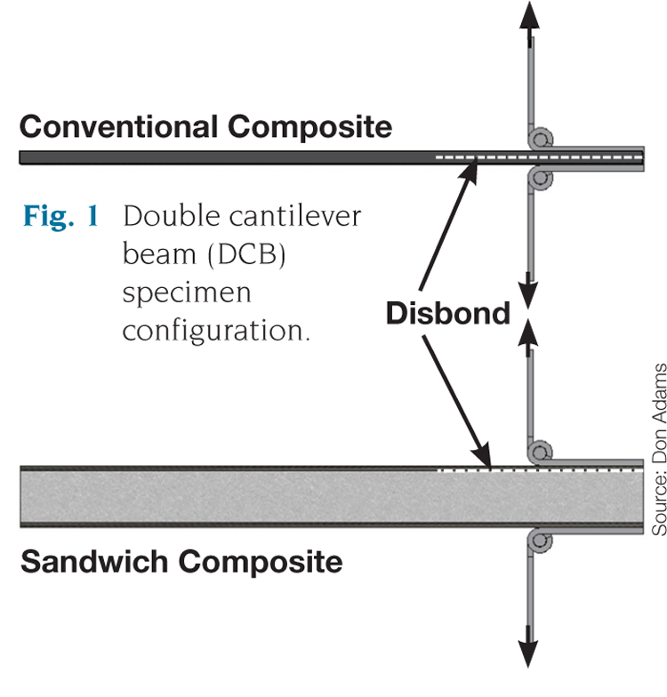
Fig. 1: Double cantilever beam (DCB) specimen configuration. Source: Don Adams
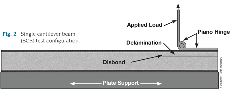
Fig 2: Single cantilever beam (SCB) test configuration. Source: Don Adams
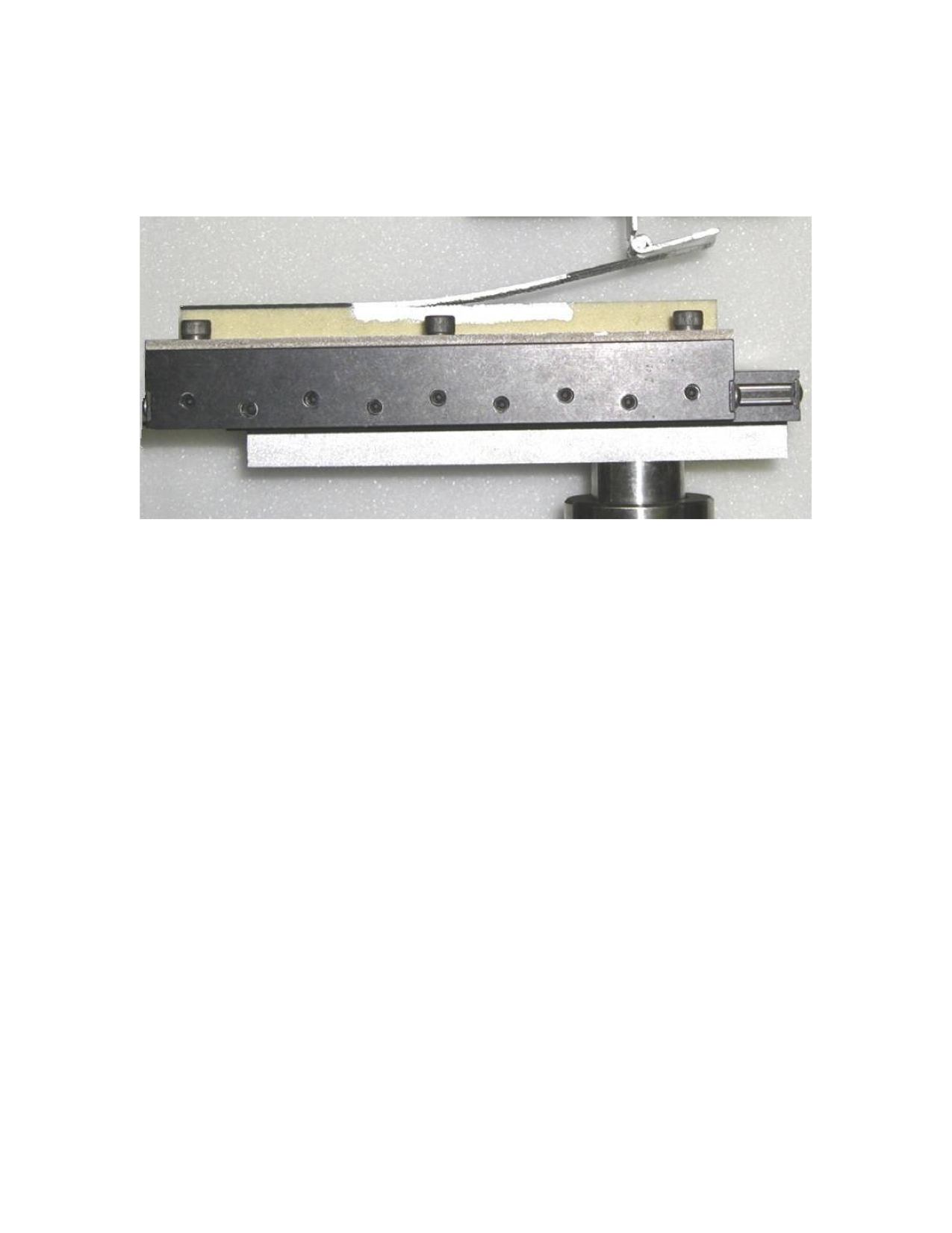
Fig. 3: An SCB test, performed using a translating base fixture. Source: Don Adams


Although well-accepted fracture toughness test methods are available for composite materials, the same cannot be said for sandwich composites. In fact, considerably less attention has been given to fracture mechanics test methods for sandwich composites until recently. A majority of the efforts, to date, have focused on developing a Mode I (opening mode) test method.
Before I discuss these efforts, however, I must point out an important difference between such test methods and the well-established peel tests for sandwich composites. Mode I loading for fracture mechanics test methods resembles that used in peel tests, such as the Climbing Drum Peel test (ASTM D1781). In peel tests of sandwich composites, the measured quantity is the peel strength, an indication of how well the facesheet is bonded to the core material. In contrast, fracture mechanics tests provide a measure of the fracture toughness, that is, a material’s resistance to growth of an existing crack. Although these two measured quantities may sound similar, their uses differ significantly. The peel strength obtained from a Climbing Drum Peel test is typically used for comparative purposes (e.g., to evaluate different adhesives or bonding processes) and for process control. Although fracture toughness measurements may be used for the same purposes as peel strength, they are more commonly used in product design and analysis, particularly when test personnel are addressing damage tolerance. Of particular interest in sandwich composites is the resistance to disbond growth at the facesheet-to-core interface.


Notice that I did not use the words material property when discussing the measured quantities from the two previously described test methods. This is because for sandwich composites, peel strength and fracture toughness depend not only on the facesheet materials, the core and the adhesive used in the sandwich construction, but they also can be highly dependent on the methods of fabrication and adhesive bonding. Therefore, these measured quantities should be considered structural properties of the as-fabricated sandwich composite rather than material properties.
The best way to describe the complexities associated with Mode I fracture toughness testing of sandwich composites is to begin with the existing test method for unidirectional composite materials — the Double Cantilever Beam (DCB) test method, standardized as ASTM D5528. Fig. 1 shows a conventional DCB specimen and the DCB specimen configuration adapted to a sandwich composite. In both specimens, an initial disbond is created at one end of the specimen. Each specimen is loaded using hinges bonded to the top and bottom of the specimen as shown. Note that in the conventional DCB specimen, the disbond is placed at the midthickness of the specimen, such that the upper and lower beam portions of the specimen are of the same thickness. For the sandwich DCB specimen, however, the initial disbond is placed at the location of interest, near the facesheet/core interface. Unfortunately, testing and analysis of this sandwich DCB configuration has identified several shortcomings. Although the starter crack is placed near the interface, crack growth is often into the core — an undesirable result. Additionally, the bending of the core and lower facesheet introduces considerable tensile stress into the core and can cause core failure.
In view of the problems associated with adapting the DCB test configuration to sandwich composites, researchers have looked at other test configurations. One of the most promising is the Single Cantilever Beam (SCB) configuration shown in Fig. 2.1 To prevent bending deformation in the core and bottom facesheet, the bottom facesheet is affixed to a lower support plate. Only the upper facesheet is considered a cantilever beam — thus the name Single Cantilever Beam. An upward load is passed through a hinge bonded to the upper facesheet on the specimen's debonded end. To maintain the vertical orientation of the loading during crack growth, a translating lower support plate can be used (Fig. 3). But a simpler solution involves the use of an extended loading rod, such that the applied load remains sufficiently vertical.2 Variations of this SCB test configuration have been investigated by other researchers.3,4
In view of the complexities associated with fracture toughness testing of sandwich composites, it might seem desirable to prescribe a standard specimen geometry and initial crack length in the SCB test. But there is a wide range of sandwich materials and sandwich geometries for which such a test may be used. It also is desirable to test composite sandwich specimens that are representative of the actual sandwich structure, as previously discussed. Given those realities, it might be necessary to design a suitable specimen geometry for each specific sandwich geometry that will be tested.2 Further, it might be that not all sandwich configurations are suitable for this test method, and it might be necessary to set bounds on suitable sandwich configurations as standardized test methods are developed. For example, bounds might be required on facesheet thickness so that proper beam behavior is produced during testing, making possible the calculation of accurate fracture toughness values.
Despite these complications, there is a need for fracture mechanics testing of sandwich composites. Standard methods, even with bounds and limitations, would be welcome. Efforts towards this goal are ongoing within ASTM's Committee D30 on Composites. For more information or to get involved, contact either Dr. Dan Adams at the University of Utah (adams@mech.utah.edu) or Dr. James Ratcliffe at NASA Langley Research Center (james.g.ratcliffe@nasa.gov).
Wyoming Test Fixtures Inc.
References:
1Adams, D.O., Nelson, J. and Bluth, Z. “Development and Evaluation of Fracture Mechanics Test Methods for Sandwich Composites,” proceedings of the 2012 Aircraft Airworthiness & Sustainment Conference, Baltimore, Md., April 2-5, 2012.
2Ratcliffe, J.G. and Reeder, J.R. “Sizing a Single Cantilever Beam Specimen for Characterizing Facesheet – Core Debonding in Sandwich Structure,” Journal of Composite Materials, Vol. 45, No. 25, 2011.
3Cantwell, W.J. and Davies, P. “A Test Technique for Assessing Core-Skin Adhesion in Composite Sandwich Structures,” Journal of Materials Science Letters, Vol. 13, pp. 203-205, 1994.
4Li, X. and Carlsson, L.A. “The Tilted Sandwich Debond (TSD) Specimen for Face/Core Interface Fracture Characterization,” Journal of Sandwich Structures and Materials, Vol. 1, pp. 60-75, 1999.


.jpg;maxWidth=300;quality=90;format=webp)


Related Content

CFRTP enables better, greener smartphones
Carbon Mobile’s “monocoque” design eliminates separate case, cover and frame, better protects electronics and simplifies disassembly.
Read More
Plant tour: National Institute for Aviation Research, Wichita, Kan., U.S.
NIAR, located at Wichita State University in the heart of the American aerospace manufacturing industry, has evolved to become a premier hub of teaching, R&D, creativity and innovation.
Read More
The basics of composite drawing interpretation
Knowing the fundamentals for reading drawings — including master ply tables, ply definition diagrams and more — lays a foundation for proper composite design evaluation.
Read More
Thermoset-thermoplastic joining, natural fibers enable sustainability-focused brake cover
Award-winning motorcycle brake disc cover showcases potential for KTM Technologies’ Conexus joining technology and flax fiber composites.
Read MoreRead Next

CW’s 2024 Top Shops survey offers new approach to benchmarking
Respondents that complete the survey by April 30, 2024, have the chance to be recognized as an honoree.
Read More
From the CW Archives: The tale of the thermoplastic cryotank
In 2006, guest columnist Bob Hartunian related the story of his efforts two decades prior, while at McDonnell Douglas, to develop a thermoplastic composite crytank for hydrogen storage. He learned a lot of lessons.
Read More
Composites end markets: Energy (2024)
Composites are used widely in oil/gas, wind and other renewable energy applications. Despite market challenges, growth potential and innovation for composites continue.
Read More