
Formula 1 team optimizes car design-to-build process
FEA-to-CAD translation tool opens doors to cross-department communication and frees up time for R&D and test-piece manufacture.
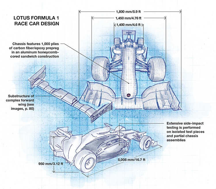
Lotus Formula 1 Race Car Design Illustration: Karl Reque
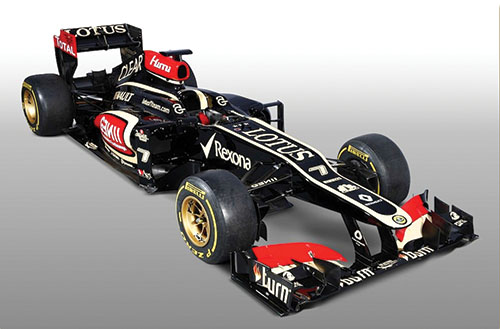
The 2013 Lotus Formula One E21 racer, designed using Siemens PLM Software’s (Plano, Texas) Fibersim suite, with Fibersim CAE Exchange, embedded in CATIA V5 (Dassault Systèmes, Paris, France). Source: Lotus
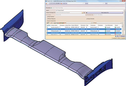
A composite definition has been re-imported from the FEA model into the forward wing CAD master model using Fibersim CAE Exchange. The cyan curves, originally jagged element mesh boundaries from CAE, have been refined using Exchange. Source: Siemens PLM Software
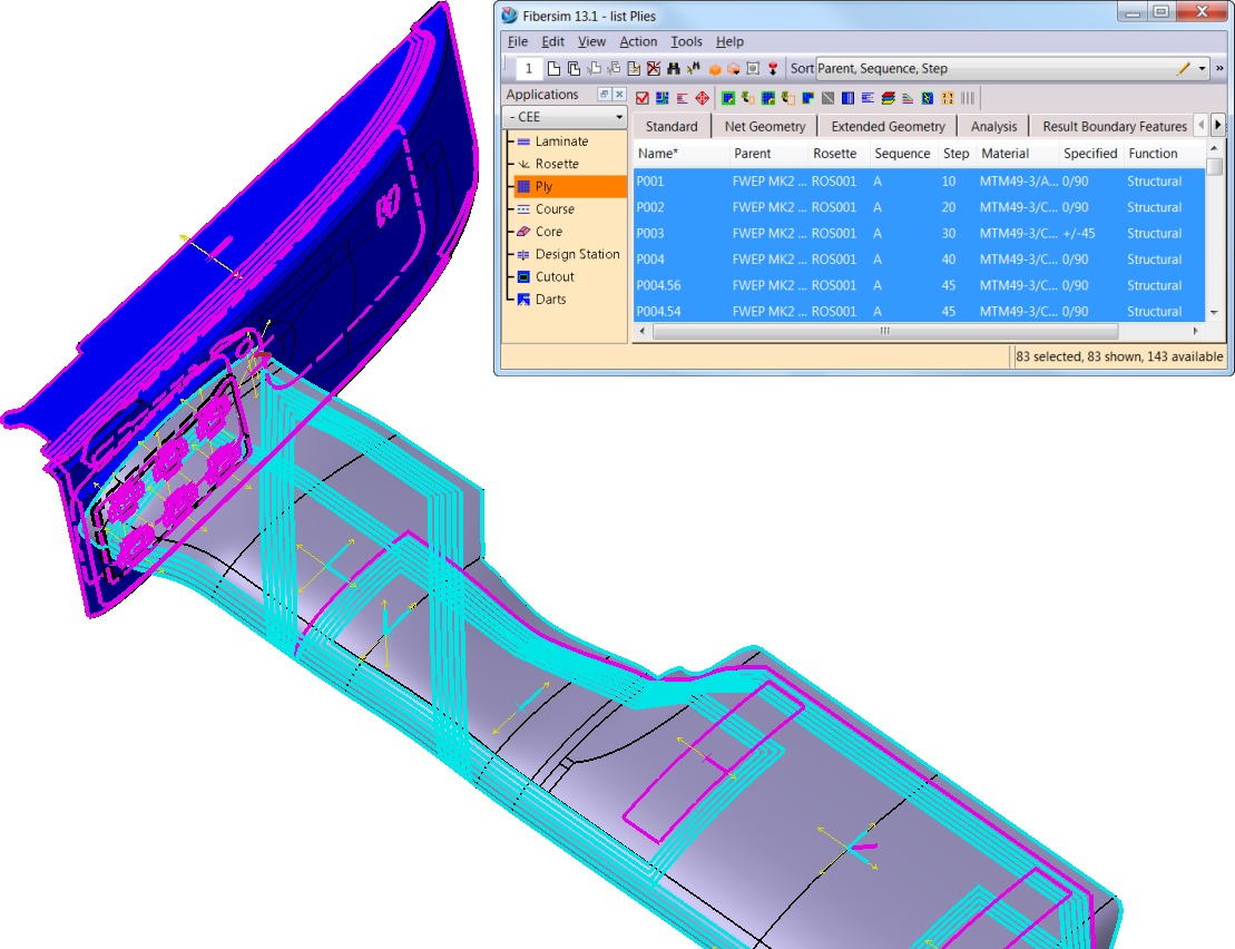
Fibersim has created a composite laminate definition within the forward wing CAD master model. Magenta and cyan curves represent the ply boundaries, while the double-headed arrows signify the warp fiber direction and method of layup. Source: Siemens PLM Software
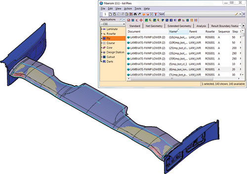
A ply within the CAD model has been simulated for manufacturing based on the part shape, material and lay-up method defined in Fibersim. Areas of blue indicate no layup issue, areas of yellow indicate a minor challenge with layup and areas of red indicate a manufacturing issue such as wrinkling. Source: Siemens PLM Software


Design Results:
- Fast and accurate information exchange between FEA and CAD provides time for additional design and testing phases and production chassis test articles.
- Cross-departmental communication between design, analysis and manufacture enables part and process optimization.
- Enhanced drape simulations and other methodologies mirror real-world lamination techniques to CAE analysts, who, in turn, can prescribe better layup practices.


Across between driving and flying, Formula 1 (F1) racing pushes the limits of mechanical and human possibilities. Car and driver reach speeds of up to 220 mph/354 kmh on the straightaway and experience G-forces that can top five in extreme corners. Manufactured primarily of carbon composites, the car, at 642 kg/1,415 lb, is less than one-third the weight of an average U.S. passenger car. Maximizing down force while minimizing drag is an elusive design goal. Each year F1 teams must perform this balancing act with increasing efficiency in a condensed, pressure-filled design cycle.
Moving from an aerodynamic concept to a carbon composite fit for the racetrack requires a large set of engineering tools and processes. It demands fast, accurate cross-department communication of data. For the Lotus F1 Team (Enstone, U.K.), the communication key is Fibersim, a composites software solution from Siemens PLM Software (Plano, Texas). The team has used Fibersim for more than 10 years, but design/build has accelerated significantly since Fibersim CAE Exchange was added in 2008 (see “Formula 1 team accelerates design-to-track speed,” under "Editor's Picks," at top right).
FEA-to-CAD translation
Fibersim is embedded in the Team’s CATIA V5 CAD environment (Dassault Systèmes, Paris, France) and supports its full CAE, design and manufacturing cycle for composite components. Fibersim CAE Exchange enables a two-way exchange between composite FEA models, used to verify stresses and loads, and the CAD master model, which captures car and component geometry and a plethora of other data, including aerodynamic analysis and wind tunnel algorithms.
“The exchange between CAE applications and Fibersim/CAD is accomplished directly, allowing Fibersim to use the composite definition and boundaries from CAE to create a composite CAD master model that is usable for design,” explains Leigh Hudson, Siemens PLM Software’s director of product and market strategy for Fibersim.
“Fibersim CAE Exchange was a major breakthough for us,” adds Ian Goddard, the team’s senior engineer and graduate program manager. “For the first time ever, we went from a tedious manual process to a true native conversion.”
Initially the software integration created a significant learning curve for the team’s design group. Nonetheless, in that first year the group achieved a 20 to 30 percent time savings in composite part design. “Five years down the line, we’re all very adept at understanding how the stress engineers work and knowing what the designers want to receive,” says Goddard.
Perfection isn’t good enough
At Enstone, 60 to 70 designers work year round on the racecar’s approximately 20,000 individual parts. Each year, the design work is split between tweaking the current year’s model, during a 19-race season that begins in mid-March, and major design revisions for next season’s car, condensed into a five-month period that begins in September.
It’s a daunting task. In all, 250,000 labor hours and 11,000 technical drawings (28 percent more than any previous car) went into the design of this year’s car. The team uses 30 types of carbon fiber materials and six different resins. Changes to the Fédération Internationale de l’Automobile’s (FIA) F1 safety standards add to the challenge. “There are refinements to the rules, year on year, particularly in side-impact penetration panels and general increased driver protection,” says Goddard. “So, we need to optimize the weight of the rest of the structure to minimize the impact of these statutory impact panels.”
Fibersim CAE Exchange buys the team time to meet these challenges by adding design phases and producing isolated test pieces and partial chassis assemblies. These are used to test novel solutions and do extensive side-impact testing research to determine how loads will be dissipated through the chassis. “Prior to 2008, our only goal was to make the single racecar chassis as fast as possible,” Goddard admits. “Now, we’re looking at construction using different structures, materials and other design approaches that we could never commit to when making a whole racecar.”
The initial design is based on the previous year’s chassis. Comprising 1,000 plies of molded carbon fiber and aluminum honeycomb, it is the car’s most complex laminate. “Even if we made the ‘perfect’ car last year, this year we still have to ask ourselves, ‘How do we make it stiffer, lighter and faster?’” quips Goddard. “The goal is always to take out as much weight as possible while maintaining the safety factors for the driver.”
A principal chassis part is the monocoque driver’s cockpit/survival cell, which is primarily a sandwich of aluminum honeycomb between high-density woven laminate panels. To protect the cell, tubular carbon side-impact structures are mounted perpendicular to the chassis side to absorb side-impact loads. Around these and covering the chassis side are anti-intrusion panels made of two plies of carbon fiber and 16 plies of Zylon PBO — poly(p-phenylene-2,6-benzobisoxazole) — supplied by Toyobo (Osaka, Japan). PBO reportedly has twice the strength and modulus of aramid fiber, resulting in a laminate thickness of only 6.2 mm/0.24 inch.
The survival cell is subjected to six different static load tests and absorbing structures endure three static side-load tests, with constant transverse horizontal loads up to 30.0 kN. Under the load, there must be no structural failure of the inner or outer cell surfaces, and total deflection must not exceed 15 mm/0.59 inch. “How the loads are transmitted through the side-impact tubes and dissipated into the side of the chassis are key to designing the optimum strong, lightweight composite chassis structure,” Goddard points out. “Hence, the benefit from having test programs to explore different ... laminate definitions.”
A common language
Fibersim CAE Exchange not only connects design, analysis and manufacturing data but also connects the people who use it. “It creates a common language in the master model — a geometric and nongeometric definition of everything associated at the feature level,” says Ed Bernardon, Siemen’s VP of strategic automotive initiatives. For a simple part, 2,000 to 4,000 pieces of information — fiber orientation and type, the layup start point, and much, much more — is included in the model. “Yet, there is only one definition,” he explains. Each department can look at it and filter and format the data to fit its needs.
“As soon as we started to share fiber orientation, drape simulation and other details, we suddenly began having very open discussions,” Goddard recalls. “One of the things we discovered was that the laminators were sometimes doing things a little too differently compared to what was assumed in both the design and stress worlds.”
“Now we see the stress analysts in the cleanroom talking about layup,” he adds, noting that for areas of the laminate that worry them, the analysts can, for example, specify restrictions on the use of splicing. Conversely, they can identify less load-intensive regions where fewer rules and restrictions need apply. “All of this information can be captured within the Fibersim design.”
“Drape simulations in Fibersim have been greatly enhanced,” Goddard adds. “Methodologies let us simulate how a laminator is going to rub down the material with his hands, pushing it this way and then pulling it that way. That can then get round-tripped through the CAE department, giving them a realistic view of what the fibers, orientations, load paths, etc., are truly doing.”
Perhaps the biggest benefit falls to the shop floor laminators. “Traditionally, they’re at the end of the process and don’t have direct input into the composite design,” says Goddard. “Now the laminator can open the 3-D model and feed their input back up the chain.”
Looking ahead
F1 design teams are bracing for big changes. “We haven’t explored many of the emerging technologies that aerospace and automotive are branching into, such as woven fiber, knitted fabrics, and braiding,” Goddard says. Lotus F1 Team CEO Patrick Louis adds: “The 2014 season will see a raft of rule changes and a revolution in the way Formula 1 cars are designed and built.” Fibersim CAE Exchange is expected to enable the team to adopt new materials and adapt to FIA requirements that will include a switch from the aspirated V-8 engine to a hybrid, turbocharged V-6. Further, Fibersim’s utility is extending beyond F1: “We’re making a much closer link between F1 and the work we’re doing in high-volume automotive and aerospace, because there are so many commonalities,” explains Bernardon. “While Ian wants to explore new materials and manufacturing technologies like those used in automotive and aerospace, the OEMs want to go as fast as F1 in terms of development.”


.jpg;maxWidth=300;quality=90;format=webp)


Related Content

Infinite Composites: Type V tanks for space, hydrogen, automotive and more
After a decade of proving its linerless, weight-saving composite tanks with NASA and more than 30 aerospace companies, this CryoSphere pioneer is scaling for growth in commercial space and sustainable transportation on Earth.
Read More
Price, performance, protection: EV battery enclosures, Part 1
Composite technologies are growing in use as suppliers continue efforts to meet more demanding requirements for EV battery enclosures.
Read More
Cryo-compressed hydrogen, the best solution for storage and refueling stations?
Cryomotive’s CRYOGAS solution claims the highest storage density, lowest refueling cost and widest operating range without H2 losses while using one-fifth the carbon fiber required in compressed gas tanks.
Read More
Plant tour: Joby Aviation, Marina, Calif., U.S.
As the advanced air mobility market begins to take shape, market leader Joby Aviation works to industrialize composites manufacturing for its first-generation, composites-intensive, all-electric air taxi.
Read MoreRead Next

Formula 1 team accelerates design-to-track speed
Race car builder automates manual chassis design phase with unique FEA-to-CAD utility.
Read More
From the CW Archives: The tale of the thermoplastic cryotank
In 2006, guest columnist Bob Hartunian related the story of his efforts two decades prior, while at McDonnell Douglas, to develop a thermoplastic composite crytank for hydrogen storage. He learned a lot of lessons.
Read More
Composites end markets: Energy (2024)
Composites are used widely in oil/gas, wind and other renewable energy applications. Despite market challenges, growth potential and innovation for composites continue.
Read More