
Flexural testing of fiber-reinforced ceramics
Because of their brittle nature, ceramics, fiber-reinforced or unreinforced, are difficult to test in pure tension, compression and shear, primarily due to difficulties in gripping and uniformly loading the brittle specimen.


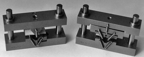
Fig. 2: Semi-articulated flexure fixtures: three-point loading (left) and four-point loading (right).
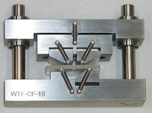
Fig. 1: A fully articulated, four-point loading flexure fixture.
Because of their brittle nature, ceramics, fiber-reinforced or unreinforced, are difficult to test in pure tension, compression and shear, primarily due to difficulties in gripping and uniformly loading the brittle specimen. In contrast, a flexural specimen simply rests on two supports and is loaded at one or two points along its length, making the test very easy to perform. This explains why those involved with ceramic-matrix composites and bulk ceramics use flexural testing of a beam more commonly than those working with less brittle materials.
There are other factors as well. The tensile strength of the material can be very sensitive to flaws and defects, including those induced during specimen fabrication, as well as stress concentrations induced by the gripping method. Thus, despite extremely careful preparation, there can be considerable scatter in test data. Compressive strength is difficult to obtain because the materials tend to be much stronger in compression than in shear. Even in a pure compression test, the shear stresses that occur at 45° to the direction of applied compressive load can cause a premature shear failure. Shear strength is the most difficult to determine. Ceramics are typically brittle materials, which by definition means that they are weaker in tension than in shear. Thus, even if a pure shear stress state is induced in the specimen, then at 45° to the direction of shear loading a tensile stress of magnitude equal to the applied shear stress is present. As a result, the material actually fails in tension.
Given these difficulties, a flexural (bending) test is often used. But it is desirable to induce a pure stress state in the test specimen over at least some representative volume of the material. In a flexural test, the stress state is neither pure (it varies from tension on one surface to compression on the other, with shear present as well), nor uniform (it varies along the length of the specimen). Consistent with the discussion in the previous paragraph, a brittle flexural specimen will usually fail at its tensile surface and, accordingly, the test measures tensile strength. As it is in the pure tension test, tensile strength in the flexural test is sensitive to defects in material and specimen preparation. But in this case, the sensitivity is confined primarily to the tensile surface in the region of highest stress. Because a relatively small volume of material is involved, it is at least possible to obtain test results with less data scatter.
The flexural loading configuration is defined by how many contact points there are between the specimen and the test fixture. Thus it is termed three-point loading if there are two supports and one loading point, and four-point loading if there are two loading points. While this is potentially confusing, it is standard terminology (see “Editor's Picks”).
ASTM C 1161 is the primary governing standard for flexural testing of ceramics.1 It defines three specimen sizes, termed Configurations A, B, and C, with specimens 1.5 mm, 3.0 mm and 6.0 mm (0.06 inches, 0.12 inches and 0.24 inches) thick, respectively, tested on corresponding support spans of 20 mm, 40 mm and 80 mm (0.79 inches, 1.57 inches and 3.15 inches). Note that each configuration defines a span length-to-thickness ratio of approximately 13:1 and thus all are geometrically similar. However, it has been estimated2 (and my own observations support this) that 90 percent or more of the flexural strength specimens prepared in the United States conform to Configuration B. It is certainly a convenient specimen size with which to work. Although the standard permits either three- or four-point loading and either a semi-articulated or a fully articulated test fixture, most testing is conducted using a fully articulated, four-point loading configuration. Such a fixture is shown in Fig. 1, with a specimen installed. Note that three of the specimen contact cylinders are free to pivot about axes parallel to the length of the specimen, while the lower left support is fixed, to prevent rigid body rotation. Also, the loading head is free to pivot about an axis perpendicular to the specimen axis to equally distribute the applied load between the two loading cylinders.
Use of a fully articulated fixture is particularly important when testing brittle materials: If the loading and support cylinders do not uniformly contact the specimen across its width, nonuniform flexural stresses will be induced, leading to premature failures. Also, ceramic-matrix composites are typically subjected to high-temperature processing, during which the initially flat specimen may twist, warp and otherwise deform. But it is often desirable to test the specimen in this as-fabricated (as-fired) condition to avoid grinding-induced surface flaws or to simulate the actual use conditions of the material. Any specimen twist makes it impossible to uniformly load the specimen using a nonarticulating fixture.
Note also in Fig. 1 that the contact cylinders are free to roll along the length of the specimen as the load is applied, as prescribed in ASTM C 1161. The lower cylinders roll outward as this (tensile) surface lengthens, while the upper cylinders roll inward as this (compressive) surface shortens. This prevents the development of sliding friction forces on the specimen surfaces. Of course, local contact stresses still occur under the contact cylinders. Thus, the standard prescribes the cylinder diameters, so that these contact stresses can be defined.
Fig. 2 shows semi-articulated fixtures for three-point and four-point loading. Note that in these cases, two contact points are not pivoted. Considering the relatively small gain in fixture simplicity and the definite disadvantage of not fully accommodating specimen imperfections, there is little reason to use a semi-articulated fixture, although ASTM C 1161 does permit it when specific flatness requirements are met.
There are other ASTM standards for the flexural testing of ceramics and ceramic composites. For example, ASTM C 13413 specifically addresses ceramic composites, allowing a range of specimen sizes and support span-to-specimen thickness ratios. ASTM C 12114 is an extension of ASTM C 1161 for testing at elevated temperatures, while ASTM C 14215 is an extension for fracture toughness testing. However, the basic testing principles, and the corresponding test fixtures, are similar for all of these standards.
References
1ASTM Standard C 1161-02c (2002), “Flexural Strength of Advanced Ceramics at Ambient Temperature,” American Society for Testing and Materials, W. Conshohocken, Pa. (first issued in 1990).
2“Standards Update: Flexural Strength Specimens Undergo a Major Overhaul,” The AMPTIAC Quarterly, Vol. 6, No. 2, 2002.
3ASTM Standard C 1341-00 (2000), “Flexural Properties of Continuous Fiber-Reinforced Advanced Ceramic Composites,” American Society for Testing and Materials, W. Conshohocken, Pa. (first issued in 1996).
4ASTM Standard C 1211-02 (2002), “Flexural Strength of Advanced Ceramics at Elevated Temperatures,” American Society for Testing and Materials, W. Conshohocken, Pa (first issued in 1990 as an update of MIL-STD 1942, dated 1983).
5ASTM Standard C 1421-01b (2001), “Determination of Fracture Toughness of Advanced Ceramics at Ambient Temperature,” American Society for Testing and Materials, W. Conshohocken, Pa.
Dr. Donald F. Adams is the president of Wyoming Test Fixtures Inc. (Salt Lake City, Utah), which he founded in 1988. He holds a BS and an MS in mechanical engineering and a Ph.D in theoretical and applied mechanics. Following a total of 12 years of service with Northrop Aircraft Corp., the Aeronutronic Div. of Ford Motor Co. and the RAND Corp., he joined the University of Wyoming, directing its Composite Materials Research Group for 27 years before retiring in 1999. Dr. Adams continues to write, teach and serve on the test methods committees of ASTM and Composite Materials Handbook 17.


.jpg;maxWidth=300;quality=90;format=webp)


Related Content

Composite test methods (and specifications) for fiber-reinforced concrete structures
While initially focused on transitioning existing standards published by the American Concrete Institute, the relatively new ASTM Subcommittee D30.10 is developing new standardized test methods and material specifications for FRP composites.
Read More
Composite prepreg tack testing
A recently standardized prepreg tack test method has been developed for use in material selection, quality control and adjusting cure process parameters for automated layup processes.
Read More
Improving analyses of composite pressure vessels
Accurate geometry modeling and equivalent material property approximations captured by WoundSim will play a role in improving COPV analyses.
Read More
Material equivalence testing in shared composites databases
In response to traditionally proprietary polymer matrix composites (PMC) qualifications, NCAMP continues its efforts to make material property databases publicly available.
Read MoreRead Next

Flexure test methods
The three fundamental mechanical property characterization tests of materials are tension, compression and shear. Note that flexure is not included. This article addresses some of the reasons why. When a beam resting on supports near its ends is loaded, the supported side is in tension and the opposite side is in
Read More
CW’s 2024 Top Shops survey offers new approach to benchmarking
Respondents that complete the survey by April 30, 2024, have the chance to be recognized as an honoree.
Read More
Composites end markets: Energy (2024)
Composites are used widely in oil/gas, wind and other renewable energy applications. Despite market challenges, growth potential and innovation for composites continue.
Read More